
Technical Product Specification
Page 7
... Description 1.1 Overview 11 1.1.1 Feature Summary 11 1.1.2 Board Layout (Top 13 1.1.3 Board Layout (Bottom 15 1.1.4 Block Diagram 17 1.2 Online Support 18 1.3 Processor 18 1.4 System Memory 19 1.4.1 Memory Configurations 20 1.5 Intel® QS77 Express Chipset 22 1.5.1 Direct Media Interface (DMI 22 1.5.2 Display Interfaces 22 1.6 Graphics Subsystem 22 1.6.1 Integrated Graphics 22 1.6.2 USB 24 1.7 SATA Interface 24...
... Description 1.1 Overview 11 1.1.1 Feature Summary 11 1.1.2 Board Layout (Top 13 1.1.3 Board Layout (Bottom 15 1.1.4 Block Diagram 17 1.2 Online Support 18 1.3 Processor 18 1.4 System Memory 19 1.4.1 Memory Configurations 20 1.5 Intel® QS77 Express Chipset 22 1.5.1 Direct Media Interface (DMI 22 1.5.2 Display Interfaces 22 1.6 Graphics Subsystem 22 1.6.1 Integrated Graphics 22 1.6.2 USB 24 1.7 SATA Interface 24...

Technical Product Specification
Page 8
Intel Desktop Board D33217CK Technical Product Specification 2 Technical Reference 2.1 Memory Resources 33 2.1.1 Addressable Memory 33 2.1.2 Memory Map 35 2.2 Connectors and Headers 35 2.2.1 Back Panel Connectors 36 2.2.2 Connectors and Headers (Bottom 37...Fan Header Current Capability 48 2.6 Thermal Considerations 48 2.7 Reliability 51 2.8 Environmental 51 3 Overview of BIOS Features 3.1 Introduction 53 3.2 BIOS Flash Memory Organization 54 3.3 System Management BIOS (SMBIOS 54 3.4 Legacy USB Support 54 3.5 BIOS Updates 55 3.5.1 Language Support 55 3.5.2 Custom Splash Screen 56...
Intel Desktop Board D33217CK Technical Product Specification 2 Technical Reference 2.1 Memory Resources 33 2.1.1 Addressable Memory 33 2.1.2 Memory Map 35 2.2 Connectors and Headers 35 2.2.1 Back Panel Connectors 36 2.2.2 Connectors and Headers (Bottom 37...Fan Header Current Capability 48 2.6 Thermal Considerations 48 2.7 Reliability 51 2.8 Environmental 51 3 Overview of BIOS Features 3.1 Introduction 53 3.2 BIOS Flash Memory Organization 54 3.3 System Management BIOS (SMBIOS 54 3.4 Legacy USB Support 54 3.5 BIOS Updates 55 3.5.1 Language Support 55 3.5.2 Custom Splash Screen 56...

Technical Product Specification
Page 9
... 9. Connection Diagram for Front Panel Header 42 11. Localized High Temperature Zones 49 ix Major Board Components (Bottom 15 3. Connectors and Headers (Bottom 37 10. Memory Channel and SO-DIMM Configuration 21 5. Detailed System...
... 9. Connection Diagram for Front Panel Header 42 11. Localized High Temperature Zones 49 ix Major Board Components (Bottom 15 3. Connectors and Headers (Bottom 37 10. Memory Channel and SO-DIMM Configuration 21 5. Detailed System...
Technical Product Specification
Page 10
... Current Capability 48 17. Tcontrol Values for Components 50 18. Master Key and User Hard Drive Password Functions 58 23. Supported Memory Configurations 19 5. System Memory Map 35 9. Dual-Port Front Panel USB 2.0 Header 40 12. 19 V Internal Power Supply Connector 41 13. Port 80h... for Components 50 19. Front-panel Power LED Blink Codes 61 25. Port 80h POST Codes 63 28. EMC Regulations 73 31. Intel Desktop Board D33217CK Technical Product Specification Tables 1. States for BIOS Recovery 56 21. Safety Standards 69 30. AcceptableDrives/Media Types for a ...
... Current Capability 48 17. Tcontrol Values for Components 50 18. Master Key and User Hard Drive Password Functions 58 23. Supported Memory Configurations 19 5. System Memory Map 35 9. Dual-Port Front Panel USB 2.0 Header 40 12. 19 V Internal Power Supply Connector 41 13. Port 80h... for Components 50 19. Front-panel Power LED Blink Codes 61 25. Port 80h POST Codes 63 28. EMC Regulations 73 31. Intel Desktop Board D33217CK Technical Product Specification Tables 1. States for BIOS Recovery 56 21. Safety Standards 69 30. AcceptableDrives/Media Types for a ...
Technical Product Specification
Page 11
... Card connector • One PCI Express Full-Mini Card connector • Intel® BIOS resident in the Serial Peripheral Interface (SPI) Flash device • Support for 1.35 V low voltage JEDEC memory Intel® QS77 Express Chipset consisting of the board. Table 2. Feature Summary ...Form Factor Processor Memory Chipset 4.0 inches by 4.0 inches (101.60 millimeters by 101.60 millimeters) • Soldered-down Intel® Core™ i3-3217U processor with ...
... Card connector • One PCI Express Full-Mini Card connector • Intel® BIOS resident in the Serial Peripheral Interface (SPI) Flash device • Support for 1.35 V low voltage JEDEC memory Intel® QS77 Express Chipset consisting of the board. Table 2. Feature Summary ...Form Factor Processor Memory Chipset 4.0 inches by 4.0 inches (101.60 millimeters by 101.60 millimeters) • Soldered-down Intel® Core™ i3-3217U processor with ...
Technical Product Specification
Page 18
... World Wide Web site: http://www.intel.com/products/motherboard/index.htm http://www.intel.com/p/en_US/support?iid=hdr+support http://ark.intel.com Chipset information BIOS and driver updates Tested memory Integration information http://www.intel.com/products/desktop/chipsets/index.htm http://downloadcenter.intel.com http://www.intel.com/support/motherboards/desktop/sb/CS025414...
... World Wide Web site: http://www.intel.com/products/motherboard/index.htm http://www.intel.com/p/en_US/support?iid=hdr+support http://ark.intel.com Chipset information BIOS and driver updates Tested memory Integration information http://www.intel.com/products/desktop/chipsets/index.htm http://downloadcenter.intel.com http://www.intel.com/support/motherboards/desktop/sb/CS025414...

Technical Product Specification
Page 19
...x 16 4 128 M x 16 4 2 GB 1 Gb 128 M x 8 16 F 4 GB 2 Gb 256 M x 8 16 8 GB 4 Gb 512 M x 8 16 Note: System memory configurations are subject to accurately configure memory settings for voltage detection • DDR3 1600 MHz, DDR3 1333 MHz, and DDR3 1066 MHz SDRAM SO-DIMMs NOTE To be fully... • Unbuffered, single-sided or double-sided SO-DIMMs • 16 GB maximum total system memory (with SO-DIMMs that support the Serial Presence Detect (SPD) data structure. Supported Memory Configurations Raw Card Version A SO-DIMM Capacity 1 GB 2 GB DRAM Device Technology 1 Gb 2...
...x 16 4 128 M x 16 4 2 GB 1 Gb 128 M x 8 16 F 4 GB 2 Gb 256 M x 8 16 8 GB 4 Gb 512 M x 8 16 Note: System memory configurations are subject to accurately configure memory settings for voltage detection • DDR3 1600 MHz, DDR3 1333 MHz, and DDR3 1066 MHz SDRAM SO-DIMMs NOTE To be fully... • Unbuffered, single-sided or double-sided SO-DIMMs • 16 GB maximum total system memory (with SO-DIMMs that support the Serial Presence Detect (SPD) data structure. Supported Memory Configurations Raw Card Version A SO-DIMM Capacity 1 GB 2 GB DRAM Device Technology 1 Gb 2...

Technical Product Specification
Page 20
... information about ... Tested Memory Refer to: http://support.intel.com/support/motherboards/desktop/sb /CS-025414.htm 1.4.1 Memory Configurations The processor supports the following types of both SO-DIMM channels are unequal. This mode is used between channels, the slowest memory timing will be equal....other . If different speed SO-DIMMs are used between channels, the slowest memory timing will be used . Technology and device width can vary from one channel to : http://www.intel.com/support/motherboards/desktop/sb/cs011965.htm 20 This mode offers the highest throughput...
... information about ... Tested Memory Refer to: http://support.intel.com/support/motherboards/desktop/sb /CS-025414.htm 1.4.1 Memory Configurations The processor supports the following types of both SO-DIMM channels are unequal. This mode is used between channels, the slowest memory timing will be equal....other . If different speed SO-DIMMs are used between channels, the slowest memory timing will be used . Technology and device width can vary from one channel to : http://www.intel.com/support/motherboards/desktop/sb/cs011965.htm 20 This mode offers the highest throughput...
Technical Product Specification
Page 21
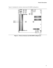
Product Description Figure 4 illustrates the memory channel and SO-DIMM configuration. Memory Channel and SO-DIMM Configuration 21 Figure 4.
Product Description Figure 4 illustrates the memory channel and SO-DIMM configuration. Memory Channel and SO-DIMM Configuration 21 Figure 4.
Technical Product Specification
Page 22
The processor houses the memory interface, display planes, and pipes while the PCH has transcoder and display interface or ports. The display data from the frame buffer is processed in ... for protecting high definition content against unauthorized copy or unreceptive between the processor and the PCH. The PCH receives the display data over Intel® Flexible Display Interface (Intel® FDI) and transcodes the data as per the display protocol and driven to the processor and the USB, SATA, LPC, LAN, and...
The processor houses the memory interface, display planes, and pipes while the PCH has transcoder and display interface or ports. The display data from the frame buffer is processed in ... for protecting high definition content against unauthorized copy or unreceptive between the processor and the PCH. The PCH receives the display data over Intel® Flexible Display Interface (Intel® FDI) and transcodes the data as per the display protocol and driven to the processor and the USB, SATA, LPC, LAN, and...
Technical Product Specification
Page 23
...-bit/96 kHz audio of lossless audio formats such as graphics memory to balance 2D/3D graphics and system performance. Product Description 1.6.1.1 Intel® High Definition (Intel® HD) Graphics The Intel HD graphics controller features the following audio technologies are supported by ... • LPCM, 192 kHz/24-bit, 8 Channel 23 The port is compatible with 4 GB and above system memory configuration 1.6.1.2 Video Memory Allocation Intel® Dynamic Video Memory Technology (DVMT) is allocated based on a single cable. If your computer is configured to use as Dolby* TrueHD ...
...-bit/96 kHz audio of lossless audio formats such as graphics memory to balance 2D/3D graphics and system performance. Product Description 1.6.1.1 Intel® High Definition (Intel® HD) Graphics The Intel HD graphics controller features the following audio technologies are supported by ... • LPCM, 192 kHz/24-bit, 8 Channel 23 The port is compatible with 4 GB and above system memory configuration 1.6.1.2 Video Memory Allocation Intel® Dynamic Video Memory Technology (DVMT) is allocated based on a single cable. If your computer is configured to use as Dolby* TrueHD ...
Technical Product Specification
Page 25
... required. 1.10 Hardware Management Subsystem The hardware management features enable the board to support communications over a single cable. Figure 1 on Intel Desktop Board D33217CK as a plug and play interface. Product Description 1.8 Real-Time Clock Subsystem A coin-cell battery (CR2032) powers the... real-time clock and CMOS memory. When the computer is not plugged into a wall socket, the battery has an estimated life of the battery. 1.9 Connectivity 1.9.1 Thunderbolt...
... required. 1.10 Hardware Management Subsystem The hardware management features enable the board to support communications over a single cable. Figure 1 on Intel Desktop Board D33217CK as a plug and play interface. Product Description 1.8 Real-Time Clock Subsystem A coin-cell battery (CR2032) powers the... real-time clock and CMOS memory. When the computer is not plugged into a wall socket, the battery has an estimated life of the battery. 1.9 Connectivity 1.9.1 Thunderbolt...

Technical Product Specification
Page 26
... Fan Header 26 Intel Desktop Board D33217CK Technical Product Specification 1.10.1 Hardware Monitoring The hardware monitoring and fan control subsystem is based on a Nuvoton NPCE791C embedded controller, which supports the following: • Processor and system ambient temperature monitoring • Chassis fan speed monitoring • Voltage monitoring of +12 V, +5 V, +3.3 V, Memory Vcc (V_SM), +Vccp...
... Fan Header 26 Intel Desktop Board D33217CK Technical Product Specification 1.10.1 Hardware Monitoring The hardware monitoring and fan control subsystem is based on a Nuvoton NPCE791C embedded controller, which supports the following: • Processor and system ambient temperature monitoring • Chassis fan speed monitoring • Voltage monitoring of +12 V, +5 V, +3.3 V, Memory Vcc (V_SM), +Vccp...

Technical Product Specification
Page 33
... (256 MB) The board provides the capability to an equivalent sized logical address range located just above the top of DRAM (total system memory). These functions include the following: • BIOS/SPI Flash device (16 Mbit) • Local APIC (19 MB) • Direct...system critical functions. Figure 7 shows a schematic of addressable system memory. 2 Technical Reference 2.1 Memory Resources 2.1.1 Addressable Memory The board utilizes 16 GB of the system memory map. On a system that is no overlap of system memory installed, it is dynamically allocated for PCI Express add-in cards...
... (256 MB) The board provides the capability to an equivalent sized logical address range located just above the top of DRAM (total system memory). These functions include the following: • BIOS/SPI Flash device (16 Mbit) • Local APIC (19 MB) • Direct...system critical functions. Figure 7 shows a schematic of addressable system memory. 2 Technical Reference 2.1 Memory Resources 2.1.1 Addressable Memory The board utilizes 16 GB of the system memory map. On a system that is no overlap of system memory installed, it is dynamically allocated for PCI Express add-in cards...

Technical Product Specification
Page 35
...64 KB 64 KB 96 KB 160 KB 1 KB 127 KB 512 KB Description Extended memory Runtime BIOS Reserved Potential available high DOS memory (open to the board. Video memory and BIOS Extended BIOS data (movable by the external devices could cause damage to the ...external to devices inside the computer's chassis, such as fans and internal peripherals. A fault in the load presented by memory manager software) Extended conventional memory Conventional memory 2.2 Connectors and Headers CAUTION Only the following connectors and headers have overcurrent protection: back panel and front panel USB. ...
...64 KB 64 KB 96 KB 160 KB 1 KB 127 KB 512 KB Description Extended memory Runtime BIOS Reserved Potential available high DOS memory (open to the board. Video memory and BIOS Extended BIOS data (movable by the external devices could cause damage to the ...external to devices inside the computer's chassis, such as fans and internal peripherals. A fault in the load presented by memory manager software) Extended conventional memory Conventional memory 2.2 Connectors and Headers CAUTION Only the following connectors and headers have overcurrent protection: back panel and front panel USB. ...

Technical Product Specification
Page 53
The BIOS displays a message during POST identifying the type of BIOS Features 3.1 Introduction The board uses a Intel Visual BIOS that is stored in the Serial Peripheral Interface Flash Memory (SPI Flash) and can be updated using a disk-based program. Section 2.3 on page 44 shows how to put the board in.... NOTE The maintenance menu is displayed only when the board is accessed by pressing the key after the Power-On Self-Test (POST) memory test begins and before the operating system boot begins. The SPI Flash contains the Visual BIOS Setup program, POST, the PCI auto-configuration utility...
The BIOS displays a message during POST identifying the type of BIOS Features 3.1 Introduction The board uses a Intel Visual BIOS that is stored in the Serial Peripheral Interface Flash Memory (SPI Flash) and can be updated using a disk-based program. Section 2.3 on page 44 shows how to put the board in.... NOTE The maintenance menu is displayed only when the board is accessed by pressing the key after the Power-On Self-Test (POST) memory test begins and before the operating system boot begins. The SPI Flash contains the Visual BIOS Setup program, POST, the PCI auto-configuration utility...
Technical Product Specification
Page 54
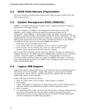
...information about the computing system and its components. POST begins. 3. Intel Desktop Board D33217CK Technical Product Specification 3.2 BIOS Flash Memory Organization The Serial Peripheral Interface Flash Memory (SPI Flash) includes a 64 Mb (8192 KB) flash memory device. 3.3 System Management BIOS (SMBIOS) SMBIOS is set to ... revision level • Fixed-system data, such as peripherals, serial numbers, and asset tags • Resource data, such as memory size, cache size, and processor speed • Dynamic data, such as event detection and error logging Non-Plug and Play operating...
...information about the computing system and its components. POST begins. 3. Intel Desktop Board D33217CK Technical Product Specification 3.2 BIOS Flash Memory Organization The Serial Peripheral Interface Flash Memory (SPI Flash) includes a 64 Mb (8192 KB) flash memory device. 3.3 System Management BIOS (SMBIOS) SMBIOS is set to ... revision level • Fixed-system data, such as peripherals, serial numbers, and asset tags • Resource data, such as memory size, cache size, and processor speed • Dynamic data, such as event detection and error logging Non-Plug and Play operating...
Technical Product Specification
Page 55
... to select where the BIOS .bio file is located and perform the update from the file location on the Web. • Intel® Flash Memory Update Utility, which enables automated updating while in the Windows environment. Error Messages and Beep Codes 6. Using this utility, the BIOS... can be updated from a file on the Intel World Wide Web site: • Intel® Express BIOS Update utility, which requires booting from the ...
... to select where the BIOS .bio file is located and perform the update from the file location on the Web. • Intel® Flash Memory Update Utility, which enables automated updating while in the Windows environment. Error Messages and Beep Codes 6. Using this utility, the BIOS... can be updated from a file on the Intel World Wide Web site: • Intel® Express BIOS Update utility, which requires booting from the ...

Technical Product Specification
Page 61
... repeats (blinks and pause) until the BIOS update is powered off . Note: Disabled per default BIOS setup option. Memory error On-off (1.0 second each . Memory Size Decreased Memory size has decreased since the last boot. The CMOS checksum is found. 4.2 BIOS Error Messages Table 26 lists the... error messages and provides a brief description of 16 blinks. Note When no memory was removed, then memory may have been corrupted. CMOS memory may be bad. This will be losing power. Thermal trip warning Each beep will result in progress Video error...
... repeats (blinks and pause) until the BIOS update is powered off . Note: Disabled per default BIOS setup option. Memory error On-off (1.0 second each . Memory Size Decreased Memory size has decreased since the last boot. The CMOS checksum is found. 4.2 BIOS Error Messages Table 26 lists the... error messages and provides a brief description of 16 blinks. Note When no memory was removed, then memory may have been corrupted. CMOS memory may be bad. This will be losing power. Thermal trip warning Each beep will result in progress Video error...
Technical Product Specification
Page 62
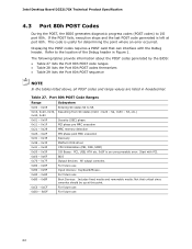
... point. 0xC0 - 0xCF For future use 0xD0 - 0xDF For future use 0xB0 - 0xBF Boot Devices: Includes fixed media and removable media. Intel Desktop Board D33217CK Technical Product Specification 4.3 Port 80h POST Codes During the POST, the BIOS generates diagnostic progress codes (POST codes) to I ... in Figure 1. S3, etc.) 0x40, 0x50 0x01 - 0x0F Security (SEC) phase 0x11 - 0x1F PEI phase pre MRC execution 0x21 - 0x29 MRC memory detection 0x2A - 0x2F PEI phase post MRC execution 0x31 - 0x35 Recovery 0x36 - 0x3F Platform DXE driver 0x41 - 0x4F CPU Initialization (PEI, DXE, ...
... point. 0xC0 - 0xCF For future use 0xD0 - 0xDF For future use 0xB0 - 0xBF Boot Devices: Includes fixed media and removable media. Intel Desktop Board D33217CK Technical Product Specification 4.3 Port 80h POST Codes During the POST, the BIOS generates diagnostic progress codes (POST codes) to I ... in Figure 1. S3, etc.) 0x40, 0x50 0x01 - 0x0F Security (SEC) phase 0x11 - 0x1F PEI phase pre MRC execution 0x21 - 0x29 MRC memory detection 0x2A - 0x2F PEI phase post MRC execution 0x31 - 0x35 Recovery 0x36 - 0x3F Platform DXE driver 0x41 - 0x4F CPU Initialization (PEI, DXE, ...


