
Technical Product Specification
Page 2
... evaluated as medical, industrial, alarm systems, test equipment, etc. Intel and Intel Core are trademarks of Computing Board with BIOS identifier GKPPT10H.86A. All rights reserved. EXCEPT AS PROVIDED IN INTEL'S TERMS AND CONDITIONS OF SALE FOR SUCH PRODUCTS, INTEL ASSUMES NO LIABILITY WHATSOEVER, AND INTEL DISCLAIMS ANY EXPRESS OR IMPLIED WARRANTY, RELATING TO SALE AND...
... evaluated as medical, industrial, alarm systems, test equipment, etc. Intel and Intel Core are trademarks of Computing Board with BIOS identifier GKPPT10H.86A. All rights reserved. EXCEPT AS PROVIDED IN INTEL'S TERMS AND CONDITIONS OF SALE FOR SUCH PRODUCTS, INTEL ASSUMES NO LIABILITY WHATSOEVER, AND INTEL DISCLAIMS ANY EXPRESS OR IMPLIED WARRANTY, RELATING TO SALE AND...
Technical Product Specification
Page 3
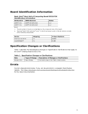
...Information AA Revision BIOS Revision Notes G69977-201 GKPPT10H.86A.0020 1,2 G69977-301 GKPPT10H.86A.0025 1,2 Notes: 1. See http://developer.intel.com/products/desktop/motherboard/index.htm for the latest documentation. iii The Intel® QS77 PCH and Intel® Core&#...Specification Changes or Clarifications Table 1 indicates the Specification Changes or Specification Clarifications that apply to the Intel® Desktop Board D33217CK. Board Identification Information Basic Intel® Next Unit of Changes or Clarifications October 2012 Spec Change Corrected a typo in a...
...Information AA Revision BIOS Revision Notes G69977-201 GKPPT10H.86A.0020 1,2 G69977-301 GKPPT10H.86A.0025 1,2 Notes: 1. See http://developer.intel.com/products/desktop/motherboard/index.htm for the latest documentation. iii The Intel® QS77 PCH and Intel® Core&#...Specification Changes or Clarifications Table 1 indicates the Specification Changes or Specification Clarifications that apply to the Intel® Desktop Board D33217CK. Board Identification Information Basic Intel® Next Unit of Changes or Clarifications October 2012 Spec Change Corrected a typo in a...
Technical Product Specification
Page 5
... is intended to provide detailed, technical information about the conventions used on Intel Next Unit of Computing Board D33217CK A map of the resources of the Intel Next Unit of Computing Board The features supported by the BIOS Setup program A description of the BIOS error messages, beep codes, and POST codes Regulatory compliance and battery...
... is intended to provide detailed, technical information about the conventions used on Intel Next Unit of Computing Board D33217CK A map of the resources of the Intel Next Unit of Computing Board The features supported by the BIOS Setup program A description of the BIOS error messages, beep codes, and POST codes Regulatory compliance and battery...

Technical Product Specification
Page 8
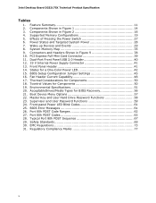
Intel Desktop Board D33217CK Technical Product Specification 2 Technical Reference 2.1 Memory Resources 33 2.1.1 Addressable Memory 33 2.1.2 Memory Map 35 2.2 Connectors and Headers 35 2.2.1 Back Panel Connectors 36 2.2.2 Connectors and Headers (Bottom 37 2.3 BIOS Setup Configuration Jumper 44 2.4 Mechanical Considerations 46 2.4.1 Form Factor 46 2.5 Electrical Considerations 47 2.5.1 Power Supply Considerations 47 2.5.2 Fan Header Current Capability...
Intel Desktop Board D33217CK Technical Product Specification 2 Technical Reference 2.1 Memory Resources 33 2.1.1 Addressable Memory 33 2.1.2 Memory Map 35 2.2 Connectors and Headers 35 2.2.1 Back Panel Connectors 36 2.2.2 Connectors and Headers (Bottom 37 2.3 BIOS Setup Configuration Jumper 44 2.4 Mechanical Considerations 46 2.4.1 Form Factor 46 2.5 Electrical Considerations 47 2.5.1 Power Supply Considerations 47 2.5.2 Fan Header Current Capability...

Technical Product Specification
Page 9
... Address Map 34 8. Major Board Components (Top 13 2. Thermal Solution and Fan Header 26 6. Connection Diagram for Front Panel Header 42 11. Location of the BIOS Configuration Setup Jumper 44 13. Major Board Components (Bottom 15 3. Board Dimensions 46 14. Contents Figures 1. Back Panel Connectors 36 9. Connectors and Headers (Bottom 37...
... Address Map 34 8. Major Board Components (Top 13 2. Thermal Solution and Fan Header 26 6. Connection Diagram for Front Panel Header 42 11. Location of the BIOS Configuration Setup Jumper 44 13. Major Board Components (Bottom 15 3. Board Dimensions 46 14. Contents Figures 1. Back Panel Connectors 36 9. Connectors and Headers (Bottom 37...
Technical Product Specification
Page 10
... 28 7. Connectors and Headers Shown in Figure 2 16 4. Boot Device Menu Options 57 22. Front-panel Power LED Blink Codes 61 25. BIOS Error Messages 61 26. Front Panel Header 41 14. EMC Regulations 73 31. Components Shown in Figure 1 14 3. Master Key and User Hard... Drive Password Functions 58 23. BIOS Setup Configuration Jumper Settings 45 16. Environmental Specifications 51 20. Dual-Port Front Panel USB 2.0 Header 40 12. 19 V Internal Power Supply Connector ...
... 28 7. Connectors and Headers Shown in Figure 2 16 4. Boot Device Menu Options 57 22. Front-panel Power LED Blink Codes 61 25. BIOS Error Messages 61 26. Front Panel Header 41 14. EMC Regulations 73 31. Components Shown in Figure 1 14 3. Master Key and User Hard... Drive Password Functions 58 23. BIOS Setup Configuration Jumper Settings 45 16. Environmental Specifications 51 20. Dual-Port Front Panel USB 2.0 Header 40 12. 19 V Internal Power Supply Connector ...
Technical Product Specification
Page 11
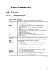
... Hub (PCH) Connectivity Graphics Audio Peripheral Interfaces Expansion Capabilities BIOS Thunderbolt™ Technology Interface • Integrated graphics support for processors with Intel® Graphics Technology: ― One High Definition Multimedia Interface* (HDMI*) back panel connector Intel® High Definition Audio via the HDMI v1.4a interface... • One PCI Express Half-Mini Card connector • One PCI Express Full-Mini Card connector • Intel® BIOS resident in the Serial Peripheral Interface (SPI) Flash device • Support for 1.35 V low voltage JEDEC memory...
... Hub (PCH) Connectivity Graphics Audio Peripheral Interfaces Expansion Capabilities BIOS Thunderbolt™ Technology Interface • Integrated graphics support for processors with Intel® Graphics Technology: ― One High Definition Multimedia Interface* (HDMI*) back panel connector Intel® High Definition Audio via the HDMI v1.4a interface... • One PCI Express Half-Mini Card connector • One PCI Express Full-Mini Card connector • Intel® BIOS resident in the Serial Peripheral Interface (SPI) Flash device • Support for 1.35 V low voltage JEDEC memory...
Technical Product Specification
Page 18
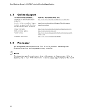
... World Wide Web site: http://www.intel.com/products/motherboard/index.htm http://www.intel.com/p/en_US/support?iid=hdr+support http://ark.intel.com Chipset information BIOS and driver updates Tested memory Integration information http://www.intel.com/products/desktop/chipsets/index.htm http://downloadcenter.intel.com http://www.intel.com/support/motherboards/desktop/sb/CS025414...
... World Wide Web site: http://www.intel.com/products/motherboard/index.htm http://www.intel.com/p/en_US/support?iid=hdr+support http://ark.intel.com Chipset information BIOS and driver updates Tested memory Integration information http://www.intel.com/products/desktop/chipsets/index.htm http://downloadcenter.intel.com http://www.intel.com/support/motherboards/desktop/sb/CS025414...

Technical Product Specification
Page 19
If non-SPD memory is installed, the BIOS will attempt to correctly configure the memory settings, but performance and reliability may not function under the determined frequency. Product Description 1.4 System Memory The board ...-DIMM sockets and supports the following memory features: • 1.5 V DDR3 SDRAM SO-DIMMs with gold plated contacts • Support for optimum performance. This allows the BIOS to read the SPD data and program the chipset to change. 19 Refer to Section 2.1.1 on page 33 for information on availability and are based...
If non-SPD memory is installed, the BIOS will attempt to correctly configure the memory settings, but performance and reliability may not function under the determined frequency. Product Description 1.4 System Memory The board ...-DIMM sockets and supports the following memory features: • 1.5 V DDR3 SDRAM SO-DIMMs with gold plated contacts • Support for optimum performance. This allows the BIOS to read the SPD data and program the chipset to change. 19 Refer to Section 2.1.1 on page 33 for information on availability and are based...
Technical Product Specification
Page 24
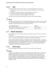
...latest available by Intel. 24 For information about installing drivers during installation. The underlying SATA functionality is attached to use AHCI mode, AHCI must be enabled in both legacy and native modes. The SATA controller can operate in the BIOS. NOTE In ...SATA Interface The board provides one front panel connector) • Two ports are implemented with a theoretical maximum transfer rate of 6 Gb/s. Intel Desktop Board D33217CK Technical Product Specification 1.6.2 USB The board supports seven USB 2.0 ports. A point-to install the AHCI drivers. The port...
...latest available by Intel. 24 For information about installing drivers during installation. The underlying SATA functionality is attached to use AHCI mode, AHCI must be enabled in both legacy and native modes. The SATA controller can operate in the BIOS. NOTE In ...SATA Interface The board provides one front panel connector) • Two ports are implemented with a theoretical maximum transfer rate of 6 Gb/s. Intel Desktop Board D33217CK Technical Product Specification 1.6.2 USB The board supports seven USB 2.0 ports. A point-to install the AHCI drivers. The port...
Technical Product Specification
Page 25
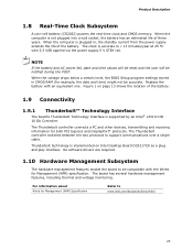
When the voltage drops below a certain level, the BIOS Setup program settings stored in , the standby current from the power supply extends the life of the battery. The Thunderbolt controller switches between the two protocols to www.intel.com/design/archives/wfm/ 25 The board has several ... RAM (for Management (WfM) Specification Refer to support communications over a single cable. Figure 1 on Intel Desktop Board D33217CK as a plug and play interface. The clock is supported by an Intel® L3310 CIO 10 Gb Controller. When the computer is not plugged into a wall socket, the...
When the voltage drops below a certain level, the BIOS Setup program settings stored in , the standby current from the power supply extends the life of the battery. The Thunderbolt controller switches between the two protocols to www.intel.com/design/archives/wfm/ 25 The board has several ... RAM (for Management (WfM) Specification Refer to support communications over a single cable. Figure 1 on Intel Desktop Board D33217CK as a plug and play interface. The clock is supported by an Intel® L3310 CIO 10 Gb Controller. When the computer is not plugged into a wall socket, the...
Technical Product Specification
Page 30
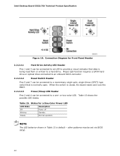
... page 41 1.11.2.2 Instantly Available PC Technology Instantly Available PC technology enables the board to be set using the Last Power State feature in the BIOS, the computer will appear to enter the ACPI S3 (Suspend-toRAM) sleep-state. Table 8 on page 29 lists the devices and events that ... the power state it was in before power was interrupted (on or off , and the front panel LED is set in the BIOS Setup program's Boot menu. Intel Desktop Board D33217CK Technical Product Specification 1.11.2.1 Power Input When resuming from an AC power failure, the computer returns to its last...
... page 41 1.11.2.2 Instantly Available PC Technology Instantly Available PC technology enables the board to be set using the Last Power State feature in the BIOS, the computer will appear to enter the ACPI S3 (Suspend-toRAM) sleep-state. Table 8 on page 29 lists the devices and events that ... the power state it was in before power was interrupted (on or off , and the front panel LED is set in the BIOS Setup program's Boot menu. Intel Desktop Board D33217CK Technical Product Specification 1.11.2.1 Power Input When resuming from an AC power failure, the computer returns to its last...

Technical Product Specification
Page 33
...memory). 2 Technical Reference 2.1 Memory Resources 2.1.1 Addressable Memory The board utilizes 16 GB of the system memory map. These functions include the following: • BIOS/SPI Flash device (16 Mbit) • Local APIC (19 MB) • Direct Media Interface (40 MB) • PCI Express configuration space (256... overlap of the installed memory due to system address space being allocated for PCI Express add-in cards, PCI Express configuration space, BIOS (SPI Flash device), and chipset overhead resides above the 4 GB boundary. All installed system memory can be used when there is...
...memory). 2 Technical Reference 2.1 Memory Resources 2.1.1 Addressable Memory The board utilizes 16 GB of the system memory map. These functions include the following: • BIOS/SPI Flash device (16 Mbit) • Local APIC (19 MB) • Direct Media Interface (40 MB) • PCI Express configuration space (256... overlap of the installed memory due to system address space being allocated for PCI Express add-in cards, PCI Express configuration space, BIOS (SPI Flash device), and chipset overhead resides above the 4 GB boundary. All installed system memory can be used when there is...

Technical Product Specification
Page 35
...9FBFF 00000 - 7FFFF Size 16382 MB 64 KB 64 KB 96 KB 160 KB 1 KB 127 KB 512 KB Description Extended memory Runtime BIOS Reserved Potential available high DOS memory (open to the board. Furthermore, improper connection of USB header single wire connectors may eventually overload the ...overcurrent protection and cause damage to the PCI Conventional bus). Video memory and BIOS Extended BIOS data (movable by the external devices could cause damage to devices inside the computer's chassis, such as fans and internal peripherals....
...9FBFF 00000 - 7FFFF Size 16382 MB 64 KB 64 KB 96 KB 160 KB 1 KB 127 KB 512 KB Description Extended memory Runtime BIOS Reserved Potential available high DOS memory (open to the board. Furthermore, improper connection of USB header single wire connectors may eventually overload the ...overcurrent protection and cause damage to the PCI Conventional bus). Video memory and BIOS Extended BIOS data (movable by the external devices could cause damage to devices inside the computer's chassis, such as fans and internal peripherals....
Technical Product Specification
Page 42
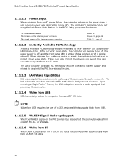
... hard drive or optical drive connected to an onboard SATA connector. 2.2.2.4.2 Reset Switch Header Pins 5 and 7 can be set via BIOS setup. 42 other patterns may be connected to a hard drive. Intel Desktop Board D33217CK Technical Product Specification Figure 10. Connection Diagram for a One-Color Power LED LED State Description Off Power...
... hard drive or optical drive connected to an onboard SATA connector. 2.2.2.4.2 Reset Switch Header Pins 5 and 7 can be set via BIOS setup. 42 other patterns may be connected to a hard drive. Intel Desktop Board D33217CK Technical Product Specification Figure 10. Connection Diagram for a One-Color Power LED LED State Description Off Power...

Technical Product Specification
Page 44
Location of the BIOS Setup Configuration jumper. Intel Desktop Board D33217CK Technical Product Specification 2.3 BIOS Setup Configuration Jumper CAUTION Do not move a jumper with the power on. Figure 12 shows the location of the BIOS Configuration Setup Jumper 44 Always turn off the power and unplug the power ...cord from the computer before changing a jumper setting. Otherwise, the board could be damaged. Table 16 describes the BIOS Setup configuration jumper settings for the three modes: normal, configure, and recovery. When the jumper is set to configure mode and ...
Location of the BIOS Setup Configuration jumper. Intel Desktop Board D33217CK Technical Product Specification 2.3 BIOS Setup Configuration Jumper CAUTION Do not move a jumper with the power on. Figure 12 shows the location of the BIOS Configuration Setup Jumper 44 Always turn off the power and unplug the power ...cord from the computer before changing a jumper setting. Otherwise, the board could be damaged. Table 16 describes the BIOS Setup configuration jumper settings for the three modes: normal, configure, and recovery. When the jumper is set to configure mode and ...

Technical Product Specification
Page 45
...configuration information and passwords for the jumper. Note that this Configure mode is displayed. The maintenance menu is the only way to clear the BIOS/CMOS settings. A recovery CD or flash drive is required. 45 Technical Reference Table 16 lists the settings for booting. After the POST ...runs, Setup runs automatically. Table 16. Recovery None The BIOS attempts to their default values. Press F9 (restore defaults) while in Configure mode to restore the BIOS/CMOS settings to recover the...
...configuration information and passwords for the jumper. Note that this Configure mode is displayed. The maintenance menu is the only way to clear the BIOS/CMOS settings. A recovery CD or flash drive is required. 45 Technical Reference Table 16 lists the settings for booting. After the POST ...runs, Setup runs automatically. Table 16. Recovery None The BIOS attempts to their default values. Press F9 (restore defaults) while in Configure mode to restore the BIOS/CMOS settings to recover the...

Technical Product Specification
Page 50
...the components and does not directly correspond to Section 1.2, page 18 http://www.intel.com/Products/Desktop/ Chipsets/ec-QS77/QS77technicaldocuments.htm 50 Maximum case temperatures are...Intel QS77 Express Chipset For processor case temperature, see processor datasheets and processor specification updates Intel QS77 Express Chipset 104 oC For information about Processor datasheets and specification updates Intel..., or operating frequency could affect case temperatures. Table 19. Intel Desktop Board D33217CK Technical Product Specification Table 18 provides maximum case temperatures for the...
...the components and does not directly correspond to Section 1.2, page 18 http://www.intel.com/Products/Desktop/ Chipsets/ec-QS77/QS77technicaldocuments.htm 50 Maximum case temperatures are...Intel QS77 Express Chipset For processor case temperature, see processor datasheets and processor specification updates Intel QS77 Express Chipset 104 oC For information about Processor datasheets and specification updates Intel..., or operating frequency could affect case temperatures. Table 19. Intel Desktop Board D33217CK Technical Product Specification Table 18 provides maximum case temperatures for the...

Technical Product Specification
Page 53
...Serial Peripheral Interface Flash Memory (SPI Flash) and can be updated using a disk-based program. 3 Overview of BIOS and a revision code. The SPI Flash contains the Visual BIOS Setup program, POST, the PCI auto-configuration utility, LAN EEPROM information, and Plug and Play support. The ... 2.3 on page 44 shows how to view and change the BIOS settings for the computer. The BIOS displays a message during POST identifying the type of BIOS Features 3.1 Introduction The board uses a Intel Visual BIOS that is powered-up, the BIOS compares the CPU version and the microcode version in the...
...Serial Peripheral Interface Flash Memory (SPI Flash) and can be updated using a disk-based program. 3 Overview of BIOS and a revision code. The SPI Flash contains the Visual BIOS Setup program, POST, the PCI auto-configuration utility, LAN EEPROM information, and Plug and Play support. The ... 2.3 on page 44 shows how to view and change the BIOS settings for the computer. The BIOS displays a message during POST identifying the type of BIOS Features 3.1 Introduction The board uses a Intel Visual BIOS that is powered-up, the BIOS compares the CPU version and the microcode version in the...
Technical Product Specification
Page 54
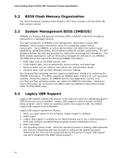
... default, Legacy USB support is set to Enabled. Legacy USB support is enabled by the BIOS allowing you apply power to enter and configure the BIOS Setup program and the maintenance menu. 4. Intel Desktop Board D33217CK Technical Product Specification 3.2 BIOS Flash Memory Organization The Serial Peripheral Interface Flash Memory (SPI Flash) includes a 64 Mb...
... default, Legacy USB support is set to Enabled. Legacy USB support is enabled by the BIOS allowing you apply power to enter and configure the BIOS Setup program and the maintenance menu. 4. Intel Desktop Board D33217CK Technical Product Specification 3.2 BIOS Flash Memory Organization The Serial Peripheral Interface Flash Memory (SPI Flash) includes a 64 Mb...


