
Product Specification
Page 15
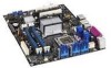
...Secondary PCI Express x16 (electrical x8) bus add-in card connector Front panel audio header Intel® 82801G I/O Controller Hub (ICH7-R or ICH7-DH) Primary PCI Express x16 (...optional) Processor core power connector Memory Controller Hub (MCH) fan header (optional) LGA775 processor socket Intel 82975X MCH DIMM Channel A sockets [2] Processor fan header DIMM Channel B sockets [2] Main power...ATA connectors (ICH7-R/ICH7-DH RAID) [4] Front chassis fan header Auxiliary front panel power LED header Front panel USB headers [2] IEEE-1394a front panel header Serial ATA RAID connectors (Discrete...
...Secondary PCI Express x16 (electrical x8) bus add-in card connector Front panel audio header Intel® 82801G I/O Controller Hub (ICH7-R or ICH7-DH) Primary PCI Express x16 (...optional) Processor core power connector Memory Controller Hub (MCH) fan header (optional) LGA775 processor socket Intel 82975X MCH DIMM Channel A sockets [2] Processor fan header DIMM Channel B sockets [2] Main power...ATA connectors (ICH7-R/ICH7-DH RAID) [4] Front chassis fan header Auxiliary front panel power LED header Front panel USB headers [2] IEEE-1394a front panel header Serial ATA RAID connectors (Discrete...

Product Specification
Page 47
Location of the LEDs. Item A B Description CPU LED VR LED LED Color Red Red Figure 16. Product Description 1.15 Onboard LEDs In addition to the standby power indicator, the board contains two LEDs that indicate the following: • The CPU LED indicates an elevated temperature on the processor that could effect performance • The VR LED indicates an elevated temperature in the processor voltage regulator circuit that could effect performance Figure 16 shows the locations of the CPU and Processor Voltage Regulator LEDs 47
Location of the LEDs. Item A B Description CPU LED VR LED LED Color Red Red Figure 16. Product Description 1.15 Onboard LEDs In addition to the standby power indicator, the board contains two LEDs that indicate the following: • The CPU LED indicates an elevated temperature on the processor that could effect performance • The VR LED indicates an elevated temperature in the processor voltage regulator circuit that could effect performance Figure 16 shows the locations of the CPU and Processor Voltage Regulator LEDs 47

Product Specification
Page 66
... panel yellow LED On/Off Switch [Red] FPBUT_IN In Power switch Ground Ground Not Connected N/C Not connected Dualcolored Power LED - + N/C Power Switch Singlecolored Power LED + - 9 87 65 43 21 +5 V DC Reset Switch - Figure 21 is a connection diagram for Front Panel Header 66 Table 29 lists the signal names of the front panel header. Intel Desktop Board D975XBX2 Technical...
... panel yellow LED On/Off Switch [Red] FPBUT_IN In Power switch Ground Ground Not Connected N/C Not connected Dualcolored Power LED - + N/C Power Switch Singlecolored Power LED + - 9 87 65 43 21 +5 V DC Reset Switch - Figure 21 is a connection diagram for Front Panel Header 66 Table 29 lists the signal names of the front panel header. Intel Desktop Board D975XBX2 Technical...

Product Specification
Page 67
... to internal debounce circuitry on the board.) At least two seconds must pull the SW_ON# pin to ground for a two-color LED. Technical Reference 2.7.2.4.1 Hard Drive Activity LED Header [Orange] Pins 1 and 3 [Orange] can be connected to an LED to provide a visual indicator that ...is normally open. or customer-specific. 2.7.2.4.4 Power Switch Header [Red] Pins 6 and 8 [Red] can be connected to a...
... to internal debounce circuitry on the board.) At least two seconds must pull the SW_ON# pin to ground for a two-color LED. Technical Reference 2.7.2.4.1 Hard Drive Activity LED Header [Orange] Pins 1 and 3 [Orange] can be connected to an LED to provide a visual indicator that ...is normally open. or customer-specific. 2.7.2.4.4 Power Switch Header [Red] Pins 6 and 8 [Red] can be connected to a...


