Product Guide
Page 5
... Systems 10 Desktop Board Components 11 Processor ...13 Power Requirements for Intel® Pentium® Processor Extreme Edition 13 Processor Type ...13 Main Memory ...14 Intel® 955X Express Chipset 14 Audio Subsystem ...15 Input/Output (I/O) Controller 16 LAN Subsystem ...16 LAN Subsystem Software 16 RJ-45 LAN Connector LEDs 16 Hi-Speed USB 2.0 Support...
... Systems 10 Desktop Board Components 11 Processor ...13 Power Requirements for Intel® Pentium® Processor Extreme Edition 13 Processor Type ...13 Main Memory ...14 Intel® 955X Express Chipset 14 Audio Subsystem ...15 Input/Output (I/O) Controller 16 LAN Subsystem ...16 LAN Subsystem Software 16 RJ-45 LAN Connector LEDs 16 Hi-Speed USB 2.0 Support...
Product Guide
Page 6
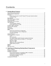
Intel Desktop Board D955XCS Product Guide Installing and Removing the Desktop Board 27 Installing and Removing a Processor 28 Installing a Processor 28 Installing the Processor Fan Heat Sink 31 Connecting the Processor Fan Heat Sink Cable 31 Removing ... Panel Audio Header 42 IEEE 1394a/b Headers 42 USB 2.0 Headers ...43 Front Panel Header...43 Alternate Power LED Header 43 Installing the Rear Panel Hi-Speed USB 2.0 Adapter 44 Installing the Front Panel USB/IEEE 1394/Audio Solution 45 Connecting Fans ...46 Connecting Fans and Chassis Intrusion 46 Connecting the Auxiliary...
Intel Desktop Board D955XCS Product Guide Installing and Removing the Desktop Board 27 Installing and Removing a Processor 28 Installing a Processor 28 Installing the Processor Fan Heat Sink 31 Connecting the Processor Fan Heat Sink Cable 31 Removing ... Panel Audio Header 42 IEEE 1394a/b Headers 42 USB 2.0 Headers ...43 Front Panel Header...43 Alternate Power LED Header 43 Installing the Rear Panel Hi-Speed USB 2.0 Adapter 44 Installing the Front Panel USB/IEEE 1394/Audio Solution 45 Connecting Fans ...46 Connecting Fans and Chassis Intrusion 46 Connecting the Auxiliary...

Product Guide
Page 7
... of the Standby Power Indicator 20 4. Location of Conformity Statement 67 Product Ecology Statements 69 EMC Regulations ...72 Product Certification Markings (Board Level 73 Figures 1. Lift the Load Plate and Don't Touch the Socket Contacts 28 8. Close the Load Plate ...30 12.... Install the Processor ...30 11. Connecting Serial ATA Cables 40 22. Desktop Board D955XCS Components 11 2. Dual Configuration Example 3 33 16. Connecting 2x12 Power Supply Cables 49 29. Connecting the Rear Panel Hi-Speed USB 2.0 Adapter 44 24. Connecting 2x10 Power Supply Cables 48 28....
... of the Standby Power Indicator 20 4. Location of Conformity Statement 67 Product Ecology Statements 69 EMC Regulations ...72 Product Certification Markings (Board Level 73 Figures 1. Lift the Load Plate and Don't Touch the Socket Contacts 28 8. Close the Load Plate ...30 12.... Install the Processor ...30 11. Connecting Serial ATA Cables 40 22. Desktop Board D955XCS Components 11 2. Dual Configuration Example 3 33 16. Connecting 2x12 Power Supply Cables 49 29. Connecting the Rear Panel Hi-Speed USB 2.0 Adapter 44 24. Connecting 2x10 Power Supply Cables 48 28....
Product Guide
Page 10
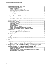
... • Intel® Precision Cooling Technology fan speed control • Voltage sensing to detect out of range values Related Links For more information about Intel Desktop Board D955XCS, including the...Intel Desktop Board D955XCS Product Guide Table 1. Feature Summary (continued) Peripheral Interfaces • One front panel audio header (yellow) • Up to eight USB 2.0 ports ⎯ Four ports routed to the back panel ⎯ Four ports routed to two USB headers • Up to : http://support.intel.com/support/motherboards/desktop/ Supported Operating Systems The desktop board...
... • Intel® Precision Cooling Technology fan speed control • Voltage sensing to detect out of range values Related Links For more information about Intel Desktop Board D955XCS, including the...Intel Desktop Board D955XCS Product Guide Table 1. Feature Summary (continued) Peripheral Interfaces • One front panel audio header (yellow) • Up to eight USB 2.0 ports ⎯ Four ports routed to the back panel ⎯ Four ports routed to two USB headers • Up to : http://support.intel.com/support/motherboards/desktop/ Supported Operating Systems The desktop board...
Product Guide
Page 12
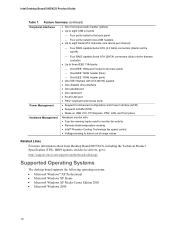
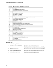
...) Processor fan header (4-pin, fan speed control) Rear chassis fan header (fan speed control) IDE connector Chassis intrusion header Related Links Go to the following links for more information about: • Intel Desktop Board D955XCS http://www.intel.com/design/motherbd http://support.intel.com/support/motherboards/desktop • Supported processors http://support.intel.com/support/motherboards/desktop • Audio software and utilities...
...) Processor fan header (4-pin, fan speed control) Rear chassis fan header (fan speed control) IDE connector Chassis intrusion header Related Links Go to the following links for more information about: • Intel Desktop Board D955XCS http://www.intel.com/design/motherbd http://support.intel.com/support/motherboards/desktop • Supported processors http://support.intel.com/support/motherboards/desktop • Audio software and utilities...
Product Guide
Page 17
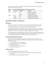
.../100 protocols • Laser Servo (LS-120) drives Serial ATA The desktop board supports eight Serial ATA channels: • Four via the ICH7R, connecting one device per channel in the BIOS reverts all USB 2.0 ports to two internal USB 2.0 headers. Hi-Speed USB 2.0 Support NOTE Computer systems that meets the requirements for a full...
.../100 protocols • Laser Servo (LS-120) drives Serial ATA The desktop board supports eight Serial ATA channels: • Four via the ICH7R, connecting one device per channel in the BIOS reverts all USB 2.0 ports to two internal USB 2.0 headers. Hi-Speed USB 2.0 Support NOTE Computer systems that meets the requirements for a full...
Product Guide
Page 19
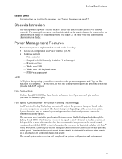
... enabled (default BIOS setting) when using the processor fan heat-sink included with Intel® boxed processors. The processor and chassis fan speed control features can be disabled if a self-controlled chassis fan is implemented at full speed. Fan Connectors Desktop Board D955XCS has three chassis fan headers (two 3-pin and one 4-pin) and one processor...
... enabled (default BIOS setting) when using the processor fan heat-sink included with Intel® boxed processors. The processor and chassis fan speed control features can be disabled if a self-controlled chassis fan is implemented at full speed. Fan Connectors Desktop Board D955XCS has three chassis fan headers (two 3-pin and one 4-pin) and one processor...
Product Guide
Page 32
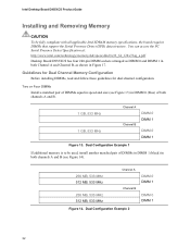
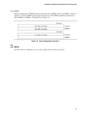
Two or Four DIMMs Install a matched pair of DIMMs equal in speed and size (see Figure 14). 256 MB, 533 MHz 512 MB, 533 MHz 256 MB, 533 MHz 512 MB, 533 MHz Channel A Channel B DIMM 0 DIMM 1 ...) in Figure 17. Dual Configuration Example 1 If additional memory is to be fully compliant with all applicable Intel SDRAM memory specifications, the board requires DIMMs that support the Serial Presence Detect (SPD) data structure. Intel Desktop Board D955XCS Product Guide Installing and Removing Memory CAUTION To be used, install another matched pair of DIMMs in DIMM...
Two or Four DIMMs Install a matched pair of DIMMs equal in speed and size (see Figure 14). 256 MB, 533 MHz 512 MB, 533 MHz 256 MB, 533 MHz 512 MB, 533 MHz Channel A Channel B DIMM 0 DIMM 1 ...) in Figure 17. Dual Configuration Example 1 If additional memory is to be fully compliant with all applicable Intel SDRAM memory specifications, the board requires DIMMs that support the Serial Presence Detect (SPD) data structure. Intel Desktop Board D955XCS Product Guide Installing and Removing Memory CAUTION To be used, install another matched pair of DIMMs in DIMM...
Product Guide
Page 33
Installing and Replacing Desktop Board Components Three DIMMs Install a matched pair of DIMMs equal in speed and size in DIMM 0 (blue) and DIMM 1 (black) of channel B (see Figure 15). 256 MB, 533 MHz 256 MB, 533 MHz 512 MB, 533 MHz Channel A Channel B DIMM 0 DIMM 1 DIMM 0 DIMM 1 Figure 15. Install a DIMM equal in speed and total size of the DIMMs installed in channel A in single channel memory operation. 33 Dual Configuration Example 3 NOTE All other memory configurations will result in either DIMM 0 or DIMM 1 of channel A.
Installing and Replacing Desktop Board Components Three DIMMs Install a matched pair of DIMMs equal in speed and size in DIMM 0 (blue) and DIMM 1 (black) of channel B (see Figure 15). 256 MB, 533 MHz 256 MB, 533 MHz 512 MB, 533 MHz Channel A Channel B DIMM 0 DIMM 1 DIMM 0 DIMM 1 Figure 15. Install a DIMM equal in speed and total size of the DIMMs installed in channel A in single channel memory operation. 33 Dual Configuration Example 3 NOTE All other memory configurations will result in either DIMM 0 or DIMM 1 of channel A.

Product Guide
Page 41
...no pin) 2 TPA4 TPB_REF 6 TPB8 +12 V (fused) 10 Ground G B IEEE 1394a H TPA1+ 1 2 TPA1- Internal Headers OM17786 41 Installing and Replacing Desktop Board Components Connecting Internal Headers Before connecting cables to the internal headers, observe the precautions in "Before You Begin" on page 23. D+ 5 6 D+ Ground 7 8 ...LED E J 31 C Item A B C D E F Description Front panel audio IEEE 1394a Alternate power LED IEEE 1394b Front panel Hi-speed USB Figure 22. A FP Audio Port1L Port1R Port2R Sense_Send Port2L 12 34 56 7 9 10 GND Presence# Sense1_Ret Key (no pin) Sense2_Ret...
...no pin) 2 TPA4 TPB_REF 6 TPB8 +12 V (fused) 10 Ground G B IEEE 1394a H TPA1+ 1 2 TPA1- Internal Headers OM17786 41 Installing and Replacing Desktop Board Components Connecting Internal Headers Before connecting cables to the internal headers, observe the precautions in "Before You Begin" on page 23. D+ 5 6 D+ Ground 7 8 ...LED E J 31 C Item A B C D E F Description Front panel audio IEEE 1394a Alternate power LED IEEE 1394b Front panel Hi-speed USB Figure 22. A FP Audio Port1L Port1R Port2R Sense_Send Port2L 12 34 56 7 9 10 GND Presence# Sense1_Ret Key (no pin) Sense2_Ret...
Product Guide
Page 44
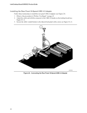
Connecting the Rear Panel Hi-Speed USB 2.0 Adapter 44 Secure the cable's metal bracket to the chassis back panel with the connector to install the rear panel USB 2.0 adapter (see Figure 23, 2). 2 1 OM17787 Figure 23. Intel Desktop Board D955XCS Product Guide Installing the Rear Panel Hi-Speed USB 2.0 Adapter Follow these instructions to the USB 2.0 header on page 23. 2. Attach the cable end with a screw see Figure 23): 1. Observe the precautions in "Before You Begin" on the desktop board (see Figure 23, 1). 3.
Connecting the Rear Panel Hi-Speed USB 2.0 Adapter 44 Secure the cable's metal bracket to the chassis back panel with the connector to install the rear panel USB 2.0 adapter (see Figure 23, 2). 2 1 OM17787 Figure 23. Intel Desktop Board D955XCS Product Guide Installing the Rear Panel Hi-Speed USB 2.0 Adapter Follow these instructions to the USB 2.0 header on page 23. 2. Attach the cable end with a screw see Figure 23): 1. Observe the precautions in "Before You Begin" on the desktop board (see Figure 23, 1). 3.
