Product Guide
Page 3
... product features 2 Installing and Replacing Desktop Board Components: instructions on how to install the desktop board and other environments, such as medical, industrial, alarm systems, test equipment, etc. Use Only for Intel® Desktop Board D946GZTS. It is intended for general audiences. The suitability of this manual: CAUTION Cautions warn the user about board layout, component installation, BIOS update, and regulatory requirements for Intended Applications All Intel® desktop boards are used in this...
... product features 2 Installing and Replacing Desktop Board Components: instructions on how to install the desktop board and other environments, such as medical, industrial, alarm systems, test equipment, etc. Use Only for Intel® Desktop Board D946GZTS. It is intended for general audiences. The suitability of this manual: CAUTION Cautions warn the user about board layout, component installation, BIOS update, and regulatory requirements for Intended Applications All Intel® desktop boards are used in this...

Product Guide
Page 5
... 10 Desktop Board Components 11 Processor ...13 Main Memory ...13 Intel® 946GZ Express Chipset 14 Onboard Audio Subsystem 14 Input/Output (I/O) Controller 15 LAN Subsystem 15 LAN Subsystem Software 15 RJ-45 LAN Connector LEDs 16 Hi-Speed USB 2.0 Support 16 Enhanced IDE Interface 17 Serial ATA ...17 Expandability...17 BIOS ...17 Serial ATA and IDE Auto Configuration 17 PCI and PCI Express* Auto Configuration 18 Security Passwords 18 Hardware Management Features 18 Hardware Monitoring and Fan Speed Control 18 Chassis Intrusion Detection 19 Power Management Features 19 ACPI...
... 10 Desktop Board Components 11 Processor ...13 Main Memory ...13 Intel® 946GZ Express Chipset 14 Onboard Audio Subsystem 14 Input/Output (I/O) Controller 15 LAN Subsystem 15 LAN Subsystem Software 15 RJ-45 LAN Connector LEDs 16 Hi-Speed USB 2.0 Support 16 Enhanced IDE Interface 17 Serial ATA ...17 Expandability...17 BIOS ...17 Serial ATA and IDE Auto Configuration 17 PCI and PCI Express* Auto Configuration 18 Security Passwords 18 Hardware Management Features 18 Hardware Monitoring and Fan Speed Control 18 Chassis Intrusion Detection 19 Power Management Features 19 ACPI...
Product Guide
Page 6
... and Power Cables 49 Connecting Chassis Fan Cables 49 Connecting Power Cables 50 Other Connectors and Headers 51 Setting the BIOS Configuration Jumper 52 Clearing Passwords 53 Back Panel Connectors 54 3 Updating the BIOS Updating the BIOS with the Intel® Express BIOS Update Utility 61 Updating the BIOS with the ISO Image BIOS Update File or the Iflash Memory Update Utility 62 Obtaining the BIOS Update File 62 Updating the BIOS with the ISO Image BIOS Update File 62 Updating the BIOS with Iflash 63 Recovering the BIOS 64 A Error Messages and Indicators BIOS Beep Codes 65 BIOS...
... and Power Cables 49 Connecting Chassis Fan Cables 49 Connecting Power Cables 50 Other Connectors and Headers 51 Setting the BIOS Configuration Jumper 52 Clearing Passwords 53 Back Panel Connectors 54 3 Updating the BIOS Updating the BIOS with the Intel® Express BIOS Update Utility 61 Updating the BIOS with the ISO Image BIOS Update File or the Iflash Memory Update Utility 62 Obtaining the BIOS Update File 62 Updating the BIOS with the ISO Image BIOS Update File 62 Updating the BIOS with Iflash 63 Recovering the BIOS 64 A Error Messages and Indicators BIOS Beep Codes 65 BIOS...
Product Guide
Page 7
... 18. Installing a PCI Express x16 Card 39 20. Connecting the IDE Cable 42 22. Location of Standby Power Indicator 21 4. Beep Codes 65 12. EMC Regulations 73 16. Removing the Battery 59 Tables 1. Install the Processor 30 11. Removing a PCI Express x16 Card 40 21. Front Panel Audio Header Signal Names for the BIOS Setup Program Modes 53 11. Front Panel Header 46 8. Jumper Settings for Intel High Definition Audio 45 5. Lead-Free Board Markings 72 15. Desktop Board D946GZTS Mounting Screw Hole Locations 27 6. Lift the Load Plate...
... 18. Installing a PCI Express x16 Card 39 20. Connecting the IDE Cable 42 22. Location of Standby Power Indicator 21 4. Beep Codes 65 12. EMC Regulations 73 16. Removing the Battery 59 Tables 1. Install the Processor 30 11. Removing a PCI Express x16 Card 40 21. Front Panel Audio Header Signal Names for the BIOS Setup Program Modes 53 11. Front Panel Header 46 8. Jumper Settings for Intel High Definition Audio 45 5. Lead-Free Board Markings 72 15. Desktop Board D946GZTS Mounting Screw Hole Locations 27 6. Lift the Load Plate...
Product Guide
Page 9
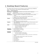
.../100 support (two devices) • One diskette drive interface • One VGA port • One parallel port • One serial port • PS/2* keyboard and mouse ports continued 9 Table 1 summarizes the major features of : • Intel® 946GZ Express Chipset Graphics and Memory Controller Hub (GMCH) • Intel® 82801GB I/O Controller Hub (ICH7) • Intel® 946GZ Express Chipset with Intel® Graphics Media Accelerator 3000 (Intel® GMA 3000) • PCI Express* graphics card support via a PCI Express x16 connector • 6-channel (5.1) onboard...
.../100 support (two devices) • One diskette drive interface • One VGA port • One parallel port • One serial port • PS/2* keyboard and mouse ports continued 9 Table 1 summarizes the major features of : • Intel® 946GZ Express Chipset Graphics and Memory Controller Hub (GMCH) • Intel® 82801GB I/O Controller Hub (ICH7) • Intel® 946GZ Express Chipset with Intel® Graphics Media Accelerator 3000 (Intel® GMA 3000) • PCI Express* graphics card support via a PCI Express x16 connector • 6-channel (5.1) onboard...
Product Guide
Page 10
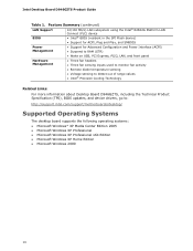
... Advanced Configuration and Power Interface (ACPI) • Suspend to RAM (STR) • Wake on USB, PCI Express, PS/2, LAN, and front panel Hardware Management • Three fan headers • Three fan sensing inputs used to monitor fan activity • Remote diode temperature sensing • Voltage sensing to detect out of range values • Intel® Precision Cooling Technology Related Links: For more information about Desktop Board D946GZTS, including the Technical Product Specification (TPS), BIOS updates, and device drivers...
... Advanced Configuration and Power Interface (ACPI) • Suspend to RAM (STR) • Wake on USB, PCI Express, PS/2, LAN, and front panel Hardware Management • Three fan headers • Three fan sensing inputs used to monitor fan activity • Remote diode temperature sensing • Voltage sensing to detect out of range values • Intel® Precision Cooling Technology Related Links: For more information about Desktop Board D946GZTS, including the Technical Product Specification (TPS), BIOS updates, and device drivers...
Product Guide
Page 12
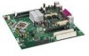
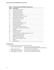
Desktop Board D946GZTS Components Label A B C D E F G H I J K L M N O P Q R S T U V W X Y Description Front panel audio header HD Audio Link header Chassis intrusion header Back panel connectors Hi-speed USB 2.0 headers Main power connector (2 x 12 pin) PCI Express x16 connector PCI Express x1 connector PCI bus connector 1 PCI bus connector 2 BIOS configuration jumper block Diskette drive connector Front panel header Front chassis fan header (3-pin) Alternate front panel power LED header Speaker Serial ATA connectors Processor socket 12 V processor core voltage connector (2 x 2 pin ) ...
Desktop Board D946GZTS Components Label A B C D E F G H I J K L M N O P Q R S T U V W X Y Description Front panel audio header HD Audio Link header Chassis intrusion header Back panel connectors Hi-speed USB 2.0 headers Main power connector (2 x 12 pin) PCI Express x16 connector PCI Express x1 connector PCI bus connector 1 PCI bus connector 2 BIOS configuration jumper block Diskette drive connector Front panel header Front chassis fan header (3-pin) Alternate front panel power LED header Speaker Serial ATA connectors Processor socket 12 V processor core voltage connector (2 x 2 pin ) ...
Product Guide
Page 13
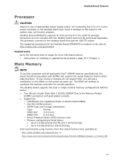
...; Instructions on installing or upgrading the processor, page 28 in the LGA775 package. Desktop Board Features Processor CAUTION Failure to use an appropriate power supply and/or not connecting the 12 V (2 x 2 pin) power connector to the desktop board may not function properly. Processors are not included with the desktop board and must be populated with all applicable Intel® SDRAM memory specifications, the board should be purchased separately. If your memory modules do not support SPD...
...; Instructions on installing or upgrading the processor, page 28 in the LGA775 package. Desktop Board Features Processor CAUTION Failure to use an appropriate power supply and/or not connecting the 12 V (2 x 2 pin) power connector to the desktop board may not function properly. Processors are not included with the desktop board and must be populated with all applicable Intel® SDRAM memory specifications, the board should be purchased separately. If your memory modules do not support SPD...
Product Guide
Page 14
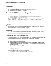
... 6-channel (5.1) onboard audio subsystem that includes a SigmaTel STAC9227 audio codec and an HD Audio Link header. Intel Desktop Board D946GZTS Product Guide Related Links: Go to the following links or pages for more information about : • SDRAM specifications, http://www.intel.com/technology/memory/ • Installing memory, page 35 in card is installed, the GMA 3000 graphics controller is disabled. Either the integrated GMA 3000 graphics controller is required in card can be used or a PCI Express x16...
... 6-channel (5.1) onboard audio subsystem that includes a SigmaTel STAC9227 audio codec and an HD Audio Link header. Intel Desktop Board D946GZTS Product Guide Related Links: Go to the following links or pages for more information about : • SDRAM specifications, http://www.intel.com/technology/memory/ • Installing memory, page 35 in card is installed, the GMA 3000 graphics controller is disabled. Either the integrated GMA 3000 graphics controller is required in card can be used or a PCI Express x16...
Product Guide
Page 15
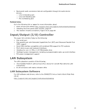
... MB diskette drive • Intelligent power management, including a programmable wake up event interface • PCI power management support LAN Subsystem The LAN subsystem consists of the following: • Intel 82562G Platform LAN Connect (PLC) device for 10/100 Mb/s Ethernet LAN connectivity • RJ-45 connector with status indicator LEDs LAN Subsystem Software For LAN software and drivers, refer to the D946GZTS link on Intel's World Wide Web site at: http://support.intel.com/support/motherboards/desktop 15
... MB diskette drive • Intelligent power management, including a programmable wake up event interface • PCI power management support LAN Subsystem The LAN subsystem consists of the following: • Intel 82562G Platform LAN Connect (PLC) device for 10/100 Mb/s Ethernet LAN connectivity • RJ-45 connector with status indicator LEDs LAN Subsystem Software For LAN software and drivers, refer to the D946GZTS link on Intel's World Wide Web site at: http://support.intel.com/support/motherboards/desktop 15
Product Guide
Page 16
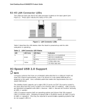
... USB device. Intel Desktop Board D946GZTS Product Guide RJ-45 LAN Connector LEDs Two LEDs are backward compatible with USB 1.1 devices. These LEDs indicate the status of the LAN. Table 3. LAN Connector LED States LED A B LED Color Green Yellow LED State Off On Blinking Off On Indicates LAN link is not established LAN link is established LAN activity is powered up to eight USB 2.0 ports via ICH7 (four ports routed to the back panel and four ports routed to the cable. The desktop board supports...
... USB device. Intel Desktop Board D946GZTS Product Guide RJ-45 LAN Connector LEDs Two LEDs are backward compatible with USB 1.1 devices. These LEDs indicate the status of the LAN. Table 3. LAN Connector LED States LED A B LED Color Green Yellow LED State Off On Blinking Off On Indicates LAN link is not established LAN link is established LAN activity is powered up to eight USB 2.0 ports via ICH7 (four ports routed to the back panel and four ports routed to the cable. The desktop board supports...
Product Guide
Page 17
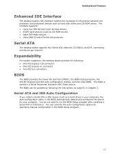
...; One PCI Express x16 connector • One PCI Express x1 connector • Two PCI bus connectors BIOS The BIOS provides the Power-On Self-Test (POST), the BIOS Setup program, the PCI/PCI Express and IDE auto-configuration utilities, and the video BIOS. Serial ATA and IDE Auto Configuration If you install a Serial ATA or IDE device (such as a hard drive) in your computer, the auto-configuration utility in a Serial Peripheral Interface (SPI) Flash device. The interface supports: • Up to run the BIOS Setup program after installing a Serial ATA or IDE device. Desktop Board Features...
...; One PCI Express x16 connector • One PCI Express x1 connector • Two PCI bus connectors BIOS The BIOS provides the Power-On Self-Test (POST), the BIOS Setup program, the PCI/PCI Express and IDE auto-configuration utilities, and the video BIOS. Serial ATA and IDE Auto Configuration If you install a Serial ATA or IDE device (such as a hard drive) in your computer, the auto-configuration utility in a Serial Peripheral Interface (SPI) Flash device. The interface supports: • Up to run the BIOS Setup program after installing a Serial ATA or IDE device. Desktop Board Features...

Product Guide
Page 18
...the BIOS Setup program after you install a PCI/PCI Express add-in card in your computer, the PCI/PCI Express auto-configuration utility in the processor, GMCH, and ICH7 plus an onboard remote sensor • Thermally monitored closed-loop fan control, for a password. Related Links: For instructions on resetting the password, see Clearing Passwords on whether the supervisor or user password was entered. • Setting a user password restricts who can boot the computer. Intel Desktop Board D946GZTS Product Guide PCI and PCI Express* Auto Configuration If you install a PCI/PCI Express...
...the BIOS Setup program after you install a PCI/PCI Express add-in card in your computer, the PCI/PCI Express auto-configuration utility in the processor, GMCH, and ICH7 plus an onboard remote sensor • Thermally monitored closed-loop fan control, for a password. Related Links: For instructions on resetting the password, see Clearing Passwords on whether the supervisor or user password was entered. • Setting a user password restricts who can boot the computer. Intel Desktop Board D946GZTS Product Guide PCI and PCI Express* Auto Configuration If you install a PCI/PCI Express...

Product Guide
Page 19
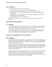
... Configuration and Power Interface (ACPI) • Hardware support: ― Power connectors ― Fan headers ― LAN wake capabilities ― Instantly Available PC technology (Suspend to RAM) ― +5 V standby power indicator LED ― Wake from USB ― Wake from an AC power failure, the computer returns to the chassis intrusion header on page 50 for the location of the power connectors. 19 The computer's response can be connected to the power state it was in the BIOS Setup program's Boot menu...
... Configuration and Power Interface (ACPI) • Hardware support: ― Power connectors ― Fan headers ― LAN wake capabilities ― Instantly Available PC technology (Suspend to RAM) ― +5 V standby power indicator LED ― Wake from USB ― Wake from an AC power failure, the computer returns to the chassis intrusion header on page 50 for the location of the power connectors. 19 The computer's response can be connected to the power state it was in the BIOS Setup program's Boot menu...
Product Guide
Page 20
.... When signaled by the LED turning amber. Failure to provide adequate standby current when using this feature can damage the power supply. Intel Desktop Board D946GZTS Product Guide Fan Headers The function/operation of the fans is as needed. • All fan headers have a +12 V dc connection. Instantly Available PC technology enables the board to support multiple wake events from the PCI and/or USB buses exceeds power supply capacity, the desktop board may lose register settings stored in memory.
.... When signaled by the LED turning amber. Failure to provide adequate standby current when using this feature can damage the power supply. Intel Desktop Board D946GZTS Product Guide Fan Headers The function/operation of the fans is as needed. • All fan headers have a +12 V dc connection. Instantly Available PC technology enables the board to support multiple wake events from the PCI and/or USB buses exceeds power supply capacity, the desktop board may lose register settings stored in memory.

Product Guide
Page 22
.... Intel Desktop Board D946GZTS Product Guide Related Links: For more information on standby current requirements for instructions on the desktop board. Wake from PS/2 Keyboard/Mouse PS/2 keyboard/mouse activity wakes the computer from USB. Speaker A speaker is turned off . Real-Time Clock The desktop board has a time-of a USB peripheral that supports Wake from an ACPI S3 state. The speaker provides audible error code (beep code) information during the Power-On Self-Test (POST). PME# Signal Wake-up Support When the WAKE...
.... Intel Desktop Board D946GZTS Product Guide Related Links: For more information on standby current requirements for instructions on the desktop board. Wake from PS/2 Keyboard/Mouse PS/2 keyboard/mouse activity wakes the computer from USB. Speaker A speaker is turned off . Real-Time Clock The desktop board has a time-of a USB peripheral that supports Wake from an ACPI S3 state. The speaker provides audible error code (beep code) information during the Power-On Self-Test (POST). PME# Signal Wake-up Support When the WAKE...

Product Guide
Page 23
...using an antistatic wrist strap and a conductive foam pad. 2 Installing and Replacing Desktop Board Components This chapter tells you how to: • Install the I/O shield • Install and remove the desktop board • Install and remove a processor • Install and remove memory • Install and remove a PCI Express x16 card • Connect the IDE and Serial ATA cables • Connect to the internal headers • Connect the flexible audio system • Connect the chassis fan and power cables • Set the BIOS configuration jumper • Clear passwords • Replace...
...using an antistatic wrist strap and a conductive foam pad. 2 Installing and Replacing Desktop Board Components This chapter tells you how to: • Install the I/O shield • Install and remove the desktop board • Install and remove a processor • Install and remove memory • Install and remove a PCI Express x16 card • Connect the IDE and Serial ATA cables • Connect to the internal headers • Connect the flexible audio system • Connect the chassis fan and power cables • Set the BIOS configuration jumper • Clear passwords • Replace...

Product Guide
Page 53
... outlet or power adapter). 3. Jumper Settings for the BIOS Setup Program Modes Jumper Setting Mode Description Normal (default) (1-2) The BIOS uses the current configuration and passwords for the BIOS Setup program modes. Place the jumper on pins 1-2 as shown below . 13. Remove the computer cover. 12. Setup displays the maintenance menu again. 9. To restore normal operation, place the jumper on pins 2-3 as shown below . 6. Installing and Replacing Desktop Board Components The three-pin BIOS jumper block enables all peripheral devices connected to normal mode. 1. Turn off all...
... outlet or power adapter). 3. Jumper Settings for the BIOS Setup Program Modes Jumper Setting Mode Description Normal (default) (1-2) The BIOS uses the current configuration and passwords for the BIOS Setup program modes. Place the jumper on pins 1-2 as shown below . 13. Remove the computer cover. 12. Setup displays the maintenance menu again. 9. To restore normal operation, place the jumper on pins 2-3 as shown below . 6. Installing and Replacing Desktop Board Components The three-pin BIOS jumper block enables all peripheral devices connected to normal mode. 1. Turn off all...

Product Guide
Page 61
... of use of Windows-based installation wizards. This is required. To update the BIOS with the Intel® Express BIOS Update Utility With the Intel Express BIOS Update utility you how to update the BIOS by pressing the key after the Power-On Self-Test (POST) memory test begins and before the operating system boot begins. Close all other applications. Double-click the executable file from the location on your hard drive. (You can access the BIOS Setup program...
... of use of Windows-based installation wizards. This is required. To update the BIOS with the Intel® Express BIOS Update Utility With the Intel Express BIOS Update utility you how to update the BIOS by pressing the key after the Power-On Self-Test (POST) memory test begins and before the operating system boot begins. Close all other applications. Double-click the executable file from the location on your hard drive. (You can access the BIOS Setup program...
Product Guide
Page 62
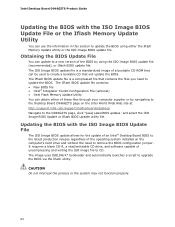
...; Intel® Integrator Toolkit Configuration File (optional) • Intel Flash Memory Update Utility You can be used to create a bootable CD that will update the BIOS. The image uses ISOLINUX* bootloader and automatically launches a script to remove the BIOS configuration jumper. CAUTION Do not interrupt the process or the system may not function properly. 62 It requires a blank CD-R, a read/writeable CD drive, and software capable of a bootable CD-ROM...
...; Intel® Integrator Toolkit Configuration File (optional) • Intel Flash Memory Update Utility You can be used to create a bootable CD that will update the BIOS. The image uses ISOLINUX* bootloader and automatically launches a script to remove the BIOS configuration jumper. CAUTION Do not interrupt the process or the system may not function properly. 62 It requires a blank CD-R, a read/writeable CD drive, and software capable of a bootable CD-ROM...


