
Product Guide
Page 3
...: 1 Desktop Board Features: a summary of product features 2 Installing and Replacing Desktop Board Components: instructions on how to install the desktop board and other hardware components 3 Updating the BIOS: instructions on how to update the BIOS 4 Configuring for RAID (Intel® Matrix Storage Technology) Requires Microsoft Windows* XP or 2000 and SATA Hard Drive(s): information about configuring your system for RAID A Error Messages and Indicators: information about how to prevent damage to important information. iii Intended Uses All Intel desktop boards are used...
...: 1 Desktop Board Features: a summary of product features 2 Installing and Replacing Desktop Board Components: instructions on how to install the desktop board and other hardware components 3 Updating the BIOS: instructions on how to update the BIOS 4 Configuring for RAID (Intel® Matrix Storage Technology) Requires Microsoft Windows* XP or 2000 and SATA Hard Drive(s): information about configuring your system for RAID A Error Messages and Indicators: information about how to prevent damage to important information. iii Intended Uses All Intel desktop boards are used...

Product Guide
Page 5
... BIOS ...22 Serial ATA and IDE Auto Configuration 22 PCI and PCI Express Auto Configuration 22 Security Passwords ...22 Chassis Intrusion...23 Power Management Features 23 ACPI...23 Power Connectors...23 Fan Connectors...23 Fan Speed Control (Intel® Precision Cooling Technology 23 Suspend to RAM (Instantly Available PC Technology 24 Wake from USB...24 Wake from PS/2 Keyboard/Mouse 25 PME# Wakeup Support 25 Speaker...25 Battery...25 Real-Time Clock...25 2 Installing and Replacing Desktop Board Components Before You Begin ...27 Installation Precautions ...28 Installation Instructions...
... BIOS ...22 Serial ATA and IDE Auto Configuration 22 PCI and PCI Express Auto Configuration 22 Security Passwords ...22 Chassis Intrusion...23 Power Management Features 23 ACPI...23 Power Connectors...23 Fan Connectors...23 Fan Speed Control (Intel® Precision Cooling Technology 23 Suspend to RAM (Instantly Available PC Technology 24 Wake from USB...24 Wake from PS/2 Keyboard/Mouse 25 PME# Wakeup Support 25 Speaker...25 Battery...25 Real-Time Clock...25 2 Installing and Replacing Desktop Board Components Before You Begin ...27 Installation Precautions ...28 Installation Instructions...
Product Guide
Page 6
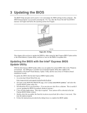
...(Optional 47 Connecting Fan and Power Cables 48 Connecting Fan Cables 48 Connecting Power Cables 49 Other Connectors...50 Setting the BIOS Configuration Jumper 51 Clearing Passwords ...52 3 Updating the BIOS Updating the BIOS with the Intel® Express BIOS Update Utility 59 Updating the BIOS with the Iflash Memory Update Utility 60 Obtaining the BIOS Update File 60 Updating the BIOS...60 Recovering the BIOS 61 4 Configuring for Intel Matrix Storage Technology 63 Creating Your RAID Set 63 Loading the Intel Matrix Storage Technology RAID Drivers and Software 64 Setting Up a "RAID...
...(Optional 47 Connecting Fan and Power Cables 48 Connecting Fan Cables 48 Connecting Power Cables 49 Other Connectors...50 Setting the BIOS Configuration Jumper 51 Clearing Passwords ...52 3 Updating the BIOS Updating the BIOS with the Intel® Express BIOS Update Utility 59 Updating the BIOS with the Iflash Memory Update Utility 60 Obtaining the BIOS Update File 60 Updating the BIOS...60 Recovering the BIOS 61 4 Configuring for Intel Matrix Storage Technology 63 Creating Your RAID Set 63 Loading the Intel Matrix Storage Technology RAID Drivers and Software 64 Setting Up a "RAID...

Product Guide
Page 7
... Cable to the Processor Fan Connector ........35 14. Inserting a PCI Express x16 Card and Covering the Back Panel VGA Port 40 19. Connecting the IDE Cable 41 20. Lift the Load Plate and Don't Touch the Socket Contacts 32 9. Remove the Protective Socket Cover 33 10. Close the Load Plate ...34 13. Dual Configuration Example 2 36 16. Location of Other Connectors on Desktop Board D945GNT/D945GTP 50 26. Location of Fan Headers 48 24. Desktop Board D945GNT Components 12 2. Internal Headers...
... Cable to the Processor Fan Connector ........35 14. Inserting a PCI Express x16 Card and Covering the Back Panel VGA Port 40 19. Connecting the IDE Cable 41 20. Lift the Load Plate and Don't Touch the Socket Contacts 32 9. Remove the Protective Socket Cover 33 10. Close the Load Plate ...34 13. Dual Configuration Example 2 36 16. Location of Other Connectors on Desktop Board D945GNT/D945GTP 50 26. Location of Fan Headers 48 24. Desktop Board D945GNT Components 12 2. Internal Headers...
Product Guide
Page 9
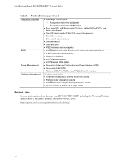
....com/support/motherboards/desktop/ Intel® 945G Express Chipset consisting of: • Intel® 82945G Graphics and Memory Controller Hub (GMCH) with Direct Media Interface • Intel® 82801GB I/O Controller Hub (ICH7) or 82801GR I/O Controller Hub (ICH7R) supporting Intel® Matrix Storage Technology • Firmware Hub (FWH) Intel 945G Express Chipset with Intel® Graphics Media Accelerator 950 • Intel 945G Express Chipset • Intel® High Definition Audio interface • SigmaTel* codec Desktop board D945GNT: • Four PCI bus add-in card connectors...
....com/support/motherboards/desktop/ Intel® 945G Express Chipset consisting of: • Intel® 82945G Graphics and Memory Controller Hub (GMCH) with Direct Media Interface • Intel® 82801GB I/O Controller Hub (ICH7) or 82801GR I/O Controller Hub (ICH7R) supporting Intel® Matrix Storage Technology • Firmware Hub (FWH) Intel 945G Express Chipset with Intel® Graphics Media Accelerator 950 • Intel 945G Express Chipset • Intel® High Definition Audio interface • SigmaTel* codec Desktop board D945GNT: • Four PCI bus add-in card connectors...
Product Guide
Page 10
... support (two devices) • One VGA connector • One diskette drive interface • One parallel port BIOS • One serial port • PS/2* keyboard and mouse ports • Intel® Platform Innovation Framework for extensible firmware interface • 4 Mbit symmetrical flash memory • Support for SMBIOS • Intel® Rapid BIOS Boot • Intel® Express BIOS Update Power Management • Support for Advanced Configuration and Power Interface (ACPI) • Suspend to RAM (STR) • Wake on USB, PCI, PCI Express, PS/2, LAN, and front panel...
... support (two devices) • One VGA connector • One diskette drive interface • One parallel port BIOS • One serial port • PS/2* keyboard and mouse ports • Intel® Platform Innovation Framework for extensible firmware interface • 4 Mbit symmetrical flash memory • Support for SMBIOS • Intel® Rapid BIOS Boot • Intel® Express BIOS Update Power Management • Support for Advanced Configuration and Power Interface (ACPI) • Suspend to RAM (STR) • Wake on USB, PCI, PCI Express, PS/2, LAN, and front panel...
Product Guide
Page 13
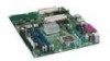
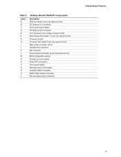
..., fan speed control) PCI Express x1 connectors Front panel audio header PCI Express x16 connector 12 V processor core voltage connector (2x2) Rear chassis fan header 1 (3-pin, fan speed control) Processor socket Processor fan header (4-pin, fan speed control) Main power connector (2x12) Diskette drive connector IDE connector Front chassis fan header (3-pin, fan speed control) BIOS configuration jumper Chassis intrusion header Serial ATA connectors Front panel header Alternate power LED header Hi-speed USB 2.0 headers IEEE 1394a headers (optional) PCI bus add-in card connectors Desktop Board...
..., fan speed control) PCI Express x1 connectors Front panel audio header PCI Express x16 connector 12 V processor core voltage connector (2x2) Rear chassis fan header 1 (3-pin, fan speed control) Processor socket Processor fan header (4-pin, fan speed control) Main power connector (2x12) Diskette drive connector IDE connector Front chassis fan header (3-pin, fan speed control) BIOS configuration jumper Chassis intrusion header Serial ATA connectors Front panel header Alternate power LED header Hi-speed USB 2.0 headers IEEE 1394a headers (optional) PCI bus add-in card connectors Desktop Board...

Product Guide
Page 15
...S Desktop Boards D945GTP Components Description Front panel audio header PCI bus add-in card connectors PCI Express x16 connector 12 V processor core voltage connector (2x2) Rear fan (3-pin, fan speed control) Processor socket Processor fan header (4-pin, fan speed control) Main power connector (2x12) Diskette drive connector IDE connector Front chassis fan header (fan speed control) BIOS configuration jumper Chassis intrusion header Serial ATA connectors Front panel header Alternate power LED header Hi-speed USB 2.0 headers IEEE 1394 headers (optional) PCI Express x1 connector Related Links...
...S Desktop Boards D945GTP Components Description Front panel audio header PCI bus add-in card connectors PCI Express x16 connector 12 V processor core voltage connector (2x2) Rear fan (3-pin, fan speed control) Processor socket Processor fan header (4-pin, fan speed control) Main power connector (2x12) Diskette drive connector IDE connector Front chassis fan header (fan speed control) BIOS configuration jumper Chassis intrusion header Serial ATA connectors Front panel header Alternate power LED header Hi-speed USB 2.0 headers IEEE 1394 headers (optional) PCI Express x1 connector Related Links...
Product Guide
Page 17
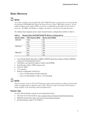
... memory, http://support.intel.com/support/motherboards/desktop/ • SDRAM specifications, http://www.intel.com/technology/memory/ • Installing memory, page 36 in Table 6. Desktop Board Features Main Memory NOTE To be fully compliant with all applicable Intel® SDRAM memory specifications, the board should be populated with gold-plated contacts • Unbuffered, non-registered single or double-sided DIMMs • Serial Presence Detect (SPD) memory only • Non-ECC RAM • 1.8 V memory • Memory configuration listed...
... memory, http://support.intel.com/support/motherboards/desktop/ • SDRAM specifications, http://www.intel.com/technology/memory/ • Installing memory, page 36 in Table 6. Desktop Board Features Main Memory NOTE To be fully compliant with all applicable Intel® SDRAM memory specifications, the board should be populated with gold-plated contacts • Unbuffered, non-registered single or double-sided DIMMs • Serial Presence Detect (SPD) memory only • Non-ECC RAM • 1.8 V memory • Memory configuration listed...

Product Guide
Page 19
Desktop Board Features Related Links: Go to the following link or pages for more information about: • Audio drivers and utilities http://support.intel.com/support/motherboards/desktop/ • Installing the front panel audio solution, page 44 in Chapter 2 • The location of audio connectors, Figure 22 on page 47 Input/Output (I/O) Controller The super I/O controller features the following: • One serial port • One parallel port with Extended Capabilities Port (ECP) and...
Desktop Board Features Related Links: Go to the following link or pages for more information about: • Audio drivers and utilities http://support.intel.com/support/motherboards/desktop/ • Installing the front panel audio solution, page 44 in Chapter 2 • The location of audio connectors, Figure 22 on page 47 Input/Output (I/O) Controller The super I/O controller features the following: • One serial port • One parallel port with Extended Capabilities Port (ECP) and...
Product Guide
Page 21
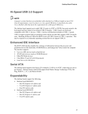
...processor and peripheral devices like hard disks, CD-ROM drives, and Iomega Zip* drives inside the computer. USB 2.0 ports are backward compatible with ICH7R support Intel Matrix Storage Technology (NCQ, Hot Plug, RAID 0, 1, 10, 5, and Matrix RAID). Use a shielded cable that fully support USB 2.0 transfer rates. USB 1.1 devices will function normally at USB 1.1 speeds. Expandability The desktop boards support the following: • Desktop board D945GNT: ⎯ One PCI Express x16 add-in card ⎯ Two PCI Express x1 add-in cards ⎯ Four PCI add-in cards • Desktop...
...processor and peripheral devices like hard disks, CD-ROM drives, and Iomega Zip* drives inside the computer. USB 2.0 ports are backward compatible with ICH7R support Intel Matrix Storage Technology (NCQ, Hot Plug, RAID 0, 1, 10, 5, and Matrix RAID). Use a shielded cable that fully support USB 2.0 transfer rates. USB 1.1 devices will function normally at USB 1.1 speeds. Expandability The desktop boards support the following: • Desktop board D945GNT: ⎯ One PCI Express x16 add-in card ⎯ Two PCI Express x1 add-in cards ⎯ Four PCI add-in cards • Desktop...

Product Guide
Page 22
... BIOS Setup program can be accessed and who can be updated by specifying manual configuration in the Firmware Hub. The password prompt is displayed before the computer is set , you can boot the computer. PCI and PCI Express Auto Configuration If you install a Serial ATA or IDE device (such as a hard drive) in your computer. Intel Desktop Board D945GNT/D945GTP Product Guide Related Links: For information about installing the PCI Express x16 card, see Clearing Passwords on whether the supervisor or user password was entered...
... BIOS Setup program can be accessed and who can be updated by specifying manual configuration in the Firmware Hub. The password prompt is displayed before the computer is set , you can boot the computer. PCI and PCI Express Auto Configuration If you install a Serial ATA or IDE device (such as a hard drive) in your computer. Intel Desktop Board D945GNT/D945GTP Product Guide Related Links: For information about installing the PCI Express x16 card, see Clearing Passwords on whether the supervisor or user password was entered...
Product Guide
Page 23
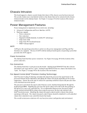
... location of the power connectors. Desktop board D945GNT has three chassis fan headers (one 4-pin and two 3-pin). Fan Connectors The desktop board has a 4-pin processor fan header. See Figure 23 on system configuration and environment. 23 The chassis fan speed control feature should be disabled if a self-controlled chassis fan is recommended that provides full ACPI support. See Figure 24 on the chassis that detects if the chassis cover has been removed. It is attached to RAM (Instantly Available PC technology) ⎯ Wake from USB...
... location of the power connectors. Desktop board D945GNT has three chassis fan headers (one 4-pin and two 3-pin). Fan Connectors The desktop board has a 4-pin processor fan header. See Figure 23 on system configuration and environment. 23 The chassis fan speed control feature should be disabled if a self-controlled chassis fan is recommended that provides full ACPI support. See Figure 24 on the chassis that detects if the chassis cover has been removed. It is attached to RAM (Instantly Available PC technology) ⎯ Wake from USB...

Product Guide
Page 24
... PC technology enables the board to enter the ACPI S3 (Suspend-to be off . Failure to RAM (Instantly Available PC Technology) CAUTIONS For Instantly Available PC technology, the 5 V standby line for the desktop board, refer to the Technical Product Specification by the LED turning amber. Intel Desktop Board D945GNT/D945GTP Product Guide Suspend to provide adequate standby current when using this desktop board must be capable of a USB peripheral that supports wake from an ACPI...
... PC technology enables the board to enter the ACPI S3 (Suspend-to be off . Failure to RAM (Instantly Available PC Technology) CAUTIONS For Instantly Available PC technology, the 5 V standby line for the desktop board, refer to the Technical Product Specification by the LED turning amber. Intel Desktop Board D945GNT/D945GTP Product Guide Suspend to provide adequate standby current when using this desktop board must be capable of a USB peripheral that supports wake from an ACPI...

Product Guide
Page 27
...Refer to operate even though the front panel power button is off. Failure to : • Install the I/O shield • Install and remove the desktop board • Install and remove a processor and memory • Install and remove a PCI Express x16 card • Connect the IDE and Serial ATA cables • Connect internal headers • Set up flexible 6-channel audio with jack re-tasking • Connect fans and power cables • Locate other connectors • Set the BIOS configuration jumper • Clear passwords • Replace the battery Before You Begin CAUTIONS The procedures...
...Refer to operate even though the front panel power button is off. Failure to : • Install the I/O shield • Install and remove the desktop board • Install and remove a processor and memory • Install and remove a PCI Express x16 card • Connect the IDE and Serial ATA cables • Connect internal headers • Set up flexible 6-channel audio with jack re-tasking • Connect fans and power cables • Locate other connectors • Set the BIOS configuration jumper • Clear passwords • Replace the battery Before You Begin CAUTIONS The procedures...

Product Guide
Page 51
... (default) (1-2) Description The BIOS uses the current configuration and passwords for the Setup program modes. Table 14. Table 14 shows the jumper settings for booting. 1 Configure (2-3) After the Power-On Self-Test (POST) runs, the BIOS 3 displays the Maintenance Menu. Figure 26 shows the location of the desktop board's BIOS configuration jumper. 3 2 1 Figure 26. Installing and Replacing Desktop Board Components Setting the BIOS Configuration Jumper NOTE Always turn off the power and unplug the power cord from a recovery diskette in the 3 event of a failed BIOS update...
... (default) (1-2) Description The BIOS uses the current configuration and passwords for the Setup program modes. Table 14. Table 14 shows the jumper settings for booting. 1 Configure (2-3) After the Power-On Self-Test (POST) runs, the BIOS 3 displays the Maintenance Menu. Figure 26 shows the location of the desktop board's BIOS configuration jumper. 3 2 1 Figure 26. Installing and Replacing Desktop Board Components Setting the BIOS Configuration Jumper NOTE Always turn off the power and unplug the power cord from a recovery diskette in the 3 event of a failed BIOS update...

Product Guide
Page 52
Turn off all peripheral devices connected to boot. 7. Disconnect the computer's power cord from the AC power source. 11. Remove the computer cover. 4. Replace the cover, plug in the computer, turn on pins 2-3 as shown below . 3 1 6. Press and Setup displays a pop-up screen requesting that the board is installed in the computer and the configuration jumper block is set to save the current values and exit Setup. 10. Setup displays the maintenance menu again...
Turn off all peripheral devices connected to boot. 7. Disconnect the computer's power cord from the AC power source. 11. Remove the computer cover. 4. Replace the cover, plug in the computer, turn on pins 2-3 as shown below . 3 1 6. Press and Setup displays a pop-up screen requesting that the board is installed in the computer and the configuration jumper block is set to save the current values and exit Setup. 10. Setup displays the maintenance menu again...
Product Guide
Page 59
... using the Intel Express BIOS Update utility or the Iflash Memory Update utility, and how to your hard drive where it was saved. Close all other applications. Double-click the executable file from the location on your hard drive. (You can update the system BIOS while in the dialog boxes to a diskette. F2 OM17050 Figure 28. Navigate to the Intel World Wide Web site: http://support.intel.com/support/motherboards/desktop/ 2. Follow the instructions...
... using the Intel Express BIOS Update utility or the Iflash Memory Update utility, and how to your hard drive where it was saved. Close all other applications. Double-click the executable file from the location on your hard drive. (You can update the system BIOS while in the dialog boxes to a diskette. F2 OM17050 Figure 28. Navigate to the Intel World Wide Web site: http://support.intel.com/support/motherboards/desktop/ 2. Follow the instructions...

Product Guide
Page 63
... BIOS Setup by pressing . Enter a volume name and press . NOTE: The RAID Volume name must be used in the MAIN MENU. 63 Finally, press to the EXIT option in the RAID array (only if there are installed respectively). Upon re-boot, you have selected the RAID LEVEL. 4. Press once you will only appear if three or four SATA drives are more SATA hard drives. 2. Press and enter the RAID Configuration Utility...
... BIOS Setup by pressing . Enter a volume name and press . NOTE: The RAID Volume name must be used in the MAIN MENU. 63 Finally, press to the EXIT option in the RAID array (only if there are installed respectively). Upon re-boot, you have selected the RAID LEVEL. 4. Press once you will only appear if three or four SATA drives are more SATA hard drives. 2. Press and enter the RAID Configuration Utility...

Product Guide
Page 64
... Product Guide Loading the Intel Matrix Storage Technology RAID Drivers and Software 1. Install the Intel 82801GR SATA RAID Controller driver. 3. Install the Intel Matrix Storage Console software via the Intel Express Installer CD included with your desktop board or after downloading it from the Windows installation CD. 2. Once you have added the additional SATA drives, open the Intel Matrix Storage Technology Console Software and follow the directions to update to install a third-party SCSI or RAID driver. Begin Windows Setup by booting from the Internet at http://support.intel...
... Product Guide Loading the Intel Matrix Storage Technology RAID Drivers and Software 1. Install the Intel 82801GR SATA RAID Controller driver. 3. Install the Intel Matrix Storage Console software via the Intel Express Installer CD included with your desktop board or after downloading it from the Windows installation CD. 2. Once you have added the additional SATA drives, open the Intel Matrix Storage Technology Console Software and follow the directions to update to install a third-party SCSI or RAID driver. Begin Windows Setup by booting from the Internet at http://support.intel...


