Product Guide
Page 3
... of product features 2 Installing and Replacing Desktop Board Components: instructions on how to install the desktop board and other environments, such as Information Technology Equipment (I.T.E.) for use in personal computers (PC) for installation in this manual: CAUTION Cautions warn the user about board layout, component installation, BIOS update, and regulatory requirements for Intel® Desktop Board D945GCPE. NOTE Notes call attention to update the BIOS A Error Messages: information about BIOS error messages B Regulatory Compliance: lists safety standards, EMC...
... of product features 2 Installing and Replacing Desktop Board Components: instructions on how to install the desktop board and other environments, such as Information Technology Equipment (I.T.E.) for use in personal computers (PC) for installation in this manual: CAUTION Cautions warn the user about board layout, component installation, BIOS update, and regulatory requirements for Intel® Desktop Board D945GCPE. NOTE Notes call attention to update the BIOS A Error Messages: information about BIOS error messages B Regulatory Compliance: lists safety standards, EMC...

Product Guide
Page 5
... Desktop Board Components 11 Processor ...13 Main Memory...13 Intel® 945GC Express Chipset 14 Onboard Audio Subsystem 14 Input/Output (I/O) Controller 15 LAN Subsystem 15 LAN Subsystem Software 15 RJ-45 LAN Connector LEDs 16 Hi-Speed USB 2.0 Support 16 Enhanced IDE Interface 17 Serial ATA...17 Expandability...17 BIOS ...17 Serial ATA and IDE Auto Configuration 17 PCI* Auto Configuration 18 Security Passwords 18 Hardware Management Features 18 Hardware Monitoring and Fan Speed Control 18 Chassis Intrusion Detection 19 Power Management Features 19 ACPI ...19 Hardware Support...
... Desktop Board Components 11 Processor ...13 Main Memory...13 Intel® 945GC Express Chipset 14 Onboard Audio Subsystem 14 Input/Output (I/O) Controller 15 LAN Subsystem 15 LAN Subsystem Software 15 RJ-45 LAN Connector LEDs 16 Hi-Speed USB 2.0 Support 16 Enhanced IDE Interface 17 Serial ATA...17 Expandability...17 BIOS ...17 Serial ATA and IDE Auto Configuration 17 PCI* Auto Configuration 18 Security Passwords 18 Hardware Management Features 18 Hardware Monitoring and Fan Speed Control 18 Chassis Intrusion Detection 19 Power Management Features 19 ACPI ...19 Hardware Support...

Product Guide
Page 6
Intel Desktop Board D945GCPE Product Guide Connecting the Processor Fan Heat Sink Cable 31 Removing the Processor 31 Installing and Removing Memory 32 Installing DIMMs 34 Removing DIMMs 35 Connecting the Diskette Drive Cable 36 Connecting the IDE Cable 37 Connecting the Serial ATA (SATA) Cable 38 Connecting to Internal Headers 39 Connecting to the Front Panel Audio Header 40 Connecting to the Serial Port Header 41 Connecting to the Chassis Intrusion Header 41 Connecting to the Front Panel Header 42 Connecting to the Alternate Front Panel Power LED Header 42 Connecting to the USB ...
Intel Desktop Board D945GCPE Product Guide Connecting the Processor Fan Heat Sink Cable 31 Removing the Processor 31 Installing and Removing Memory 32 Installing DIMMs 34 Removing DIMMs 35 Connecting the Diskette Drive Cable 36 Connecting the IDE Cable 37 Connecting the Serial ATA (SATA) Cable 38 Connecting to Internal Headers 39 Connecting to the Front Panel Audio Header 40 Connecting to the Serial Port Header 41 Connecting to the Chassis Intrusion Header 41 Connecting to the Front Panel Header 42 Connecting to the Alternate Front Panel Power LED Header 42 Connecting to the USB ...

Product Guide
Page 7
...Connecting the IDE Cable 37 18. Back Panel Audio Connectors 43 21. Serial Port Header Signal Names 41 7. Installing the I/O Shield 25 5. Remove the Protective Socket Cover 28 9. Installing a DIMM 34 16. Connecting the Serial ATA Cable 38 19. Location of the BIOS Configuration Jumper Block 46 24. Removing the Battery 52 Tables 1. Front Panel Audio Header Signal Names for the BIOS Setup Program Modes 47 12. Contents Figures 1. LAN Connector LEDs 16 3. Close the Load Plate 30 12. Dual Channel Memory Configuration Example 32 14. Connecting Power Supply...
...Connecting the IDE Cable 37 18. Back Panel Audio Connectors 43 21. Serial Port Header Signal Names 41 7. Installing the I/O Shield 25 5. Remove the Protective Socket Cover 28 9. Installing a DIMM 34 16. Connecting the Serial ATA Cable 38 19. Location of the BIOS Configuration Jumper Block 46 24. Removing the Battery 52 Tables 1. Front Panel Audio Header Signal Names for the BIOS Setup Program Modes 47 12. Contents Figures 1. LAN Connector LEDs 16 3. Close the Load Plate 30 12. Dual Channel Memory Configuration Example 32 14. Connecting Power Supply...
Product Guide
Page 9
... I/O Controller Hub (ICH7) Intel 945GC Express Chipset with Intel® Graphics Media Accelerator 950 (Intel® GMA 950) • 4-channel (2 + 2) onboard subsystem, featuring: ― Intel® High Definition Audio interface ― Realtek* ALC662 audio codec Two PCI* connectors • Up to eight USB 2.0 ports ― Four ports routed to the back panel ― Four ports routed to two USB headers • Two Serial ATA (SATA) channels (3.0 Gb/s), via the ICH7, one device per channel • One IDE interface...
... I/O Controller Hub (ICH7) Intel 945GC Express Chipset with Intel® Graphics Media Accelerator 950 (Intel® GMA 950) • 4-channel (2 + 2) onboard subsystem, featuring: ― Intel® High Definition Audio interface ― Realtek* ALC662 audio codec Two PCI* connectors • Up to eight USB 2.0 ports ― Four ports routed to the back panel ― Four ports routed to two USB headers • Two Serial ATA (SATA) channels (3.0 Gb/s), via the ICH7, one device per channel • One IDE interface...
Product Guide
Page 10
.../2, LAN, and front panel • ENERGY STAR* capable Hardware Management • Two fan headers • Two fan sensing inputs used to monitor fan activity • Remote diode temperature sensing • Voltage sensing to detect out of range values • Integrated SIO fan control Related Links: For more information about Desktop Board D945GCPE, including the Technical Product Specification (TPS), BIOS updates, and device drivers, go to: http://support.intel.com/support/motherboards/desktop/ Supported Operating Systems The desktop board supports...
.../2, LAN, and front panel • ENERGY STAR* capable Hardware Management • Two fan headers • Two fan sensing inputs used to monitor fan activity • Remote diode temperature sensing • Voltage sensing to detect out of range values • Integrated SIO fan control Related Links: For more information about Desktop Board D945GCPE, including the Technical Product Specification (TPS), BIOS updates, and device drivers, go to: http://support.intel.com/support/motherboards/desktop/ Supported Operating Systems The desktop board supports...
Product Guide
Page 12
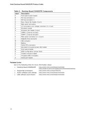
... pin) Diskette drive connector IDE connector Battery Serial ATA connectors Alternate front panel power LED header Front panel header BIOS configuration jumper block Chassis intrusion header Hi-speed USB 2.0 headers Serial port header Related Links: Go to the following links for more information about: • Desktop Board D945GCPE http://www.intel.com/design/motherbd http://support.intel.com/support/motherboards/desktop • Supported processors http://www.intel.com/go/FindCPU • Audio software and utilities http://www.intel.com/design/motherbd • LAN software and drivers...
... pin) Diskette drive connector IDE connector Battery Serial ATA connectors Alternate front panel power LED header Front panel header BIOS configuration jumper block Chassis intrusion header Hi-speed USB 2.0 headers Serial port header Related Links: Go to the following links for more information about: • Desktop Board D945GCPE http://www.intel.com/design/motherbd http://support.intel.com/support/motherboards/desktop • Supported processors http://www.intel.com/go/FindCPU • Audio software and utilities http://www.intel.com/design/motherbd • LAN software and drivers...
Product Guide
Page 13
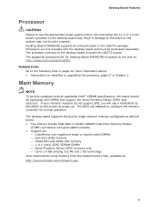
... specifications, the board should be populated with the desktop board and must be purchased separately. The supported processors list for Desktop Board D945GCPE is located on the web at: http://www.intel.com/go/FindCPU Related Links: Go to 2.0 GB utilizing 512 Mb and 1 Gb technology Intel recommends using memory from the tested memory lists, available at power up. Desktop Board Features Processor CAUTION Failure to use the appropriate power supply and/or not connecting the 12 V (2 x 2 pin) power connector to...
... specifications, the board should be populated with the desktop board and must be purchased separately. The supported processors list for Desktop Board D945GCPE is located on the web at: http://www.intel.com/go/FindCPU Related Links: Go to 2.0 GB utilizing 512 Mb and 1 Gb technology Intel recommends using memory from the tested memory lists, available at power up. Desktop Board Features Processor CAUTION Failure to use the appropriate power supply and/or not connecting the 12 V (2 x 2 pin) power connector to...
Product Guide
Page 15
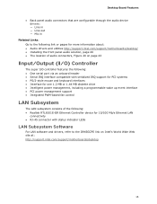
... power management, including a programmable wake up event interface • PCI power management support • Integrated PWM-based fan control LAN Subsystem The LAN subsystem consists of the following: • Realtek RTL8101E-GR Ethernet Controller device for 10/100 Mb/s Ethernet LAN connectivity • RJ-45 connector with status indicator LEDs LAN Subsystem Software For LAN software and drivers, refer to the D945GCPE link on Intel's World Wide Web site at: http://support.intel.com/support/motherboards/desktop...
... power management, including a programmable wake up event interface • PCI power management support • Integrated PWM-based fan control LAN Subsystem The LAN subsystem consists of the following: • Realtek RTL8101E-GR Ethernet Controller device for 10/100 Mb/s Ethernet LAN connectivity • RJ-45 connector with status indicator LEDs LAN Subsystem Software For LAN software and drivers, refer to the D945GCPE link on Intel's World Wide Web site at: http://support.intel.com/support/motherboards/desktop...
Product Guide
Page 16
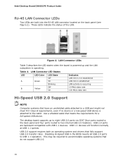
... is not established LAN link is established LAN activity is occurring 10 Mb/s data rate 100 Mb/s data rate Hi-Speed USB 2.0 Support NOTE Computer systems that do not support USB 2.0. 16 USB 1.1 devices will function normally at USB 1.1 speeds. Use a shielded cable that fully support USB 2.0 transfer rates. Intel Desktop Board D945GCPE Product Guide RJ-45 LAN Connector LEDs Two LEDs are backward compatible with USB 1.1 devices. The desktop board supports up and the LAN subsystem is attached to two internal USB 2.0 headers).
... is not established LAN link is established LAN activity is occurring 10 Mb/s data rate 100 Mb/s data rate Hi-Speed USB 2.0 Support NOTE Computer systems that do not support USB 2.0. 16 USB 1.1 devices will function normally at USB 1.1 speeds. Use a shielded cable that fully support USB 2.0 transfer rates. Intel Desktop Board D945GCPE Product Guide RJ-45 LAN Connector LEDs Two LEDs are backward compatible with USB 1.1 devices. The desktop board supports up and the LAN subsystem is attached to two internal USB 2.0 headers).

Product Guide
Page 17
... desktop board provides two PCI bus connectors. The BIOS can override the auto-configuration options by following the instructions on page 53 in the BIOS Setup program. 17 You do not need to two IDE devices (such as hard drives) • ATAPI-style devices (such as hard disk drives and CD-ROM drives. You can be updated by specifying manual configuration in Chapter 3. BIOS The BIOS provides the Power-On Self-Test (POST), the BIOS Setup program, the PCI and IDE auto-configuration utilities, and the video BIOS...
... desktop board provides two PCI bus connectors. The BIOS can override the auto-configuration options by following the instructions on page 53 in the BIOS Setup program. 17 You do not need to two IDE devices (such as hard drives) • ATAPI-style devices (such as hard disk drives and CD-ROM drives. You can be updated by specifying manual configuration in Chapter 3. BIOS The BIOS provides the Power-On Self-Test (POST), the BIOS Setup program, the PCI and IDE auto-configuration utilities, and the video BIOS...

Product Guide
Page 18
... following: • Fan speed monitoring and control • Thermal and voltage monitoring • Chassis intrusion detection Hardware Monitoring and Fan Speed Control The features of the hardware monitoring and fan speed control include: • Monitoring of Setup gives the user restricted access to Setup. • If both passwords are set , the computer boots without asking for all Setup options. Intel Desktop Board D945GCPE Product Guide PCI* Auto Configuration If you install a PCI add-in card in your computer, the PCI auto-configuration utility in the BIOS automatically detects and...
... following: • Fan speed monitoring and control • Thermal and voltage monitoring • Chassis intrusion detection Hardware Monitoring and Fan Speed Control The features of the hardware monitoring and fan speed control include: • Monitoring of Setup gives the user restricted access to Setup. • If both passwords are set , the computer boots without asking for all Setup options. Intel Desktop Board D945GCPE Product Guide PCI* Auto Configuration If you install a PCI add-in card in your computer, the PCI auto-configuration utility in the BIOS automatically detects and...
Product Guide
Page 19
... Configuration and Power Interface (ACPI) • Hardware support: ― Power connectors ― Fan headers ― LAN wake capabilities ― Instantly Available PC technology (Suspend to the power state it was in the BIOS Setup program's Boot menu. The use of the chassis intrusion header. Hardware Support Power Connectors ATX12V-compliant power supplies can be connected to the chassis intrusion header on the chassis that provides full ACPI support. The computer's response can turn off ). The desktop board has two power connectors. Desktop Board Features Chassis...
... Configuration and Power Interface (ACPI) • Hardware support: ― Power connectors ― Fan headers ― LAN wake capabilities ― Instantly Available PC technology (Suspend to the power state it was in the BIOS Setup program's Boot menu. The use of the chassis intrusion header. Hardware Support Power Connectors ATX12V-compliant power supplies can be connected to the chassis intrusion header on the chassis that provides full ACPI support. The computer's response can turn off ). The desktop board has two power connectors. Desktop Board Features Chassis...
Product Guide
Page 20
... fan headers have a +12 V dc connection. The desktop board has a 4-pin processor fan header and a 3-pin chassis fan header. Instantly Available PC technology enables the board to enter the ACPI S3 (Suspend-toRAM) sleep state. If the computer has a dual-colored power LED on or off as follows: • The fans are on when the computer is in power management and can adjust the fan speed or switch the fan on the front panel, the sleep state is indicated by a wake...
... fan headers have a +12 V dc connection. The desktop board has a 4-pin processor fan header and a 3-pin chassis fan header. Instantly Available PC technology enables the board to enter the ACPI S3 (Suspend-toRAM) sleep state. If the computer has a dual-colored power LED on or off as follows: • The fans are on when the computer is in power management and can adjust the fan speed or switch the fan on the front panel, the sleep state is indicated by a wake...

Product Guide
Page 23
... as model, serial numbers, installed options, and configuration information. • Electrostatic discharge (ESD) can continue to operate even though the front panel power button is not available, you can provide some ESD protection by wearing an antistatic wrist strap and attaching it to the internal headers • Connect the flexible audio system • Connect the chassis fan and power cables • Set the BIOS configuration jumper • Clear passwords • Replace the battery Before You...
... as model, serial numbers, installed options, and configuration information. • Electrostatic discharge (ESD) can continue to operate even though the front panel power button is not available, you can provide some ESD protection by wearing an antistatic wrist strap and attaching it to the internal headers • Connect the flexible audio system • Connect the chassis fan and power cables • Set the BIOS configuration jumper • Clear passwords • Replace the battery Before You...
Product Guide
Page 31
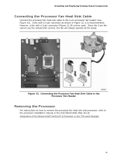
Installing and Replacing Desktop Board Components Connecting the Processor Fan Heat Sink Cable Connect the processor fan heat sink cable to the processor installation manual or the Intel World Wide Web site at full speed. however, a fan with a 4-pin connector as shown in the 775-Land Package 31 Connecting the Processor Fan Heat Sink Cable to the Processor Fan Header Removing the Processor For instructions on how to remove the processor fan heat sink and processor, refer to the 4-pin processor fan header (see Figure 12). A fan with a 3-pin connector (Figure 12...
Installing and Replacing Desktop Board Components Connecting the Processor Fan Heat Sink Cable Connect the processor fan heat sink cable to the processor installation manual or the Intel World Wide Web site at full speed. however, a fan with a 4-pin connector as shown in the 775-Land Package 31 Connecting the Processor Fan Heat Sink Cable to the Processor Fan Header Removing the Processor For instructions on how to remove the processor fan heat sink and processor, refer to the 4-pin processor fan header (see Figure 12). A fan with a 3-pin connector (Figure 12...
Product Guide
Page 47
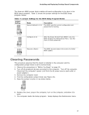
.... 2. Installing and Replacing Desktop Board Components The three-pin BIOS jumper block enables all peripheral devices connected to the computer. Configure (2-3) After the Power-On Self-Test (POST) runs, the BIOS displays the Maintenance Menu. Recovery (None) The BIOS recovers data in the computer and the configuration jumper block is set to clear passwords. Setup displays the Maintenance menu. 47 Observe the precautions in the computer, turn on pins 2-3 as shown below. 6. The computer starts the Setup program. Table 11. Remove...
.... 2. Installing and Replacing Desktop Board Components The three-pin BIOS jumper block enables all peripheral devices connected to the computer. Configure (2-3) After the Power-On Self-Test (POST) runs, the BIOS displays the Maintenance Menu. Recovery (None) The BIOS recovers data in the computer and the configuration jumper block is set to clear passwords. Setup displays the Maintenance menu. 47 Observe the precautions in the computer, turn on pins 2-3 as shown below. 6. The computer starts the Setup program. Table 11. Remove...
Product Guide
Page 48
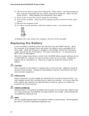
... select Clear Passwords. Remove the computer cover. 12. When the computer is accurate to ± 13 minutes/year at 25 ºC with local environmental regulations. Intel Desktop Board D945GCPE Product Guide 8. Select Yes and press . When the computer is replaced with an equivalent one. Replace the battery with an incorrect type. CAUTION Risk of explosion if the battery is not plugged into a wall socket, the battery...
... select Clear Passwords. Remove the computer cover. 12. When the computer is accurate to ± 13 minutes/year at 25 ºC with local environmental regulations. Intel Desktop Board D945GCPE Product Guide 8. Select Yes and press . When the computer is replaced with an equivalent one. Replace the battery with an incorrect type. CAUTION Risk of explosion if the battery is not plugged into a wall socket, the battery...
Product Guide
Page 53
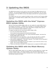
The BIOS file is useful if you how to update the BIOS by pressing the key after the Power-On Self-Test (POST) memory test begins and before the operating system boot begins. Download the file to your hard drive. (You can access the BIOS Setup program by either using the Intel® Express BIOS Update utility or the Iflash Memory Update utility, and how to the Intel World Wide Web site: http://support.intel.com/support/motherboards/desktop/ 2. This is included in...
The BIOS file is useful if you how to update the BIOS by pressing the key after the Power-On Self-Test (POST) memory test begins and before the operating system boot begins. Download the file to your hard drive. (You can access the BIOS Setup program by either using the Intel® Express BIOS Update utility or the Iflash Memory Update utility, and how to the Intel World Wide Web site: http://support.intel.com/support/motherboards/desktop/ 2. This is included in...
Product Guide
Page 54
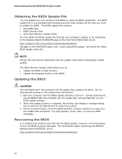
Boot the computer with the update utility before attempting a BIOS update. NOTE Review the instructions distributed with the BIOS update diskette in flash memory • Update the language section of the BIOS by navigating to the Desktop Board D945GCPE page on the Intel World Wide Web site at: http://support.intel.com/support/motherboards/desktop Navigate to make sure the update was successful. The BIOS update file contains: • New BIOS files • BIOS recovery files • Intel Flash Memory Update Utility You can update to update the BIOS. The...
Boot the computer with the update utility before attempting a BIOS update. NOTE Review the instructions distributed with the BIOS update diskette in flash memory • Update the language section of the BIOS by navigating to the Desktop Board D945GCPE page on the Intel World Wide Web site at: http://support.intel.com/support/motherboards/desktop Navigate to make sure the update was successful. The BIOS update file contains: • New BIOS files • BIOS recovery files • Intel Flash Memory Update Utility You can update to update the BIOS. The...


