
Product Specification
Page 5
... 9 1.2 Overview ...10 1.2.1 Feature Summary 10 1.2.2 Manufacturing Options 11 1.2.3 Board Layout 12 1.2.4 Block Diagram 14 1.3 Online Support ...15 1.4 Processor ...15 1.5 System Memory ...15 1.5.1 Memory Configurations 17 1.6 Intel® 915GV Chipset 21 1.6.1 Intel 915GV Graphics Subsystem 21 1.6.2 USB ...22 1.6.3 IDE Support 23 1.6.4 Real-Time Clock, CMOS SRAM, and Battery 24 1.7 PCI Express Connectors 24 1.8 I/O Controller...25 1.8.1 Serial...
... 9 1.2 Overview ...10 1.2.1 Feature Summary 10 1.2.2 Manufacturing Options 11 1.2.3 Board Layout 12 1.2.4 Block Diagram 14 1.3 Online Support ...15 1.4 Processor ...15 1.5 System Memory ...15 1.5.1 Memory Configurations 17 1.6 Intel® 915GV Chipset 21 1.6.1 Intel 915GV Graphics Subsystem 21 1.6.2 USB ...22 1.6.3 IDE Support 23 1.6.4 Real-Time Clock, CMOS SRAM, and Battery 24 1.7 PCI Express Connectors 24 1.8 I/O Controller...25 1.8.1 Serial...
Product Specification
Page 7
... Channel (Asymmetric) Mode Configuration with Three DIMMs 18 6. Thermal Monitoring ...30 13. Connection Diagram for IEEE 1394a Connector 54 20. Supported System Bus Frequency and Memory Speed Combinations 16 5. LAN Connector LED States 28 7. System Memory Map 41 11. Contents 4 Error ...18. Location of the Jumper Block 55 21. Board Dimensions...56 22. Processor Heatsink Airflow 60 24. Feature Summary ...10 2. Manufacturing Options 11 3. Board Components Shown in Figure 1 13 4. Supported Memory Configurations 16 6. Power States and Targeted System Power 33 9. Wake-...
... Channel (Asymmetric) Mode Configuration with Three DIMMs 18 6. Thermal Monitoring ...30 13. Connection Diagram for IEEE 1394a Connector 54 20. Supported System Bus Frequency and Memory Speed Combinations 16 5. LAN Connector LED States 28 7. System Memory Map 41 11. Contents 4 Error ...18. Location of the Jumper Block 55 21. Board Dimensions...56 22. Processor Heatsink Airflow 60 24. Feature Summary ...10 2. Manufacturing Options 11 3. Board Components Shown in Figure 1 13 4. Supported Memory Configurations 16 6. Power States and Targeted System Power 33 9. Wake-...
Product Specification
Page 9
... referred to as PCI is now called PCI Conventional. 9 1 Product Description What This Chapter Contains 1.1 PCI Bus Terminology Change 9 1.2 Overview ...10 1.3 Online Support ...15 1.4 Processor ...15 1.5 System Memory ...15 1.6 Intel® 915GV Chipset 21 1.7 PCI Express Connectors 24 1.8 I/O Controller...25 1.9 Audio Subsystem ...26 1.10 LAN Subsystem (Optional 28 1.11 Hardware Management Subsystem 29...
... referred to as PCI is now called PCI Conventional. 9 1 Product Description What This Chapter Contains 1.1 PCI Bus Terminology Change 9 1.2 Overview ...10 1.3 Online Support ...15 1.4 Processor ...15 1.5 System Memory ...15 1.6 Intel® 915GV Chipset 21 1.7 PCI Express Connectors 24 1.8 I/O Controller...25 1.9 Audio Subsystem ...26 1.10 LAN Subsystem (Optional 28 1.11 Hardware Management Subsystem 29...
Product Specification
Page 10
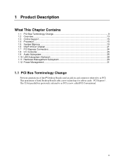
...D915GVWB. Intel Desktop Board D915GVWB Technical Product Specification 1.2 Overview 1.2.1 Feature Summary Table 1 summarizes the major features of : • Intel® 82915GV Graphics Memory Controller Hub (GMCH) • Intel® 82801FB I/O Controller Hub (ICH6) • 4 Mbit Firmware Hub (FWH) Intel® GMA900 onboard graphics subsystem Intel...USB Peripheral Interfaces LAN Support BIOS Instantly Available PC Technology microATX Form Factor (9.60 inches by 9.60 inches [243.84 millimeters by 243.84 millimeters]) Support for an Intel® Pentium® 4 processor in an LGA775 socket ...
...D915GVWB. Intel Desktop Board D915GVWB Technical Product Specification 1.2 Overview 1.2.1 Feature Summary Table 1 summarizes the major features of : • Intel® 82915GV Graphics Memory Controller Hub (GMCH) • Intel® 82801FB I/O Controller Hub (ICH6) • 4 Mbit Firmware Hub (FWH) Intel® GMA900 onboard graphics subsystem Intel...USB Peripheral Interfaces LAN Support BIOS Instantly Available PC Technology microATX Form Factor (9.60 inches by 9.60 inches [243.84 millimeters by 243.84 millimeters]) Support for an Intel® Pentium® 4 processor in an LGA775 socket ...
Product Specification
Page 15
... supply connectors Refer to support Intel Pentium 4 processors in an LGA775 processor socket with x16 organization are not supported. • 4 GB maximum total system memory. Use of supported system bus frequency and memory speed combinations. Supported processors for the D915GVWB board Refer to Table 4 on page 16 for a list of unsupported processors can damage the board, the processor, and the power...
... supply connectors Refer to support Intel Pentium 4 processors in an LGA775 processor socket with x16 organization are not supported. • 4 GB maximum total system memory. Use of supported system bus frequency and memory speed combinations. Supported processors for the D915GVWB board Refer to Table 4 on page 16 for a list of unsupported processors can damage the board, the processor, and the power...

Product Specification
Page 16
...39 for additional information on available memory. 16 Table 5 lists the supported DIMM configurations. DDR 400 800 MHz DDR 333 (Note) 800 or 533 MHz Note: When using an 800 MHz system bus frequency processor, DDR 333 memory is installed, the BIOS will attempt to accurately ...rows of SDRAM) and "SS" refers to install four 2048 MB (2 GB) modules for optimum performance. Refer to optimize system throughput. Intel Desktop Board D915GVWB Technical Product Specification • Non-ECC DIMMs • Serial Presence Detect • DDR 400 MHz and DDR 333 MHz SDRAM DIMMs Table ...
...39 for additional information on available memory. 16 Table 5 lists the supported DIMM configurations. DDR 400 800 MHz DDR 333 (Note) 800 or 533 MHz Note: When using an 800 MHz system bus frequency processor, DDR 333 memory is installed, the BIOS will attempt to accurately ...rows of SDRAM) and "SS" refers to install four 2048 MB (2 GB) modules for optimum performance. Refer to optimize system throughput. Intel Desktop Board D915GVWB Technical Product Specification • Non-ECC DIMMs • Serial Presence Detect • DDR 400 MHz and DDR 333 MHz SDRAM DIMMs Table ...

Product Specification
Page 23
... to one of the following modes: • Programmed I/O (PIO): processor controls data transfer. • 8237-style DMA: DMA offloads the processor, supporting transfer rates of up to 16 MB/sec. • Ultra DMA: DMA protocol on IDE bus supporting host and target throttling and transfer rates of up to 33 MB.../sec. • ATA-66: DMA protocol on IDE bus supporting host and target throttling and...
... to one of the following modes: • Programmed I/O (PIO): processor controls data transfer. • 8237-style DMA: DMA offloads the processor, supporting transfer rates of up to 16 MB/sec. • Ultra DMA: DMA protocol on IDE bus supporting host and target throttling and transfer rates of up to 33 MB.../sec. • ATA-66: DMA protocol on IDE bus supporting host and target throttling and...
Product Specification
Page 29
...11 Hardware Management Subsystem The hardware management features enable the board to boot from Intel's World Wide Web site. The Desktop Board has several hardware management features, including the following ASF support for PCI Express x1 bus add-in LAN cards and PCI Conventional bus add-...in LAN cards installed in PCI Conventional bus slot 2: • Monitoring of system firmware progress events, including: ⎯ BIOS present ⎯ Primary processor initialization ⎯ Memory ...
...11 Hardware Management Subsystem The hardware management features enable the board to boot from Intel's World Wide Web site. The Desktop Board has several hardware management features, including the following ASF support for PCI Express x1 bus add-in LAN cards and PCI Conventional bus add-...in LAN cards installed in PCI Conventional bus slot 2: • Monitoring of system firmware progress events, including: ⎯ BIOS present ⎯ Primary processor initialization ⎯ Memory ...
Product Specification
Page 31
...; Instantly Available PC technology ⎯ Resume on system configuration and environment. 1.11.5 Chassis Intrusion and Detection The board supports a chassis security feature that processor fan speed control remain enabled (default BIOS setting) when using Intel® Desktop Utilities, LANDesk* software, or thirdparty software. Disabling the chassis fan speed control results in the fan...
...; Instantly Available PC technology ⎯ Resume on system configuration and environment. 1.11.5 Chassis Intrusion and Detection The board supports a chassis security feature that processor fan speed control remain enabled (default BIOS setting) when using Intel® Desktop Utilities, LANDesk* software, or thirdparty software. Disabling the chassis fan speed control results in the fan...
Product Specification
Page 33
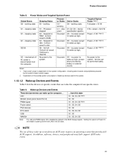
... sleeping state S4 - Context not saved. Notes: 1. Wake-up Devices and Events These devices/events can be performed safely. Processor stopped S3 - Soft off AC power is disabled by default in boards and peripherals powered by battery or external source. no ... Events Table 9 lists the devices or specific events that can wake the computer from an ACPI state requires an operating system that provides full ACPI support. Table 9. Product Description Table 8. Cold boot is dependent on the standby power consumption of these wake-up logic. 5 W < power < 52...
... sleeping state S4 - Context not saved. Notes: 1. Wake-up Devices and Events These devices/events can be performed safely. Processor stopped S3 - Soft off AC power is disabled by default in boards and peripherals powered by battery or external source. no ... Events Table 9 lists the devices or specific events that can wake the computer from an ACPI state requires an operating system that provides full ACPI support. Table 9. Product Description Table 8. Cold boot is dependent on the standby power consumption of these wake-up logic. 5 W < power < 52...

Product Specification
Page 35
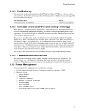
...For information about The location of the fan connectors The location of the fan connectors and sensors for thermal monitoring The signal names of the processor fan connector The signal names of the chassis fan connectors Refer to Figure 16, page 48 Figure 12, page 30 Table 20, page ... up of the computer through a network. Failure to a fan tachometer input of the hardware monitoring and fan control ASIC. • All fan connectors support closed-loop fan control that can damage the power supply. Upon detecting a Magic Packet* frame, the LAN subsystem asserts a wake-up signal that can...
...For information about The location of the fan connectors The location of the fan connectors and sensors for thermal monitoring The signal names of the processor fan connector The signal names of the chassis fan connectors Refer to Figure 16, page 48 Figure 12, page 30 Table 20, page ... up of the computer through a network. Failure to a fan tachometer input of the hardware monitoring and fan control ASIC. • All fan connectors support closed-loop fan control that can damage the power supply. Upon detecting a Magic Packet* frame, the LAN subsystem asserts a wake-up signal that can...

Product Specification
Page 50
... Ground 5 RXN 6 RXP 7 Ground 2.8.2.1 Power Supply Connectors The board has two power supply connectors: • Main power - Failure to the processor voltage regulator and must always be used on the rightmost pins of ATX12V power supplies with 2 x 10 connectors previously used...to do so will prevent the board from booting. 50 The board supports the use of the main power connector, leaving pins 11, 12, 23, and 24 unconnected. • ATX12V power - a 2 x 12 connector. Intel Desktop Board D915GVWB Technical Product Specification Table 19. When using a power supply with a...
... Ground 5 RXN 6 RXP 7 Ground 2.8.2.1 Power Supply Connectors The board has two power supply connectors: • Main power - Failure to the processor voltage regulator and must always be used on the rightmost pins of ATX12V power supplies with 2 x 10 connectors previously used...to do so will prevent the board from booting. 50 The board supports the use of the main power connector, leaving pins 11, 12, 23, and 24 unconnected. • ATX12V power - a 2 x 12 connector. Intel Desktop Board D915GVWB Technical Product Specification Table 19. When using a power supply with a...
Product Specification
Page 70
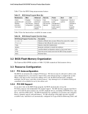
...onboard or add-in cards. BIOS Setup Program Menu Bar Maintenance Main Advanced Security Clears passwords and displays processor information Displays processor and memory configuration Configures advanced features available through the chipset Sets passwords and security features Power Boot Configures ... program, the BIOS automatically sets up to configure the system. Intel Desktop Board D915GVWB Technical Product Specification Table 37 lists the BIOS Setup program menu features. Table 38. The IDE interface supports hard drives up the PCI IDE connector with independent I /O ...
...onboard or add-in cards. BIOS Setup Program Menu Bar Maintenance Main Advanced Security Clears passwords and displays processor information Displays processor and memory configuration Configures advanced features available through the chipset Sets passwords and security features Power Boot Configures ... program, the BIOS automatically sets up to configure the system. Intel Desktop Board D915GVWB Technical Product Specification Table 37 lists the BIOS Setup program menu features. Table 38. The IDE interface supports hard drives up the PCI IDE connector with independent I /O ...
Product Specification
Page 71
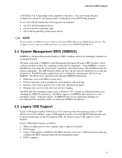
... Fixed-system data, such as peripherals, serial numbers, and asset tags • Resource data, such as memory size, cache size, and processor speed • Dynamic data, such as event detection and error logging Non-Plug and Play operating systems, such as third-party management software ...menu. 4. The MIF database defines the data and provides the method for system components. The main component of the drive. Legacy USB support is the Management Information Format (MIF) database, which contains information about the computing system and its components. You can obtain the system types...
... Fixed-system data, such as peripherals, serial numbers, and asset tags • Resource data, such as memory size, cache size, and processor speed • Dynamic data, such as event detection and error logging Non-Plug and Play operating systems, such as third-party management software ...menu. 4. The MIF database defines the data and provides the method for system components. The main component of the drive. Legacy USB support is the Management Information Format (MIF) database, which contains information about the computing system and its components. You can obtain the system types...
English Product Guide
Page 5
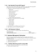
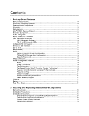
...Desktop Board Components 11 Processor ...13 Main Memory ...14 Intel® 915GV Express Chipset 14 Graphics Subsystem ...15 Audio Subsystem ...15 Input/Output (I/O) Controller 16 LAN Subsystem (Optional)...16 LAN Subsystem Software 16 RJ-45 LAN Connector LEDs 16 Hi-Speed USB 2.0 Support 17 Enhanced IDE Interface...19 Fan Connectors...19 Fan Speed Control (Intel® Precision Cooling Technology 19 Suspend to RAM (Instantly Available PC Technology 20 Resume on Ring ...21 Wake from USB ...21 Wake from PS/2 Keyboard/Mouse 21 PME# Wakeup Support 21 Speaker...21 Battery...21 Real-Time Clock...
...Desktop Board Components 11 Processor ...13 Main Memory ...14 Intel® 915GV Express Chipset 14 Graphics Subsystem ...15 Audio Subsystem ...15 Input/Output (I/O) Controller 16 LAN Subsystem (Optional)...16 LAN Subsystem Software 16 RJ-45 LAN Connector LEDs 16 Hi-Speed USB 2.0 Support 17 Enhanced IDE Interface...19 Fan Connectors...19 Fan Speed Control (Intel® Precision Cooling Technology 19 Suspend to RAM (Instantly Available PC Technology 20 Resume on Ring ...21 Wake from USB ...21 Wake from PS/2 Keyboard/Mouse 21 PME# Wakeup Support 21 Speaker...21 Battery...21 Real-Time Clock...
English Product Guide
Page 9
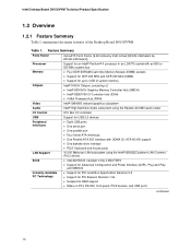
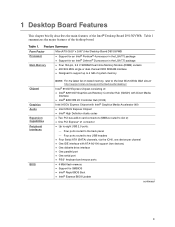
... describes the main features of the desktop board. Table 1. Feature Summary Form Factor MicroATX (9.60" x 9.60") Intel Desktop Board D915GVWB Processor • Support for an Intel® Pentium® 4 processor in the LGA775 package • Support for an Intel® Celeron® D processor in the LGA775 package Main Memory • Four 184-pin, 2.5 V SDRAM Dual Inline Memory Module (DIMM...
... describes the main features of the desktop board. Table 1. Feature Summary Form Factor MicroATX (9.60" x 9.60") Intel Desktop Board D915GVWB Processor • Support for an Intel® Pentium® 4 processor in the LGA775 package • Support for an Intel® Celeron® D processor in the LGA775 package Main Memory • Four 184-pin, 2.5 V SDRAM Dual Inline Memory Module (DIMM...
English Product Guide
Page 12
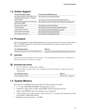
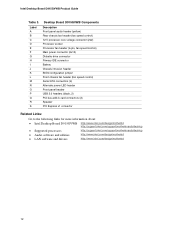
... (2) Speaker PCI Express x1 connector Related Links: Go to the following links for more information about: • Intel Desktop Board D915GVWB http://www.intel.com/design/motherbd http://support.intel.com/support/motherboards/desktop • Supported processors http://support.intel.com/support/motherboards/desktop • Audio software and utilities http://www.intel.com/design/motherbd • LAN software and drivers http://www...
... (2) Speaker PCI Express x1 connector Related Links: Go to the following links for more information about: • Intel Desktop Board D915GVWB http://www.intel.com/design/motherbd http://support.intel.com/support/motherboards/desktop • Supported processors http://support.intel.com/support/motherboards/desktop • Audio software and utilities http://www.intel.com/design/motherbd • LAN software and drivers http://www...
English Product Guide
Page 13
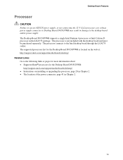
The supported processors list for the Desktop Board D915GVWB: http://support.intel.com/support/motherboards/desktop/ • Instructions on installing or upgrading the processor, page 28 in Chapter 2. • The location of the power connector, page 41 in Chapter 2. 13 Desktop Board Features Processor CAUTION Failure to use an ATX12V power supply, or not connecting the 12 V (2x2) processor core...
The supported processors list for the Desktop Board D915GVWB: http://support.intel.com/support/motherboards/desktop/ • Instructions on installing or upgrading the processor, page 28 in Chapter 2. • The location of the power connector, page 41 in Chapter 2. 13 Desktop Board Features Processor CAUTION Failure to use an ATX12V power supply, or not connecting the 12 V (2x2) processor core...

English Product Guide
Page 31
... not be controlled and will run at : http://support.intel.com/support/processors/pentium4/intnotes478.htm Connecting the Processor Fan Heat Sink Cable Connect the processor fan heat sink cable to the Processor Fan Connector 31 For instructions on how to attach the processor fan heat sink to the integrated processor fan heat sink RM, refer to the boxed...
... not be controlled and will run at : http://support.intel.com/support/processors/pentium4/intnotes478.htm Connecting the Processor Fan Heat Sink Cable Connect the processor fan heat sink cable to the Processor Fan Connector 31 For instructions on how to attach the processor fan heat sink to the integrated processor fan heat sink RM, refer to the boxed...

English Product Guide
Page 32
... MHz Channel A Channel B Figure 12. Intel Desktop Board D915GVWB Product Guide Removing the Processor For instruction on how to remove the processor fan heat sink and processor, refer to the processor installation manual or the Intel World Wide Web site at : http://www.intel.com/technology/memory/pcsdram/spec/ The desktop ...(black) in DIMM 0 (blue) of both Channel A and Channel B. You can access the PC Serial Presence Detect Specification at : http://support.intel.com/support/processors/pentium4/inuse.htm Installing and Removing Memory NOTE To be fully compliant with all applicable...
... MHz Channel A Channel B Figure 12. Intel Desktop Board D915GVWB Product Guide Removing the Processor For instruction on how to remove the processor fan heat sink and processor, refer to the processor installation manual or the Intel World Wide Web site at : http://www.intel.com/technology/memory/pcsdram/spec/ The desktop ...(black) in DIMM 0 (blue) of both Channel A and Channel B. You can access the PC Serial Presence Detect Specification at : http://support.intel.com/support/processors/pentium4/inuse.htm Installing and Removing Memory NOTE To be fully compliant with all applicable...


