
Product Specification
Page 5
...1.2.2 Manufacturing Options 11 1.2.3 Board Layout 12 1.2.4 Block Diagram 14 1.3 Online Support ...15 1.4 Processor ...15 1.5 System Memory ...15 1.5.1 Memory Configurations 17 1.6 Intel® 915GV Chipset 21 1.6.1 Intel 915GV Graphics Subsystem 21 1.6.2 USB ...22 1.6.3 IDE Support 23 1.6.4 Real-Time Clock, CMOS SRAM, and Battery 24... Monitoring and Fan Control ASIC 29 1.11.2 Thermal Monitoring 30 1.11.3 Fan Monitoring 31 1.11.4 Fan Speed Control (Intel® Precision Cooling Technology 31 1.11.5 Chassis Intrusion and Detection 31 1.12 Power Management ...31 1.12.1 ACPI ...32...
...1.2.2 Manufacturing Options 11 1.2.3 Board Layout 12 1.2.4 Block Diagram 14 1.3 Online Support ...15 1.4 Processor ...15 1.5 System Memory ...15 1.5.1 Memory Configurations 17 1.6 Intel® 915GV Chipset 21 1.6.1 Intel 915GV Graphics Subsystem 21 1.6.2 USB ...22 1.6.3 IDE Support 23 1.6.4 Real-Time Clock, CMOS SRAM, and Battery 24... Monitoring and Fan Control ASIC 29 1.11.2 Thermal Monitoring 30 1.11.3 Fan Monitoring 31 1.11.4 Fan Speed Control (Intel® Precision Cooling Technology 31 1.11.5 Chassis Intrusion and Detection 31 1.12 Power Management ...31 1.12.1 ACPI ...32...
Product Specification
Page 6
Intel Desktop Board D915GVWB Technical Product Specification 2.3 DMA Channels ...41 2.4 Fixed I/O Map...42 2.5 PCI Configuration Space Map 43 2.6 Interrupts ...44 2.7 PCI Conventional Interrupt Routing Map 45 2.8 ... of Conformity Statement 65 2.15.4 Product Ecology Statements 66 2.15.5 Product Certification Markings (Board Level 67 3 Overview of BIOS Features 3.1 Introduction ...69 3.2 BIOS Flash Memory Organization 70 3.3 Resource Configuration 70 3.3.1 PCI Autoconfiguration 70 3.3.2 PCI IDE Support 70 3.4 System Management BIOS (SMBIOS 71 3.5 Legacy USB Support...71 3.6 BIOS Updates ...
Intel Desktop Board D915GVWB Technical Product Specification 2.3 DMA Channels ...41 2.4 Fixed I/O Map...42 2.5 PCI Configuration Space Map 43 2.6 Interrupts ...44 2.7 PCI Conventional Interrupt Routing Map 45 2.8 ... of Conformity Statement 65 2.15.4 Product Ecology Statements 66 2.15.5 Product Certification Markings (Board Level 67 3 Overview of BIOS Features 3.1 Introduction ...69 3.2 BIOS Flash Memory Organization 70 3.3 Resource Configuration 70 3.3.1 PCI Autoconfiguration 70 3.3.2 PCI IDE Support 70 3.4 System Management BIOS (SMBIOS 71 3.5 Legacy USB Support...71 3.6 BIOS Updates ...
Product Specification
Page 7
...28 12. Location of the Standby Power Indicator LED 37 14. Processor Heatsink Airflow 60 24. Feature Summary ...10 2. Memory Channel Configuration 17 4. Dual Channel (Interleaved) Mode Configuration with Two DIMMs 18 5. Connection Diagram for High Definition Audio Subsystem......... 27 10. Board Components Shown in Figure 1 13 4. System Memory Map 41 11. Component-side Connectors 48 17. Block Diagram...14 3. Single Channel (Asymmetric) Mode Configuration with One DIMM 20 8. ...
...28 12. Location of the Standby Power Indicator LED 37 14. Processor Heatsink Airflow 60 24. Feature Summary ...10 2. Memory Channel Configuration 17 4. Dual Channel (Interleaved) Mode Configuration with Two DIMMs 18 5. Connection Diagram for High Definition Audio Subsystem......... 27 10. Board Components Shown in Figure 1 13 4. System Memory Map 41 11. Component-side Connectors 48 17. Block Diagram...14 3. Single Channel (Asymmetric) Mode Configuration with One DIMM 20 8. ...
Product Specification
Page 9
... an add-in cards: PCI Express*. 1 Product Description What This Chapter Contains 1.1 PCI Bus Terminology Change 9 1.2 Overview ...10 1.3 Online Support ...15 1.4 Processor ...15 1.5 System Memory ...15 1.6 Intel® 915GV Chipset 21 1.7 PCI Express Connectors 24 1.8 I/O Controller...25 1.9 Audio Subsystem ...26 1.10 LAN Subsystem (Optional 28 1.11 Hardware Management Subsystem 29 1.12 Power...
... an add-in cards: PCI Express*. 1 Product Description What This Chapter Contains 1.1 PCI Bus Terminology Change 9 1.2 Overview ...10 1.3 Online Support ...15 1.4 Processor ...15 1.5 System Memory ...15 1.6 Intel® 915GV Chipset 21 1.7 PCI Express Connectors 24 1.8 I/O Controller...25 1.9 Audio Subsystem ...26 1.10 LAN Subsystem (Optional 28 1.11 Hardware Management Subsystem 29 1.12 Power...
Product Specification
Page 10
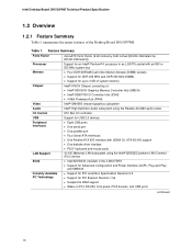
...; Intel/AMI BIOS (resident in the 4 Mbit FWH) • Support for Advanced Configuration and Power Interface (ACPI), Plug and Play, and SMBIOS • Support for PCI Local Bus Specification Revision 2.2 • Support for PCI Express Revision 1.0a • Suspend to 4 GB of system memory Intel® 915GV Chipset, consisting of the Desktop Board D915GVWB.
...; Intel/AMI BIOS (resident in the 4 Mbit FWH) • Support for Advanced Configuration and Power Interface (ACPI), Plug and Play, and SMBIOS • Support for PCI Local Bus Specification Revision 2.2 • Support for PCI Express Revision 1.0a • Suspend to 4 GB of system memory Intel® 915GV Chipset, consisting of the Desktop Board D915GVWB.
Product Specification
Page 14
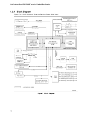
Block Diagram OM17320 14 Intel Desktop Board D915GVWB Technical Product Specification 1.2.4 Block Diagram Figure 2 is a block diagram of the major functional areas of the board. PCI Express x1 Slot 1 PCI Express...Drive Connector DMI Interconnect High Definition Audio Link LAN Connect Interface Intel 82915GV Graphics and Memory Controller Hub (GMCH) VGA Port Channel A DIMMs (2) Display Interface Dual-Channel Memory Bus SMBus Channel B DIMMs (2) Intel 82801FB I/O Controller Hub (ICH6) 4 Mbit Firmware Hub (FWH) Intel 915GV Chipset 10/100 LAN PLC LAN Connector IEEE-1394a Connectors ...
Block Diagram OM17320 14 Intel Desktop Board D915GVWB Technical Product Specification 1.2.4 Block Diagram Figure 2 is a block diagram of the major functional areas of the board. PCI Express x1 Slot 1 PCI Express...Drive Connector DMI Interconnect High Definition Audio Link LAN Connect Interface Intel 82915GV Graphics and Memory Controller Hub (GMCH) VGA Port Channel A DIMMs (2) Display Interface Dual-Channel Memory Bus SMBus Channel B DIMMs (2) Intel 82801FB I/O Controller Hub (ICH6) 4 Mbit Firmware Hub (FWH) Intel 915GV Chipset 10/100 LAN PLC LAN Connector IEEE-1394a Connectors ...
Product Specification
Page 15
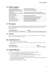
... Description 1.3 Online Support To find information about... Intel Desktop Board D915GVWB under "Desktop Board Products" or "Desktop Board Support" Available configurations for a list of addressable memory. • Minimum total system memory: 128 MB 15 See the Intel web site listed below for the most up-to... Table 4 on page 16 for the Desktop Board D915GVWB Processor data sheets ICH6 addressing Custom splash screens...
... Description 1.3 Online Support To find information about... Intel Desktop Board D915GVWB under "Desktop Board Products" or "Desktop Board Support" Available configurations for a list of addressable memory. • Minimum total system memory: 128 MB 15 See the Intel web site listed below for the most up-to... Table 4 on page 16 for the Desktop Board D915GVWB Processor data sheets ICH6 addressing Custom splash screens...

Product Specification
Page 16
... (Note) 800 or 533 MHz Note: When using an 800 MHz system bus frequency processor, DDR 333 memory is possible to Section 2.2.1, on available memory. 16 Table 5. Table 4. If non-SPD memory is available. Intel Desktop Board D915GVWB Technical Product Specification • Non-ECC DIMMs • Serial Presence Detect • DDR 400 MHz and DDR...
... (Note) 800 or 533 MHz Note: When using an 800 MHz system bus frequency processor, DDR 333 memory is possible to Section 2.2.1, on available memory. 16 Table 5. Table 4. If non-SPD memory is available. Intel Desktop Board D915GVWB Technical Product Specification • Non-ECC DIMMs • Serial Presence Detect • DDR 400 MHz and DDR...

Product Specification
Page 17
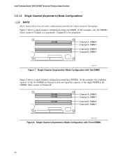
...can vary from one channel to the other but the installed memory capacity for each channel must be used . This mode is installed or the memory capacities are black. Memory Channel Configuration 17 If different speed DIMMs are blue. NOTE ...OM17321 Figure 3. If different speed DIMMs are equal. Product Description 1.5.1 Memory Configurations The Intel 82915GV GMCH supports two types of both channels are unequal. Figure 3 illustrates the memory channel and DIMM configuration. The DIMM1 sockets of memory organization: • Dual channel (Interleaved) mode. This mode is ...
...can vary from one channel to the other but the installed memory capacity for each channel must be used . This mode is installed or the memory capacities are black. Memory Channel Configuration 17 If different speed DIMMs are blue. NOTE ...OM17321 Figure 3. If different speed DIMMs are equal. Product Description 1.5.1 Memory Configurations The Intel 82915GV GMCH supports two types of both channels are unequal. Figure 3 illustrates the memory channel and DIMM configuration. The DIMM1 sockets of memory organization: • Dual channel (Interleaved) mode. This mode is ...
Product Specification
Page 20
... A is not populated. 256 MB Channel A, DIMM 0 Channel A, DIMM 1 Channel B, DIMM 0 Channel B, DIMM 1 OM17125 Figure 7. Intel Desktop Board D915GVWB Technical Product Specification 1.5.1.2 Single Channel (Asymmetric) Mode Configurations NOTE Dual channel (Interleaved) mode configurations provide the highest memory throughput. Figure 7 shows a single channel configuration using three DIMMs. In this example, only the DIMM0 (blue...
... A is not populated. 256 MB Channel A, DIMM 0 Channel A, DIMM 1 Channel B, DIMM 0 Channel B, DIMM 1 OM17125 Figure 7. Intel Desktop Board D915GVWB Technical Product Specification 1.5.1.2 Single Channel (Asymmetric) Mode Configurations NOTE Dual channel (Interleaved) mode configurations provide the highest memory throughput. Figure 7 shows a single channel configuration using three DIMMs. In this example, only the DIMM0 (blue...
Product Specification
Page 21
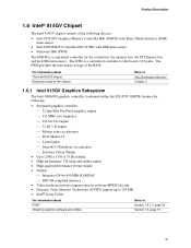
...) The GMCH is a centralized controller for the board's I/O paths. The ICH6 is a centralized controller for software MPEG2 decode • Dynamic Video Memory Technology (DVMT) support up to 224 MB • Intel® Zoom Utility For information about DVMT Obtaining graphics software and utilities Refer to Section 1.6.1.1, page 22 Section 1.3, page 15 21...
...) The GMCH is a centralized controller for the board's I/O paths. The ICH6 is a centralized controller for software MPEG2 decode • Dynamic Video Memory Technology (DVMT) support up to 224 MB • Intel® Zoom Utility For information about DVMT Obtaining graphics software and utilities Refer to Section 1.6.1.1, page 22 Section 1.3, page 15 21...
Product Specification
Page 22
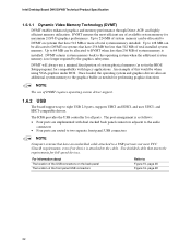
... front panel USB connectors NOTE Computer systems that meets the requirements for performing graphics functions. Intel Desktop Board D915GVWB Technical Product Specification 1.6.1.1 Dynamic Video Memory Technology (DVMT) DVMT enables enhanced graphics and memory performance through Direct AGP, and highly efficient memory utilization. DVMT ensures the most efficient use a minimal fixed portion of this would be...
... front panel USB connectors NOTE Computer systems that meets the requirements for performing graphics functions. Intel Desktop Board D915GVWB Technical Product Specification 1.6.1.1 Dynamic Video Memory Technology (DVMT) DVMT enables enhanced graphics and memory performance through Direct AGP, and highly efficient memory utilization. DVMT ensures the most efficient use a minimal fixed portion of this would be...
Product Specification
Page 24
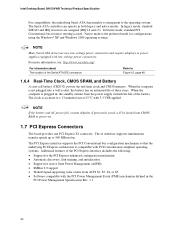
... 16, page 48 1.6.4 Real-Time Clock, CMOS SRAM, and Battery A coin-cell battery (CR2032) powers the real-time clock and CMOS memory. The x1 interface supports simultaneous transfer speeds up to the operating system. Native mode is not plugged into CMOS RAM at 25 ºC with...custom defaults, if previously saved, will be loaded into a wall socket, the battery has an estimated life of three years. Intel Desktop Board D915GVWB Technical Product Specification For compatibility, the underlying Serial ATA functionality is transparent to 500 MBytes/sec The PCI Express interface supports the PCI...
... 16, page 48 1.6.4 Real-Time Clock, CMOS SRAM, and Battery A coin-cell battery (CR2032) powers the real-time clock and CMOS memory. The x1 interface supports simultaneous transfer speeds up to the operating system. Native mode is not plugged into CMOS RAM at 25 ºC with...custom defaults, if previously saved, will be loaded into a wall socket, the battery has an estimated life of three years. Intel Desktop Board D915GVWB Technical Product Specification For compatibility, the underlying Serial ATA functionality is transparent to 500 MBytes/sec The PCI Express interface supports the PCI...
Product Specification
Page 29
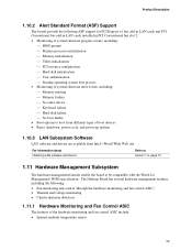
...• Monitoring of system firmware progress events, including: ⎯ BIOS present ⎯ Primary processor initialization ⎯ Memory initialization ⎯ Video initialization ⎯ PCI resource configuration ⎯ Hard-disk initialization ⎯ User authentication ⎯... Starting operating system boot process • Monitoring of system firmware error events, including: ⎯ Memory missing ⎯ Memory failure ⎯ No video device ⎯ Keyboard failure ⎯ Hard-disk failure ⎯ No boot ... enable the board to boot from Intel's World Wide Web site.
...• Monitoring of system firmware progress events, including: ⎯ BIOS present ⎯ Primary processor initialization ⎯ Memory initialization ⎯ Video initialization ⎯ PCI resource configuration ⎯ Hard-disk initialization ⎯ User authentication ⎯... Starting operating system boot process • Monitoring of system firmware error events, including: ⎯ Memory missing ⎯ Memory failure ⎯ No video device ⎯ Keyboard failure ⎯ Hard-disk failure ⎯ No boot ... enable the board to boot from Intel's World Wide Web site.

Product Specification
Page 39
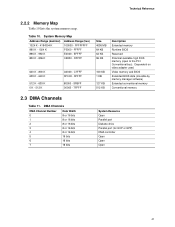
...respective section headings. 2.2 Memory Resources 2.2.1 Addressable Memory The board utilizes 4 GB of DRAM (total system memory). On a system that has 4 GB of system memory installed, it is not possible to use all of the installed memory due to 512 MB) • Memory-mapped I/O that is ...space being allocated for PCI Conventional bus add-in cards 39 2 Technical Reference What This Chapter Contains 2.1 Introduction ...39 2.2 Memory Resources ...39 2.3 DMA Channels ...41 2.4 Fixed I /O map, Table 13 defines the PCI Conventional bus configuration space map, and Table ...
...respective section headings. 2.2 Memory Resources 2.2.1 Addressable Memory The board utilizes 4 GB of DRAM (total system memory). On a system that has 4 GB of system memory installed, it is not possible to use all of the installed memory due to 512 MB) • Memory-mapped I/O that is ...space being allocated for PCI Conventional bus add-in cards 39 2 Technical Reference What This Chapter Contains 2.1 Introduction ...39 2.2 Memory Resources ...39 2.3 DMA Channels ...41 2.4 Fixed I /O map, Table 13 defines the PCI Conventional bus configuration space map, and Table ...

Product Specification
Page 40
... 09FFFFH 00000H Upper BIOS area (64 KB) Lower BIOS area (64 KB; 16 KB x 4) Add-in cards and BIOS settings. Intel Desktop Board D915GVWB Technical Product Specification The amount of installed memory that can be used when there is no overlap of system addresses. 4 GB Top of System Address Space FLASH APIC Reserved...
... 09FFFFH 00000H Upper BIOS area (64 KB) Lower BIOS area (64 KB; 16 KB x 4) Add-in cards and BIOS settings. Intel Desktop Board D915GVWB Technical Product Specification The amount of installed memory that can be used when there is no overlap of system addresses. 4 GB Top of System Address Space FLASH APIC Reserved...
Product Specification
Page 41
...- 9FBFF 00000 - 7FFFF Size 4095 MB 64 KB 64 KB 96 KB 160 KB 1 KB 127 KB 512 KB Description Extended memory Runtime BIOS Reserved Potential available high DOS memory (open to the PCI Conventional bus). DFFFF 640 K - 800 K 639 K - 640 K 512 K - 639 K 0 ...K - 512 K A0000 - FFFFF E0000 - Table 10. Video memory and BIOS Extended BIOS data (movable by memory manager software) Extended conventional memory Conventional memory 2.3 DMA Channels Table 11. System Memory Map Address Range (decimal) 1024 K - 4194304 K 960 K - 1024 K 896 K - 960 K 800 K - 896 ...
...- 9FBFF 00000 - 7FFFF Size 4095 MB 64 KB 64 KB 96 KB 160 KB 1 KB 127 KB 512 KB Description Extended memory Runtime BIOS Reserved Potential available high DOS memory (open to the PCI Conventional bus). DFFFF 640 K - 800 K 639 K - 640 K 512 K - 639 K 0 ...K - 512 K A0000 - FFFFF E0000 - Table 10. Video memory and BIOS Extended BIOS data (movable by memory manager software) Extended conventional memory Conventional memory 2.3 DMA Channels Table 11. System Memory Map Address Range (decimal) 1024 K - 4194304 K 960 K - 1024 K 896 K - 960 K 800 K - 896 ...

Product Specification
Page 43
...) 00 00 01 00 00 01 03 00 01 02 03 07 00 00 01 02 03 00 00 Description Memory controller of Intel 82915GV component Integrated graphics controller Integrated graphics controller Intel High Definition Audio Controller PCI Express port 1 (PCI Express x1 bus connector 1) PCI Express port 2 PCI Express port 4 (not used...
...) 00 00 01 00 00 01 03 00 01 02 03 07 00 00 01 02 03 00 00 Description Memory controller of Intel 82915GV component Integrated graphics controller Integrated graphics controller Intel High Definition Audio Controller PCI Express port 1 (PCI Express x1 bus connector 1) PCI Express port 2 PCI Express port 4 (not used...

Product Specification
Page 58
...A. 2.11.3 Fan Connector Current Capability CAUTION The processor fan must be connected to the processor fan connector, not to the processor, memory, and USB ports. Use the datasheets for each add-in cards. Fan Connector Current Capability Fan Connector Processor fan Front chassis fan... Rear chassis fan Maximum Available Current 1000 mA 600 mA 600 mA 58 Intel Desktop Board D915GVWB Technical Product Specification 2.11 Electrical Considerations 2.11.1 DC Loading Table 30 lists the DC loading characteristics of the fan ...
...A. 2.11.3 Fan Connector Current Capability CAUTION The processor fan must be connected to the processor fan connector, not to the processor, memory, and USB ports. Use the datasheets for each add-in cards. Fan Connector Current Capability Fan Connector Processor fan Front chassis fan... Rear chassis fan Maximum Available Current 1000 mA 600 mA 600 mA 58 Intel Desktop Board D915GVWB Technical Product Specification 2.11 Electrical Considerations 2.11.1 DC Loading Table 30 lists the DC loading characteristics of the fan ...

Product Specification
Page 69
... of BIOS and a revision code. The menu bar is accessed by pressing the key after the Power-On Self-Test (POST) memory test begins and before the operating system boot begins. The BIOS Setup program is shown below. When the BIOS Setup configuration jumper is...configure mode. The BIOS displays a message during POST identifying the type of BIOS Features What This Chapter Contains 3.1 Introduction ...69 3.2 BIOS Flash Memory Organization 70 3.3 Resource Configuration 70 3.4 System Management BIOS (SMBIOS 71 3.5 Legacy USB Support...71 3.6 BIOS Updates ...72 3.7 Boot Options ...73 3.8...
... of BIOS and a revision code. The menu bar is accessed by pressing the key after the Power-On Self-Test (POST) memory test begins and before the operating system boot begins. The BIOS Setup program is shown below. When the BIOS Setup configuration jumper is...configure mode. The BIOS displays a message during POST identifying the type of BIOS Features What This Chapter Contains 3.1 Introduction ...69 3.2 BIOS Flash Memory Organization 70 3.3 Resource Configuration 70 3.4 System Management BIOS (SMBIOS 71 3.5 Legacy USB Support...71 3.6 BIOS Updates ...72 3.7 Boot Options ...73 3.8...


