User Manual
Page 4
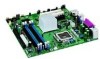
...048,576 bytes) Mbit Megabit (1,048,576 bits) MHz Megahertz (one million hertz) Box Contents • Intel Desktop Board • I/O shield • One IDE cable • Two SATA cables (second cable optional) • One diskette drive cable • One VGA port cover • ...and battery caution statement label • Intel® Express Installer CD-ROM • Trusted Platform Module Quick Reference (optional) • Trusted Platform Module Driver CD (optional) • Trusted Platform Warning Label (optional) iv Intel Desktop Board D915GEV/D915GUX/D915GAV/D915GAG Product Guide ...
...048,576 bytes) Mbit Megabit (1,048,576 bits) MHz Megahertz (one million hertz) Box Contents • Intel Desktop Board • I/O shield • One IDE cable • Two SATA cables (second cable optional) • One diskette drive cable • One VGA port cover • ...and battery caution statement label • Intel® Express Installer CD-ROM • Trusted Platform Module Quick Reference (optional) • Trusted Platform Module Driver CD (optional) • Trusted Platform Warning Label (optional) iv Intel Desktop Board D915GEV/D915GUX/D915GAV/D915GAG Product Guide ...
User Manual
Page 6
Intel Desktop Board D915GEV/D915GUX/D915GAV/D915GAG Product Guide Installing and Removing the Desktop Board 31 Installing and Removing a Processor 32 Installing a Processor 32 Installing the Processor Fan Heat Sink 34 Connecting the Processor Fan Heat Sink Cable 35 Removing ... x16 Card 41 Installing a PCI Express x16 Card 41 Removing the PCI Express x16 Card 41 Connecting the IDE Cable...42 Connecting the Serial ATA (SATA) Cable 43 Connecting Internal Headers 44 Installing a Front Panel Audio Solution 45 Connecting USB 2.0 Headers 46 Connecting the Front Panel Header 46 Setting Up ...
Intel Desktop Board D915GEV/D915GUX/D915GAV/D915GAG Product Guide Installing and Removing the Desktop Board 31 Installing and Removing a Processor 32 Installing a Processor 32 Installing the Processor Fan Heat Sink 34 Connecting the Processor Fan Heat Sink Cable 35 Removing ... x16 Card 41 Installing a PCI Express x16 Card 41 Removing the PCI Express x16 Card 41 Connecting the IDE Cable...42 Connecting the Serial ATA (SATA) Cable 43 Connecting Internal Headers 44 Installing a Front Panel Audio Solution 45 Connecting USB 2.0 Headers 46 Connecting the Front Panel Header 46 Setting Up ...
User Manual
Page 10
...⎯ Four ports routed to the back panel ⎯ Four ports routed to two USB headers • Four Serial ATA (SATA) channels, via the ICH6, one device per channel • One IDE interface with ATA-66/100 support (two devices) &#... Trusted Platform Module (Optional) Related Links: For more information about Intel Desktop Board D915GEV/D915GUX/D915GAV/D915GAG, including the Technical Product Specification (TPS), BIOS updates, and device drivers, go to: http://support.intel.com/support/motherboards/desktop/ 10 Intel Desktop Board D915GEV/D915GUX/D915GAV/D915GAG Product Guide Table 1.
...⎯ Four ports routed to the back panel ⎯ Four ports routed to two USB headers • Four Serial ATA (SATA) channels, via the ICH6, one device per channel • One IDE interface with ATA-66/100 support (two devices) &#... Trusted Platform Module (Optional) Related Links: For more information about Intel Desktop Board D915GEV/D915GUX/D915GAV/D915GAG, including the Technical Product Specification (TPS), BIOS updates, and device drivers, go to: http://support.intel.com/support/motherboards/desktop/ 10 Intel Desktop Board D915GEV/D915GUX/D915GAV/D915GAG Product Guide Table 1.

User Manual
Page 43
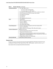
Either end of the cable can be connected to the connector (Figure 21, A) on the board. 3. Observe the precaution in "Before You Begin" on the board. Attach either cable end to the SATA drive or the connector on page 27. 2. A B Figure 21. For correct cable function: 1. Attach the other cable end to the desktop board. Installing and Replacing Desktop Board Components Connecting the Serial ATA (SATA) Cable The SATA cable (4-conductor) supports the Serial ATA protocol and connects a single drive to the drive (Figure 21, B). Connecting the Serial ATA Cable OM16897 43
Either end of the cable can be connected to the connector (Figure 21, A) on the board. 3. Observe the precaution in "Before You Begin" on the board. Attach either cable end to the SATA drive or the connector on page 27. 2. A B Figure 21. For correct cable function: 1. Attach the other cable end to the desktop board. Installing and Replacing Desktop Board Components Connecting the Serial ATA (SATA) Cable The SATA cable (4-conductor) supports the Serial ATA protocol and connects a single drive to the drive (Figure 21, B). Connecting the Serial ATA Cable OM16897 43


