User Manual
Page 5
... Manufacturing Options ...11 Supported Operating Systems 11 Desktop Board Components 12 Processor ...16 Main Memory ...17 Intel® 915G Express Chipset 18 Graphics Subsystem ...19 Audio Subsystem ...19 Input/Output (I/O) Controller 20 LAN Subsystem (Optional)...20 LAN Subsystem... Control (Intel® Precision Cooling Technology 24 Suspend to RAM (Instantly Available PC Technology 24 Resume on Ring ...25 Wake from USB ...26 Wake from PS/2 Keyboard/Mouse 26 PME# Wakeup Support 26 Speaker...26 Battery...26 Real-Time Clock...26 2 Installing and Replacing Desktop Board Components Before...
... Manufacturing Options ...11 Supported Operating Systems 11 Desktop Board Components 12 Processor ...16 Main Memory ...17 Intel® 915G Express Chipset 18 Graphics Subsystem ...19 Audio Subsystem ...19 Input/Output (I/O) Controller 20 LAN Subsystem (Optional)...20 LAN Subsystem... Control (Intel® Precision Cooling Technology 24 Suspend to RAM (Instantly Available PC Technology 24 Resume on Ring ...25 Wake from USB ...26 Wake from PS/2 Keyboard/Mouse 26 PME# Wakeup Support 26 Speaker...26 Battery...26 Real-Time Clock...26 2 Installing and Replacing Desktop Board Components Before...
User Manual
Page 6
Intel Desktop Board D915GEV/D915GUX/D915GAV/D915GAG Product Guide Installing and Removing the Desktop Board 31 Installing and Removing a Processor 32 Installing a Processor 32 Installing the Processor Fan Heat Sink 34 Connecting the Processor Fan Heat Sink Cable 35 Removing the Processor 35 Installing and Removing Memory 36 ... Back Panel Connectors...54 Replacing the Battery...55 3 BIOS Updating the BIOS with the Intel® Express BIOS Update Utility 59 Updating the BIOS with the Iflash Memory Update Utility 60 Obtaining the BIOS Update File 60 Updating the BIOS ...60 Recovering the...
Intel Desktop Board D915GEV/D915GUX/D915GAV/D915GAG Product Guide Installing and Removing the Desktop Board 31 Installing and Removing a Processor 32 Installing a Processor 32 Installing the Processor Fan Heat Sink 34 Connecting the Processor Fan Heat Sink Cable 35 Removing the Processor 35 Installing and Removing Memory 36 ... Back Panel Connectors...54 Replacing the Battery...55 3 BIOS Updating the BIOS with the Intel® Express BIOS Update Utility 59 Updating the BIOS with the Iflash Memory Update Utility 60 Obtaining the BIOS Update File 60 Updating the BIOS ...60 Recovering the...
User Manual
Page 7
...Desktop Boards D915GAV and D915GEV 51 28. Desktop Boards D915GEV and D915GAV Mounting Screw Hole Locations 31 7. Remove the Protective Socket Cover 33 10. Connecting the Processor Fan Heat Sink Cable to the Processor Fan Connector ........ 35 14. Connecting 2x10 Power Supply Cables 49 26. Contents 5 Desktop Board Resources Memory...the Correct DIMM 38 18. Connecting the IDE Cable 42 21. Connecting 2x12 Power Supply Cables 50 27. Intel Desktop Boards D915GUX and D915GAG Components 14 3. Back Panel LAN Connector LED Locations 20 4. Location of the BIOS Configuration ...
...Desktop Boards D915GAV and D915GEV 51 28. Desktop Boards D915GEV and D915GAV Mounting Screw Hole Locations 31 7. Remove the Protective Socket Cover 33 10. Connecting the Processor Fan Heat Sink Cable to the Processor Fan Connector ........ 35 14. Connecting 2x10 Power Supply Cables 49 26. Contents 5 Desktop Board Resources Memory...the Correct DIMM 38 18. Connecting the IDE Cable 42 21. Connecting 2x12 Power Supply Cables 50 27. Intel Desktop Boards D915GUX and D915GAG Components 14 3. Back Panel LAN Connector LED Locations 20 4. Location of the BIOS Configuration ...
User Manual
Page 8
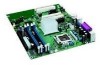
Manufacturing Options 11 3. Desktop Boards D915GAV and D915GEV Components 13 4. Desktop Board D915GEV/D915GUX Memory Configurations 18 7. RJ-45 10/100 Ethernet LAN Connector LEDs 21 8. Jumper Settings for the BIOS Setup Program Modes 52 13. BIOS Error Messages...74 18. Intel Desktop Board D915GEV/D915GUX/D915GAV/D915GAG Product Guide Tables 1. Feature Summary...9 2. Front Panel Audio Header Signal Names 45 10. USB...
Manufacturing Options 11 3. Desktop Boards D915GAV and D915GEV Components 13 4. Desktop Board D915GEV/D915GUX Memory Configurations 18 7. RJ-45 10/100 Ethernet LAN Connector LEDs 21 8. Jumper Settings for the BIOS Setup Program Modes 52 13. BIOS Error Messages...74 18. Intel Desktop Board D915GEV/D915GUX/D915GAV/D915GAG Product Guide Tables 1. Feature Summary...9 2. Front Panel Audio Header Signal Names 45 10. USB...
User Manual
Page 9
... Form Factor Processor Main Memory Chipset Graphics Audio Expansion Capabilities • ATX (12.00" x 9.60") Intel Desktop Board D915GAV/D915GEV • MicroATX (9.60" x 9.60") Intel Desktop Board D915GUX/D915GAG Support for an Intel® Pentium® 4 processor in card connectors (SMBus routed to 4 GB of the desktop board. 1 Desktop Board Features This chapter briefly describes the main features of Intel® Desktop Board D915GEV/D915GUX/ D915GAV/D915GAG.
... Form Factor Processor Main Memory Chipset Graphics Audio Expansion Capabilities • ATX (12.00" x 9.60") Intel Desktop Board D915GAV/D915GEV • MicroATX (9.60" x 9.60") Intel Desktop Board D915GUX/D915GAG Support for an Intel® Pentium® 4 processor in card connectors (SMBus routed to 4 GB of the desktop board. 1 Desktop Board Features This chapter briefly describes the main features of Intel® Desktop Board D915GEV/D915GUX/ D915GAV/D915GAG.
User Manual
Page 10
... One serial port • PS/2* keyboard and mouse ports BIOS • Intel/AMI BIOS • 4 Mbit symmetrical flash memory • Support for SMBIOS • Intel® Rapid BIOS Boot • Intel® Express BIOS Update Power Management • Support for Advanced Configuration and ...Security (Optional) Trusted Platform Module (Optional) Related Links: For more information about Intel Desktop Board D915GEV/D915GUX/D915GAV/D915GAG, including the Technical Product Specification (TPS), BIOS updates, and device drivers, go to: http://support.intel.com/support/motherboards/desktop/ 10
... One serial port • PS/2* keyboard and mouse ports BIOS • Intel/AMI BIOS • 4 Mbit symmetrical flash memory • Support for SMBIOS • Intel® Rapid BIOS Boot • Intel® Express BIOS Update Power Management • Support for Advanced Configuration and ...Security (Optional) Trusted Platform Module (Optional) Related Links: For more information about Intel Desktop Board D915GEV/D915GUX/D915GAV/D915GAG, including the Technical Product Specification (TPS), BIOS updates, and device drivers, go to: http://support.intel.com/support/motherboards/desktop/ 10
User Manual
Page 17
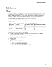
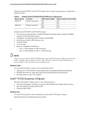
Desktop Board Features Main Memory NOTE To be fully compliant with all applicable Intel® SDRAM memory specifications, the board should be populated with gold-plated contacts • Unbuffered, non-registered single or double-sided DIMMs • Serial Presence Detect (SPD) memory only • Non-ECC RAM • 2.5 V memory • Memory configuration listed below: ⎯ Up to 1.0 GB utilizing 128...
Desktop Board Features Main Memory NOTE To be fully compliant with all applicable Intel® SDRAM memory specifications, the board should be populated with gold-plated contacts • Unbuffered, non-registered single or double-sided DIMMs • Serial Presence Detect (SPD) memory only • Non-ECC RAM • 2.5 V memory • Memory configuration listed below: ⎯ Up to 1.0 GB utilizing 128...
User Manual
Page 18
... operating system and applications. Intel Desktop Board D915GEV/D915GUX/D915GAV/D915GAG Product Guide Desktop boards D915GEV and D915GUX support dual or single channel memory configurations defined in Chapter 2 Intel® 915G Express Chipset The Intel 915G Express Chipset consists of tested memory, http://support.intel.com/support/motherboards/desktop/ • SDRAM specifications, http://www.intel.com/technology/memory/pcsdram/spec/ • Installing memory, page 36 in Table...
... operating system and applications. Intel Desktop Board D915GEV/D915GUX/D915GAV/D915GAG Product Guide Desktop boards D915GEV and D915GUX support dual or single channel memory configurations defined in Chapter 2 Intel® 915G Express Chipset The Intel 915G Express Chipset consists of tested memory, http://support.intel.com/support/motherboards/desktop/ • SDRAM specifications, http://www.intel.com/technology/memory/pcsdram/spec/ • Installing memory, page 36 in Table...
User Manual
Page 24
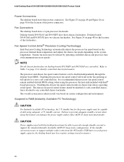
System fan noise may lose register settings stored in memory. 24 Refer to Table 3 on page 48 for the location of the fan headers. Disabling the chassis fan speed control results in ...standby line for the location of delivering adequate +5 V standby current. Suspend to identify controlled chassis fan headers. Intel Desktop Board D915GEV/D915GUX/D915GAV/D915GAG Product Guide Power Connectors The desktop boards have three chassis fan headers. Desktop boards D915GAV and D915GEV have three power connectors. It is attached to support multiple wake events from the PCI and/or USB...
System fan noise may lose register settings stored in memory. 24 Refer to Table 3 on page 48 for the location of the fan headers. Disabling the chassis fan speed control results in ...standby line for the location of delivering adequate +5 V standby current. Suspend to identify controlled chassis fan headers. Intel Desktop Board D915GEV/D915GUX/D915GAV/D915GAG Product Guide Power Connectors The desktop boards have three chassis fan headers. Desktop boards D915GAV and D915GEV have three power connectors. It is attached to support multiple wake events from the PCI and/or USB...
User Manual
Page 25
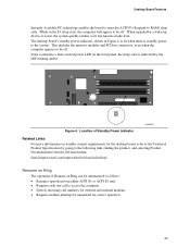
... 4. This includes the memory modules and PCI bus connectors, even when the computer appears to -RAM) sleep state. Desktop Board Features Instantly Available PC technology enables the board to enter the ACPI S3 (Suspend-to be off . The desktop board's standby power indicator, ... Resumes operation from the left-hand menu: http://support.intel.com/support/motherboards/desktop/ Resume on Ring The operation of Standby Power Indicator OM16879 Related Links: For more information on standby current requirements for the desktop board, refer to the Technical Product Specification by a wake...
... 4. This includes the memory modules and PCI bus connectors, even when the computer appears to -RAM) sleep state. Desktop Board Features Instantly Available PC technology enables the board to enter the ACPI S3 (Suspend-to be off . The desktop board's standby power indicator, ... Resumes operation from the left-hand menu: http://support.intel.com/support/motherboards/desktop/ Resume on Ring The operation of Standby Power Indicator OM16879 Related Links: For more information on standby current requirements for the desktop board, refer to the Technical Product Specification by a wake...
User Manual
Page 27
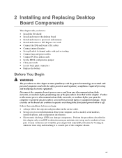
... links, networks, or modems before you how to: • Install the I/O shield • Install and remove the desktop board • Install and remove a processor and memory • Install and remove a PCI Express x16 card • Connect the IDE and Serial ATA cables • Connect...ESD) can damage components. Follow these guidelines before performing any procedures can result in personal injury or equipment damage. 2 Installing and Replacing Desktop Board Components This chapter tells you begin: • Always follow the steps in each procedure in the correct order. • Set up...
... links, networks, or modems before you how to: • Install the I/O shield • Install and remove the desktop board • Install and remove a processor and memory • Install and remove a PCI Express x16 card • Connect the IDE and Serial ATA cables • Connect...ESD) can damage components. Follow these guidelines before performing any procedures can result in personal injury or equipment damage. 2 Installing and Replacing Desktop Board Components This chapter tells you begin: • Always follow the steps in each procedure in the correct order. • Set up...

User Manual
Page 36
Dual Configuration Example 1 DIMM 0 DIMM 1 DIMM 0 DIMM 1 36 Intel Desktop Board D915GEV/D915GUX/D915GAV/D915GAG Product Guide Installing and Removing Memory NOTE To be fully compliant with all applicable Intel SDRAM memory specifications, the boards require DIMMs that support the Serial Presence Detect (SPD) data structure. Two or Four DIMMs Install a matched pair of DIMMs equal in speed and...
Dual Configuration Example 1 DIMM 0 DIMM 1 DIMM 0 DIMM 1 36 Intel Desktop Board D915GEV/D915GUX/D915GAV/D915GAG Product Guide Installing and Removing Memory NOTE To be fully compliant with all applicable Intel SDRAM memory specifications, the boards require DIMMs that support the Serial Presence Detect (SPD) data structure. Two or Four DIMMs Install a matched pair of DIMMs equal in speed and...

User Manual
Page 37
Dual Configuration Example 3 DIMM 0 DIMM 1 DIMM 0 DIMM 1 NOTE All other memory configurations will result in DIMM 0 (blue) and DIMM 1 (black) of channel A. Install a DIMM equal in speed and total size of the DIMMs installed in channel A ... 0 DIMM 1 Figure 15. Dual Configuration Example 2 Three DIMMs Install a matched pair of DIMMs equal in speed and size in single channel memory operation. 37 Installing and Replacing Desktop Board Components If additional memory is to be used, install another matched pair of DIMMs in DIMM 1 (black) in both channels A and B (see Figure 16). 256...
Dual Configuration Example 3 DIMM 0 DIMM 1 DIMM 0 DIMM 1 NOTE All other memory configurations will result in DIMM 0 (blue) and DIMM 1 (black) of channel A. Install a DIMM equal in speed and total size of the DIMMs installed in channel A ... 0 DIMM 1 Figure 15. Dual Configuration Example 2 Three DIMMs Install a matched pair of DIMMs equal in speed and size in single channel memory operation. 37 Installing and Replacing Desktop Board Components If additional memory is to be used, install another matched pair of DIMMs in DIMM 1 (black) in both channels A and B (see Figure 16). 256...

User Manual
Page 38
Matching the Correct DIMM 38 To make sure you have the correct DIMM, place the DIMM on the illustration in the DIMM sockets prior to installing the PCI Express video card to avoid interference with the memory retention mechanism. Intel Desktop Board D915GEV/D915GUX/D915GAV/D915GAG Product Guide Installing DIMMs CAUTION Install memory in Figure 17. DDR DDR2 mm 1 2 3 4 5 6 7 8 9 10 11 12 13 OM16847 Figure 17.
Matching the Correct DIMM 38 To make sure you have the correct DIMM, place the DIMM on the illustration in the DIMM sockets prior to installing the PCI Express video card to avoid interference with the memory retention mechanism. Intel Desktop Board D915GEV/D915GUX/D915GAV/D915GAG Product Guide Installing DIMMs CAUTION Install memory in Figure 17. DDR DDR2 mm 1 2 3 4 5 6 7 8 9 10 11 12 13 OM16847 Figure 17.
User Manual
Page 55
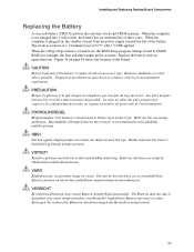
... one. VARO Räjähdysvaara, jos pariston tyyppi on page 58 shows the location of used batteries must be recycled where possible. Installing and Replacing Desktop Board Components Replacing the Battery A coin-cell battery (CR2032) powers the real-time clock and CMOS...
... one. VARO Räjähdysvaara, jos pariston tyyppi on page 58 shows the location of used batteries must be recycled where possible. Installing and Replacing Desktop Board Components Replacing the Battery A coin-cell battery (CR2032) powers the real-time clock and CMOS...

User Manual
Page 59
This chapter tells you can update the system BIOS while in the Windows environment. Updating the BIOS with the Intel Express BIOS Update utility: 1. Go to the D915GEV/D915GUX/D915GAV/D915GAG page, click "[view] Latest BIOS updates," and select the Express BIOS Update utility file. 3. Download... are updating the BIOS for the computer. Navigate to the Intel World Wide Web site: http://support.intel.com/support/motherboards/desktop/ 2. This step is accessed by either using the Intel Express BIOS Update utility or the Iflash Memory Update utility, and how to your hard drive where it was...
This chapter tells you can update the system BIOS while in the Windows environment. Updating the BIOS with the Intel Express BIOS Update utility: 1. Go to the D915GEV/D915GUX/D915GAV/D915GAG page, click "[view] Latest BIOS updates," and select the Express BIOS Update utility file. 3. Download... are updating the BIOS for the computer. Navigate to the Intel World Wide Web site: http://support.intel.com/support/motherboards/desktop/ 2. This step is accessed by either using the Intel Express BIOS Update utility or the Iflash Memory Update utility, and how to your hard drive where it was...
User Manual
Page 60
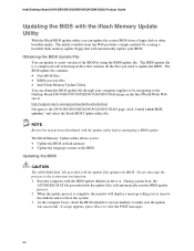
...the BIOS update diskette in flash memory • Update the language section of the BIOS by navigating to the Desktop Board D915GEV/D915GUX/D915GAV/D915GAG page on the Intel World Wide Web site at: http://support.intel.com/support/motherboards/desktop Navigate to the D915GEV/D915GUX/D915GAV/D915GAG page, click ... that will automatically update your computer supplier or by using the BIOS update file. Intel Desktop Board D915GEV/D915GUX/D915GAV/D915GAG Product Guide Updating the BIOS with the Iflash Memory Update Utility With the Iflash BIOS update utility you can update the system BIOS from...
...the BIOS update diskette in flash memory • Update the language section of the BIOS by navigating to the Desktop Board D915GEV/D915GUX/D915GAV/D915GAG page on the Intel World Wide Web site at: http://support.intel.com/support/motherboards/desktop Navigate to the D915GEV/D915GUX/D915GAV/D915GAG page, click ... that will automatically update your computer supplier or by using the BIOS update file. Intel Desktop Board D915GEV/D915GUX/D915GAV/D915GAG Product Guide Updating the BIOS with the Iflash Memory Update Utility With the Iflash BIOS update utility you can update the system BIOS from...

User Manual
Page 71
5 Desktop Board Resources Memory Map Table 13. System Memory Map Address Range (decimal) Address Range (hex) 1024 K - 4194304 K 100000 - DFFFF 640 K - 800 K 639 K - 640 K A0000 - EFFFF 800 K - 896 K C8000 - FFFFFFFF 960 K - 1024 K ... 64 KB 96 KB 160 KB 1 KB 127 KB 512 KB Description Extended Memory Runtime BIOS Reserved Available high DOS memory (open to the PCI bus) Video memory and BIOS Extended BIOS data (movable by memory manager software) Extended conventional memory Conventional memory DMA Channels Table 14. DMA Channels DMA Channel Number 0 1 2 3 4 5 6 7 Data ...
5 Desktop Board Resources Memory Map Table 13. System Memory Map Address Range (decimal) Address Range (hex) 1024 K - 4194304 K 100000 - DFFFF 640 K - 800 K 639 K - 640 K A0000 - EFFFF 800 K - 896 K C8000 - FFFFFFFF 960 K - 1024 K ... 64 KB 96 KB 160 KB 1 KB 127 KB 512 KB Description Extended Memory Runtime BIOS Reserved Available high DOS memory (open to the PCI bus) Video memory and BIOS Extended BIOS data (movable by memory manager software) Extended conventional memory Conventional memory DMA Channels Table 14. DMA Channels DMA Channel Number 0 1 2 3 4 5 6 7 Data ...
User Manual
Page 73
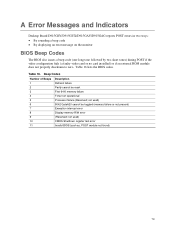
... used ) 8042 GateA20 cannot be reset First 64 K memory failure Timer not operational Processor failure (Reserved; not used ) CMOS Shutdown register test error Invalid BIOS (such as, POST module not found) 73 A Error Messages and Indicators Desktop Board D915GEV/D915GUX/D915GAV/D915GAG reports POST errors in two ways: •...properly checksum to zero. Beep Codes Number of Beeps 1 2 3 4 5 6 7 8 9 10 11 Description Refresh failure Parity cannot be toggled (memory failure or not present) Exception interrupt error Display memory R/W error (Reserved; Table 16 lists the BIOS codes.
... used ) 8042 GateA20 cannot be reset First 64 K memory failure Timer not operational Processor failure (Reserved; not used ) CMOS Shutdown register test error Invalid BIOS (such as, POST module not found) 73 A Error Messages and Indicators Desktop Board D915GEV/D915GUX/D915GAV/D915GAG reports POST errors in two ways: •...properly checksum to zero. Beep Codes Number of Beeps 1 2 3 4 5 6 7 8 9 10 11 Description Refresh failure Parity cannot be toggled (memory failure or not present) Exception interrupt error Display memory R/W error (Reserved; Table 16 lists the BIOS codes.
User Manual
Page 74
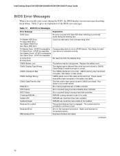
...the BIOS displays an error message describing the problem. Run Setup to reset values. Intel Desktop Board D915GEV/D915GUX/D915GAV/D915GAG Product Guide BIOS Error Messages When a recoverable error occurs during the memory test. BIOS Error Messages Error Message Explanation GA20 Error An error occurred with Gate-...when switching to make sure type is not an ATAPI device. These values have been corrupted. CMOS memory may be losing power. Table 17. Keyboard Error Error in the keyboard connection. KB/Interface Error Keyboard interface test failed.
...the BIOS displays an error message describing the problem. Run Setup to reset values. Intel Desktop Board D915GEV/D915GUX/D915GAV/D915GAG Product Guide BIOS Error Messages When a recoverable error occurs during the memory test. BIOS Error Messages Error Message Explanation GA20 Error An error occurred with Gate-...when switching to make sure type is not an ATAPI device. These values have been corrupted. CMOS memory may be losing power. Table 17. Keyboard Error Error in the keyboard connection. KB/Interface Error Keyboard interface test failed.


