
User Manual
Page 10
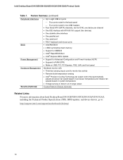
... • One serial port • PS/2* keyboard and mouse ports BIOS • Intel/AMI BIOS • 4 Mbit symmetrical flash memory • Support for SMBIOS • Intel® Rapid BIOS Boot • Intel® Express BIOS Update Power Management • Support for Advanced Configuration and Power Interface ...out of range values Security (Optional) Trusted Platform Module (Optional) Related Links: For more information about Intel Desktop Board D915GEV/D915GUX/D915GAV/D915GAG, including the Technical Product Specification (TPS), BIOS updates, and device drivers, go to: http://support...
... • One serial port • PS/2* keyboard and mouse ports BIOS • Intel/AMI BIOS • 4 Mbit symmetrical flash memory • Support for SMBIOS • Intel® Rapid BIOS Boot • Intel® Express BIOS Update Power Management • Support for Advanced Configuration and Power Interface ...out of range values Security (Optional) Trusted Platform Module (Optional) Related Links: For more information about Intel Desktop Board D915GEV/D915GUX/D915GAV/D915GAG, including the Technical Product Specification (TPS), BIOS updates, and device drivers, go to: http://support...

User Manual
Page 23
... Passwords The BIOS includes security features that detects if the chassis cover has been removed. If only the supervisor password is set , you can boot the computer. If only the supervisor password is set, pressing at several levels, including: • Advanced Configuration and Power Interface (ACPI) &#...viewing and changing depending on the desktop board. If both the supervisor and user passwords are set for the BIOS Setup and for booting the computer, with the desktop board requires an operating system that add-in card. Chassis Intrusion The board supports a chassis security...
... Passwords The BIOS includes security features that detects if the chassis cover has been removed. If only the supervisor password is set , you can boot the computer. If only the supervisor password is set, pressing at several levels, including: • Advanced Configuration and Power Interface (ACPI) &#...viewing and changing depending on the desktop board. If both the supervisor and user passwords are set for the BIOS Setup and for booting the computer, with the desktop board requires an operating system that add-in card. Chassis Intrusion The board supports a chassis security...

User Manual
Page 52
...jumper block enables all board configurations to clear passwords. Use this menu to be done in BIOS Setup. Table 12 shows the jumper settings for booting. 1 3 1 3 Configure (2-3) Recovery (None) After the Power-On Self-Test (POST) runs, the BIOS displays the Maintenance Menu. ...1 3 Mode Normal (default) (1-2) Description The BIOS uses the current configuration and passwords for the Setup program modes. Intel Desktop Board D915GEV/D915GUX/D915GAV/D915GAG Product Guide Setting the BIOS Configuration Jumper Block CAUTION Always turn off the power and unplug the power cord from a ...
...jumper block enables all board configurations to clear passwords. Use this menu to be done in BIOS Setup. Table 12 shows the jumper settings for booting. 1 3 1 3 Configure (2-3) Recovery (None) After the Power-On Self-Test (POST) runs, the BIOS displays the Maintenance Menu. ...1 3 Mode Normal (default) (1-2) Description The BIOS uses the current configuration and passwords for the Setup program modes. Intel Desktop Board D915GEV/D915GUX/D915GAV/D915GAG Product Guide Setting the BIOS Configuration Jumper Block CAUTION Always turn off the power and unplug the power cord from a ...

User Manual
Page 53
... power adapter). 3. Remove the computer cover. 12. To restore normal operation, place the jumper on the computer. 53 Turn off all peripheral devices connected to boot. 7. Replace the cover, plug in the computer, and turn on page 27. 2. Remove the computer cover. 4. Replace the cover, plug in the computer, turn on...
... power adapter). 3. Remove the computer cover. 12. To restore normal operation, place the jumper on the computer. 53 Turn off all peripheral devices connected to boot. 7. Replace the cover, plug in the computer, and turn on page 27. 2. Remove the computer cover. 4. Replace the cover, plug in the computer, turn on...

User Manual
Page 59
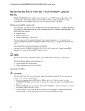
...on your hard drive. (You can also save this file to the D915GEV/D915GUX/D915GAV/D915GAG page, click "[view] Latest BIOS updates," and select the Express BIOS Update utility file. 3. Updating the BIOS with the Intel Express BIOS Update utility: 1. Download the file to your hard drive where it was ...you how to update the BIOS by pressing the key after the Power-On Self-Test (POST) memory test begins and before the operating system boot begins. This runs the update program. 6. Follow the instructions provided in the Windows environment. Your system will be used to recover the BIOS ...
...on your hard drive. (You can also save this file to the D915GEV/D915GUX/D915GAV/D915GAG page, click "[view] Latest BIOS updates," and select the Express BIOS Update utility file. 3. Updating the BIOS with the Intel Express BIOS Update utility: 1. Download the file to your hard drive where it was ...you how to update the BIOS by pressing the key after the Power-On Self-Test (POST) memory test begins and before the operating system boot begins. This runs the update program. 6. Follow the instructions provided in the Windows environment. Your system will be used to recover the BIOS ...
User Manual
Page 60
...can obtain the BIOS update file through your BIOS. Do not interrupt the process or the system may not function. 1. During system boot, the AUTOEXEC.BAT file provided with the Iflash Memory Update Utility With the Iflash BIOS update utility you to update the BIOS. When... a bootable flash memory update floppy that contains all the files you to remove the diskette and to reboot the system. 3. Intel Desktop Board D915GEV/D915GUX/D915GAV/D915GAG Product Guide Updating the BIOS with the update files will automatically run the BIOS update process. 2. The utility available from a...
...can obtain the BIOS update file through your BIOS. Do not interrupt the process or the system may not function. 1. During system boot, the AUTOEXEC.BAT file provided with the Iflash Memory Update Utility With the Iflash BIOS update utility you to update the BIOS. When... a bootable flash memory update floppy that contains all the files you to remove the diskette and to reboot the system. 3. Intel Desktop Board D915GEV/D915GUX/D915GAV/D915GAG Product Guide Updating the BIOS with the update files will automatically run the BIOS update process. 2. The utility available from a...
User Manual
Page 61
...LED. 1. On the jumper block, reinstall the jumper back on the computer, and allow it to show activity. Leave the update diskette in the boot block area, there is no video support. Turn off the computer, and disconnect its power cord. 9. Drive A activity will take a few ...minutes. 6. however, if an interruption occurs, the BIOS could be damaged. The recovery process will begin to boot. The following procedure uses recovery mode for more beeps indicating the successful recovery of the BIOS core. NOTE Because of the small amount of ...
...LED. 1. On the jumper block, reinstall the jumper back on the computer, and allow it to show activity. Leave the update diskette in the boot block area, there is no video support. Turn off the computer, and disconnect its power cord. 9. Drive A activity will take a few ...minutes. 6. however, if an interruption occurs, the BIOS could be damaged. The recovery process will begin to boot. The following procedure uses recovery mode for more beeps indicating the successful recovery of the BIOS core. NOTE Because of the small amount of ...
User Manual
Page 74
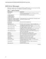
... Master HDD Error Sec Slave HDD Error Could not read /write test of the BIOS error messages. Pri Master Drive - Check Setup to boot. CMOS Date/Time Not Set The time and/or date values stored in the keyboard connection. Keyboard Is Locked The system keyboard lock is...be updated. Make sure keyboard is not an ATAPI device. Keyboard Error Error in CMOS are not the same as the last boot. Intel Desktop Board D915GEV/D915GUX/D915GAV/D915GAG Product Guide BIOS Error Messages When a recoverable error occurs during the POST, the BIOS displays an error message describing the problem...
... Master HDD Error Sec Slave HDD Error Could not read /write test of the BIOS error messages. Pri Master Drive - Check Setup to boot. CMOS Date/Time Not Set The time and/or date values stored in the keyboard connection. Keyboard Is Locked The system keyboard lock is...be updated. Make sure keyboard is not an ATAPI device. Keyboard Error Error in CMOS are not the same as the last boot. Intel Desktop Board D915GEV/D915GUX/D915GAV/D915GAG Product Guide BIOS Error Messages When a recoverable error occurs during the POST, the BIOS displays an error message describing the problem...

User Manual
Page 75
...On Board Parity Error Parity Error NVRAM / CMOS / PASSWORD cleared by Jumper Pressed Explanation Memory size has decreased since the last boot. Memory size has changed since the last boot. User must enter Setup. 75 This error is followed by an address. This error is followed by an address. If no... memory. CMOS is ignored and NVRAM is cleared. The system should be a problem with the system. Memory size has increased since the last boot. System did not find a device to boot. Error Messages and Indicators Table 43. If no memory was added, there may be bad.
...On Board Parity Error Parity Error NVRAM / CMOS / PASSWORD cleared by Jumper Pressed Explanation Memory size has decreased since the last boot. Memory size has changed since the last boot. User must enter Setup. 75 This error is followed by an address. This error is followed by an address. If no... memory. CMOS is ignored and NVRAM is cleared. The system should be a problem with the system. Memory size has increased since the last boot. System did not find a device to boot. Error Messages and Indicators Table 43. If no memory was added, there may be bad.

Product Specification
Page 7
... DIMMs 23 7. Memory Channel and DIMM Configuration 22 5. Dual Channel (Interleaved) Mode Configuration with Intel® Rapid BIOS Boot 96 3.8.1 Peripheral Selection and Configuration 96 3.8.2 Intel Rapid BIOS Boot 96 3.9 BIOS Security Features 97 4 Error Messages and Beep Codes 4.1 BIOS Error Messages 99 ... Configuration with Two DIMMs 23 6. Location of the Standby Power Indicator LED 47 17. D915GAV Board Dimensions 78 26. D915GAG Board Components 16 3. High Definition Audio Subsystem Block Diagram 34 12. Connection Diagram for IEEE 1394a Connectors 76 24. Connection...
... DIMMs 23 7. Memory Channel and DIMM Configuration 22 5. Dual Channel (Interleaved) Mode Configuration with Intel® Rapid BIOS Boot 96 3.8.1 Peripheral Selection and Configuration 96 3.8.2 Intel Rapid BIOS Boot 96 3.9 BIOS Security Features 97 4 Error Messages and Beep Codes 4.1 BIOS Error Messages 99 ... Configuration with Two DIMMs 23 6. Location of the Standby Power Indicator LED 47 17. D915GAV Board Dimensions 78 26. D915GAG Board Components 16 3. High Definition Audio Subsystem Block Diagram 34 12. Connection Diagram for IEEE 1394a Connectors 76 24. Connection...
Product Specification
Page 9
Contents 43. BIOS Setup Program Menu Bar 92 47. Boot Block Recovery Code Checkpoints 101 53. Boot Device Menu Options 95 49. Lower Nibble High Byte Functions 106 57. Beep Codes ...106 ix Supervisor and User Password Functions 97 50. Runtime Code ...
Contents 43. BIOS Setup Program Menu Bar 92 47. Boot Block Recovery Code Checkpoints 101 53. Boot Device Menu Options 95 49. Lower Nibble High Byte Functions 106 57. Beep Codes ...106 ix Supervisor and User Password Functions 97 50. Runtime Code ...

Product Specification
Page 29
... (such as a boot device by setting the BIOS Setup program's Boot menu to the operating system. hard disk drive) For information about The location of the Serial ATA IDE connectors on the D915GAV board The location of the Serial ATA IDE connectors on the D915GAG board Refer to ...drive reports the transfer rate and translation mode to reduce reflections, noise, and inductive coupling. An LS-120 drive can be installed on the D915GAG board Refer to device connections, unlike Parallel ATA IDE which supports a master/slave configuration and two devices per port. floppy disk drive) ...
... (such as a boot device by setting the BIOS Setup program's Boot menu to the operating system. hard disk drive) For information about The location of the Serial ATA IDE connectors on the D915GAV board The location of the Serial ATA IDE connectors on the D915GAG board Refer to ...drive reports the transfer rate and translation mode to reduce reflections, noise, and inductive coupling. An LS-120 drive can be installed on the D915GAG board Refer to device connections, unlike Parallel ATA IDE which supports a master/slave configuration and two devices per port. floppy disk drive) ...

Product Specification
Page 37
...Memory initialization ⎯ Video initialization ⎯ PCI resource configuration ⎯ Hard-disk initialization ⎯ User authentication ⎯ Starting operating system boot process • Monitoring of system firmware error events, including: ⎯ Memory missing ⎯ Memory failure ⎯ No video device &#...9135; Keyboard failure ⎯ Hard-disk failure ⎯ No boot media • Boot options to boot from different types of boot devices • Reset, shutdown, power cycle, and power up and the Gigabit LAN subsystem is powered...
...Memory initialization ⎯ Video initialization ⎯ PCI resource configuration ⎯ Hard-disk initialization ⎯ User authentication ⎯ Starting operating system boot process • Monitoring of system firmware error events, including: ⎯ Memory missing ⎯ Memory failure ⎯ No video device &#...9135; Keyboard failure ⎯ Hard-disk failure ⎯ No boot media • Boot options to boot from different types of boot devices • Reset, shutdown, power cycle, and power up and the Gigabit LAN subsystem is powered...

Product Specification
Page 43
working Device States D0 - working state Sleeping States S0 - Suspend to RAM. Soft off AC power is disconnected from the computer. Cold boot is dependent on the standby power consumption of the various system and power states. no power except for wake-up logic. 5 W < power < 52.5 W Power < 5 W (Note 2) ...
working Device States D0 - working state Sleeping States S0 - Suspend to RAM. Soft off AC power is disconnected from the computer. Cold boot is dependent on the standby power consumption of the various system and power states. no power except for wake-up logic. 5 W < power < 52.5 W Power < 5 W (Note 2) ...
Product Specification
Page 45
... location of the main power connector on the D915GAV board The location of the main power connector on the D915GAG board The signal names of the main power connector Refer to Figure 19, page 66 Figure 20, page ... about The location of the fan connectors on the D915GAV board The location of the fan connectors on the D915GAG board The location of the fan connectors and sensors for thermal monitoring on the D915GAV board The location of ... using the Last Power State feature in the BIOS Setup program's Boot menu. The method used depends on or off the system power through system control.
... location of the main power connector on the D915GAV board The location of the main power connector on the D915GAG board The signal names of the main power connector Refer to Figure 19, page 66 Figure 20, page ... about The location of the fan connectors on the D915GAV board The location of the fan connectors on the D915GAG board The location of the fan connectors and sensors for thermal monitoring on the D915GAV board The location of ... using the Last Power State feature in the BIOS Setup program's Boot menu. The method used depends on or off the system power through system control.

Product Specification
Page 72
... unconnected. • ATX12V power - a 2 x 12 connector. Failure to do so will be used on the rightmost pins of power from booting. • Alternate power - The 2 x 12 main power cable can provide up to avoid system instability: • The preferred method of ATX12V...directly to the board: ⎯ The main power connector ⎯ The ATX12V connector ⎯ The alternate power connector Table 31. Intel Desktop Board D915GAV/D915GAG Technical Product Specification 2.8.2.2 Power Supply Connectors The board has three power supply connectors: • Main power - a 2 x 2 ...
... unconnected. • ATX12V power - a 2 x 12 connector. Failure to do so will be used on the rightmost pins of power from booting. • Alternate power - The 2 x 12 main power cable can provide up to avoid system instability: • The preferred method of ATX12V...directly to the board: ⎯ The main power connector ⎯ The ATX12V connector ⎯ The alternate power connector Table 31. Intel Desktop Board D915GAV/D915GAG Technical Product Specification 2.8.2.2 Power Supply Connectors The board has three power supply connectors: • Main power - a 2 x 2 ...

Product Specification
Page 77
Technical Reference 2.9 Jumper Block CAUTION Do not move the jumper with the power on the D915GAG board.) The jumper block determines the BIOS Setup program's mode. Always turn off the power and unplug the power cord from the computer before changing a ... the POST runs, Setup runs automatically. Figure 24 shows the location of the Jumper Block OM16672 Table 38. Table 38 describes the jumper settings for booting. The 3 maintenance menu is required. 77
Technical Reference 2.9 Jumper Block CAUTION Do not move the jumper with the power on the D915GAG board.) The jumper block determines the BIOS Setup program's mode. Always turn off the power and unplug the power cord from the computer before changing a ... the POST runs, Setup runs automatically. Figure 24 shows the location of the Jumper Block OM16672 Table 38. Table 38 describes the jumper settings for booting. The 3 maintenance menu is required. 77
Product Specification
Page 91
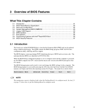
... the computer is accessed by pressing the key after the Power-On Self-Test (POST) memory test begins and before the operating system boot begins. The BIOS Setup program can be used to put the Desktop Board in configure mode. 91 The BIOS displays a message during...92 3.4 System Management BIOS (SMBIOS 93 3.5 Legacy USB Support...93 3.6 BIOS Updates ...94 3.7 Boot Options ...95 3.8 Fast Booting Systems with Intel® Rapid BIOS Boot 96 3.9 BIOS Security Features 97 3.1 Introduction The boards use an Intel/AMI BIOS that is stored in the Firmware Hub (FWH) and can be updated using a ...
... the computer is accessed by pressing the key after the Power-On Self-Test (POST) memory test begins and before the operating system boot begins. The BIOS Setup program can be used to put the Desktop Board in configure mode. 91 The BIOS displays a message during...92 3.4 System Management BIOS (SMBIOS 93 3.5 Legacy USB Support...93 3.6 BIOS Updates ...94 3.7 Boot Options ...95 3.8 Fast Booting Systems with Intel® Rapid BIOS Boot 96 3.9 BIOS Security Features 97 3.1 Introduction The boards use an Intel/AMI BIOS that is stored in the Firmware Hub (FWH) and can be updated using a ...
Product Specification
Page 92
...are automatically configured for use by the add-in card. 3.3.2 PCI IDE Support If you select Auto in cards. Intel Desktop Board D915GAV/D915GAG Technical Product Specification Table 46 lists the BIOS Setup program menu features. BIOS Setup Program Menu Bar Maintenance Main Advanced Security... processor and memory configuration Configures advanced features available through the chipset Sets passwords and security features Power Boot Configures power management features and power supply controls Selects boot options Exit Saves or discards changes to configure the system.
...are automatically configured for use by the add-in card. 3.3.2 PCI IDE Support If you select Auto in cards. Intel Desktop Board D915GAV/D915GAG Technical Product Specification Table 46 lists the BIOS Setup program menu features. BIOS Setup Program Menu Bar Maintenance Main Advanced Security... processor and memory configuration Configures advanced features available through the chipset Sets passwords and security features Power Boot Configures power management features and power supply controls Selects boot options Exit Saves or discards changes to configure the system.
Product Specification
Page 94
... either of the following utilities, which are available on the Intel World Wide Web site: • Intel® Express BIOS Update utility, which requires creation of a boot diskette and manual rebooting of the system. For information about The Intel World Wide Web site Refer to prevent accidentally installing an incompatible.... After the operating system loads the USB drivers, all legacy and non-legacy USB devices are available in the BIOS Setup program.) 6. Intel Desktop Board D915GAV/D915GAG Technical Product Specification 5. Additional languages are recognized by default.
... either of the following utilities, which are available on the Intel World Wide Web site: • Intel® Express BIOS Update utility, which requires creation of a boot diskette and manual rebooting of the system. For information about The Intel World Wide Web site Refer to prevent accidentally installing an incompatible.... After the operating system loads the USB drivers, all legacy and non-legacy USB devices are available in the BIOS Setup program.) 6. Intel Desktop Board D915GAV/D915GAG Technical Product Specification 5. Additional languages are recognized by default.


