
Product Guide
Page 3
...board layout, component installation, BIOS Setup menus, and regulatory requirements for Intel® Desktop Board D875PBZ. Conventions The following conventions are arranged as follows: • 1 Desktop Board Features: a summary of product features. • 2 Installing and Replacing Desktop Board Components: instructions on how to install the desktop board... the BIOS Setup menus and submenus. • 5 Technical Reference: information about connectors and desktop board resources. • A Error Messages and Indicators: information about BIOS error messages and beep codes. &#...
...board layout, component installation, BIOS Setup menus, and regulatory requirements for Intel® Desktop Board D875PBZ. Conventions The following conventions are arranged as follows: • 1 Desktop Board Features: a summary of product features. • 2 Installing and Replacing Desktop Board Components: instructions on how to install the desktop board... the BIOS Setup menus and submenus. • 5 Technical Reference: information about connectors and desktop board resources. • A Error Messages and Indicators: information about BIOS error messages and beep codes. &#...
Product Guide
Page 5
Contents 1 Desktop Board Features Supported Operating Systems 13 Desktop Board Components 14 Processor ...16 Main Memory ...17 Intel® 875P Chipset ...18 Input/Output (I/O) Controller 18 LAN Subsystem...18 LAN Subsystem Software 18 RJ-45 LAN Connector LEDs 19 Hi...Connectors ...23 Fan Speed Control (Intel® Precision Cooling Technology 23 Chassis Intrusion ...24 Resume on Ring...24 Wake from USB...24 Wake from PS/2 Keyboard/Mouse 24 PME# Wakeup Support 24 Speaker...25 Battery...25 Real-Time Clock...25 2 Installing and Replacing Desktop Board Components Before You Begin ...27 ...
Contents 1 Desktop Board Features Supported Operating Systems 13 Desktop Board Components 14 Processor ...16 Main Memory ...17 Intel® 875P Chipset ...18 Input/Output (I/O) Controller 18 LAN Subsystem...18 LAN Subsystem Software 18 RJ-45 LAN Connector LEDs 19 Hi...Connectors ...23 Fan Speed Control (Intel® Precision Cooling Technology 23 Chassis Intrusion ...24 Resume on Ring...24 Wake from USB...24 Wake from PS/2 Keyboard/Mouse 24 PME# Wakeup Support 24 Speaker...25 Battery...25 Real-Time Clock...25 2 Installing and Replacing Desktop Board Components Before You Begin ...27 ...
Product Guide
Page 6
Intel Desktop Board D875PBZ Product Guide Installing the I/O Shield...30 Installing and Removing the Desktop Board 31 Installing and Removing a Processor 32 Installing a Processor 32 Installing the Processor Fan Heat Sink 32 Connecting the Processor Fan Heat Sink Cable ... Hardware Control Cables 47 Connecting Power Cables 47 Setting the BIOS Configuration Jumper Block 48 Clearing Passwords ...49 Replacing the Battery ...50 3 Updating the BIOS Updating the BIOS with the Intel® Express BIOS Update Utility 53 Updating the BIOS with the Iflash Update Utility 54 Obtaining the BIOS ...
Intel Desktop Board D875PBZ Product Guide Installing the I/O Shield...30 Installing and Removing the Desktop Board 31 Installing and Removing a Processor 32 Installing a Processor 32 Installing the Processor Fan Heat Sink 32 Connecting the Processor Fan Heat Sink Cable ... Hardware Control Cables 47 Connecting Power Cables 47 Setting the BIOS Configuration Jumper Block 48 Clearing Passwords ...49 Replacing the Battery ...50 3 Updating the BIOS Updating the BIOS with the Intel® Express BIOS Update Utility 53 Updating the BIOS with the Iflash Update Utility 54 Obtaining the BIOS ...

Product Guide
Page 8
I/O Shield ...30 4. Location of the Standby Power Indicator 23 3. Replacing the Battery...52 17. Main Menu ...59 11. Primary/Secondary IDE Master/Slave Submenus 66 17. USB Configuration Submenu 71...IDE Configuration Submenu 65 16. Desktop Board Components 14 2. Add-In Card and Peripheral Interface Connectors 89 Tables 1. Location of Hardware Control Headers and Power Connectors 46 15. USB 2.0 Header (J8J1) ...45 6. Hardware Monitoring Submenu 75 24. PCI Configuration Submenu 61 13. Intel Desktop Board D875PBZ Product Guide Figures 1. Connecting ...
I/O Shield ...30 4. Location of the Standby Power Indicator 23 3. Replacing the Battery...52 17. Main Menu ...59 11. Primary/Secondary IDE Master/Slave Submenus 66 17. USB Configuration Submenu 71...IDE Configuration Submenu 65 16. Desktop Board Components 14 2. Add-In Card and Peripheral Interface Connectors 89 Tables 1. Location of Hardware Control Headers and Power Connectors 46 15. USB 2.0 Header (J8J1) ...45 6. Hardware Monitoring Submenu 75 24. PCI Configuration Submenu 61 13. Intel Desktop Board D875PBZ Product Guide Figures 1. Connecting ...
Product Guide
Page 16
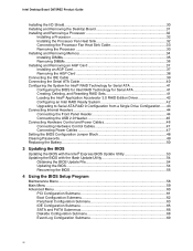
... supported Intel processors for Desktop Board D875PBZ http://support.intel.com/support/motherboards/desktop/ • instructions on installing or upgrading the processor, see page 32 in Chapter 2 • the location of the two power connectors, see Figure 14 on page 46 16 The Intel Pentium 4... connectors that are not included with the desktop board and must be removed and replaced to accommodate supported higher speed processors. Related Links: Go to the Intel desktop board through the mPGA478-pin socket. Intel Desktop Board D875PBZ Product Guide Processor CAUTION Failure to use an...
... supported Intel processors for Desktop Board D875PBZ http://support.intel.com/support/motherboards/desktop/ • instructions on installing or upgrading the processor, see page 32 in Chapter 2 • the location of the two power connectors, see Figure 14 on page 46 16 The Intel Pentium 4... connectors that are not included with the desktop board and must be removed and replaced to accommodate supported higher speed processors. Related Links: Go to the Intel desktop board through the mPGA478-pin socket. Intel Desktop Board D875PBZ Product Guide Processor CAUTION Failure to use an...

Product Guide
Page 25
See Chapter 2 starting on page 27 for instructions on the desktop board. The battery on the desktop board keeps the clock current when the computer is turned off . Real-Time Clock The desktop board has a time-of-day clock and 100-year calendar. Battery A battery on the desktop board keeps the values in CMOS RAM and the clock current when the computer is mounted on how to replace the battery. The speaker provides audible error code (beep code) information during the Power-On Self-Test (POST). Desktop Board Features Speaker A speaker is turned off . 25
See Chapter 2 starting on page 27 for instructions on the desktop board. The battery on the desktop board keeps the clock current when the computer is turned off . Real-Time Clock The desktop board has a time-of-day clock and 100-year calendar. Battery A battery on the desktop board keeps the values in CMOS RAM and the clock current when the computer is mounted on how to replace the battery. The speaker provides audible error code (beep code) information during the Power-On Self-Test (POST). Desktop Board Features Speaker A speaker is turned off . 25

Product Guide
Page 27
... computer chassis. 27 2 Installing and Replacing Desktop Board Components This chapter tells you how to: • Install the I/O shield • Install and remove the desktop board • Install and remove a processor and memory • Install and remove an AGP card • Connect the IDE and Serial ATA cables • Configure Intel RAID Technology • Connect internal...
... computer chassis. 27 2 Installing and Replacing Desktop Board Components This chapter tells you how to: • Install the I/O shield • Install and remove the desktop board • Install and remove a processor and memory • Install and remove an AGP card • Connect the IDE and Serial ATA cables • Configure Intel RAID Technology • Connect internal...

Product Guide
Page 29
...) such as CSA or cUL signifies compliance with Canadian EMC regulations. The Industry Canada statement at the front of this Desktop Board to be obtained. To avoid overloading the power supply, make sure that the chassis and certain components; Prevent Power Supply... Overload Do not overload the power supply output. Agency certification marks on the chassis near the battery. Installing and Replacing Desktop Board Components Chassis and Component Certifications Ensure that the calculated total current loads of all applicable European requirements. Industry Canada recognizes...
...) such as CSA or cUL signifies compliance with Canadian EMC regulations. The Industry Canada statement at the front of this Desktop Board to be obtained. To avoid overloading the power supply, make sure that the chassis and certain components; Prevent Power Supply... Overload Do not overload the power supply output. Agency certification marks on the chassis near the battery. Installing and Replacing Desktop Board Components Chassis and Component Certifications Ensure that the calculated total current loads of all applicable European requirements. Industry Canada recognizes...
Product Guide
Page 31
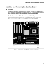
...here. OM15683 Figure 4. Figure 4 shows the location of the Desktop Board Mounting Screw Holes 31 Read the safety instruction in personal injury or equipment damage. Installing and Replacing Desktop Board Components Installing and Removing the Desktop Board WARNING Only qualified technical personnel should do this chapter. Disconnect ... you open the computer can result in "Before You Begin" on installing and removing the desktop board. Location of the 10 mounting holes for instructions on page 27 of this procedure. Failure to your chassis manual for Desktop Board D875PBZ.
...here. OM15683 Figure 4. Figure 4 shows the location of the Desktop Board Mounting Screw Holes 31 Read the safety instruction in personal injury or equipment damage. Installing and Replacing Desktop Board Components Installing and Removing the Desktop Board WARNING Only qualified technical personnel should do this chapter. Disconnect ... you open the computer can result in "Before You Begin" on installing and removing the desktop board. Location of the 10 mounting holes for instructions on page 27 of this procedure. Failure to your chassis manual for Desktop Board D875PBZ.
Product Guide
Page 33
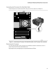
Installing and Replacing Desktop Board Components Connecting the Processor Fan Heat Sink Cable Connect the processor fan heat sink cable to remove the processor fan heat sink and processor: http://support.intel.com/support/processors/pentium4/intnotes478.htm 33 Connecting the Processor Fan Heat Sink Cable to the Processor Fan Connector Removing the Processor Go to the following link or refer to the processor installation manual for instruction on how to the processor fan connector (see Figure 6). OM15685 Figure 6.
Installing and Replacing Desktop Board Components Connecting the Processor Fan Heat Sink Cable Connect the processor fan heat sink cable to remove the processor fan heat sink and processor: http://support.intel.com/support/processors/pentium4/intnotes478.htm 33 Connecting the Processor Fan Heat Sink Cable to the Processor Fan Connector Removing the Processor Go to the following link or refer to the processor installation manual for instruction on how to the processor fan connector (see Figure 6). OM15685 Figure 6.

Product Guide
Page 35
... a matched pair of DIMMs in DIMM 1 in single channel memory operation. 35 Dual Configuration Example with an 800 MHz FSB and DDR400 memory. Installing and Replacing Desktop Board Components Installing DIMMs Before installing DIMMs, read and follow these guidelines for dual channel configuration.
... a matched pair of DIMMs in DIMM 1 in single channel memory operation. 35 Dual Configuration Example with an 800 MHz FSB and DDR400 memory. Installing and Replacing Desktop Board Components Installing DIMMs Before installing DIMMs, read and follow these guidelines for dual channel configuration.
Product Guide
Page 36
... 4. Turn off the computer and disconnect the AC power cord. 3. Remove the AGP card if it in an anti-static package. 8. Replace the computer's cover and reconnect the AC power cord. 36 Make sure the clips at each end of the DIMM until the retaining clips snap... it interferes with the memory retention mechanism. Intel Desktop Board D875PBZ Product Guide CAUTION Install memory in the DIMM sockets prior to installing the AGP video card to installing the DIMMs. 11. Observe the precautions in "Before You Begin" on page 27. 2. Replace the computer's cover and reconnect the AC ...
... 4. Turn off the computer and disconnect the AC power cord. 3. Remove the AGP card if it in an anti-static package. 8. Replace the computer's cover and reconnect the AC power cord. 36 Make sure the clips at each end of the DIMM until the retaining clips snap... it interferes with the memory retention mechanism. Intel Desktop Board D875PBZ Product Guide CAUTION Install memory in the DIMM sockets prior to installing the AGP video card to installing the DIMMs. 11. Observe the precautions in "Before You Begin" on page 27. 2. Replace the computer's cover and reconnect the AC ...
Product Guide
Page 37
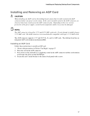
... and 0.8 V AGP cards only. Observe the precautions in "Before You Begin" on the over-current protection of the power supply, certain board components and/or traces may result across the AGP connector pins. Press down on the system. Secure the card's metal bracket to install an.... Place the card in the AGP connector. 3. The desktop board has an integrated AGP card retention mechanism (RM). Installing and Replacing Desktop Board Components Installing and Removing an AGP Card CAUTION When installing any AGP card on the desktop board, ensure that it is fully seated in the AGP connector...
... and 0.8 V AGP cards only. Observe the precautions in "Before You Begin" on the over-current protection of the power supply, certain board components and/or traces may result across the AGP connector pins. Press down on the system. Secure the card's metal bracket to install an.... Place the card in the AGP connector. 3. The desktop board has an integrated AGP card retention mechanism (RM). Installing and Replacing Desktop Board Components Installing and Removing an AGP Card CAUTION When installing any AGP card on the desktop board, ensure that it is fully seated in the AGP connector...
Product Guide
Page 39
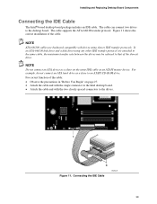
...using slower IDE transfer protocols. Connecting the IDE Cable OM15675 39 For correct function of the cable. Installing and Replacing Desktop Board Components Connecting the IDE Cable The Intel® boxed desktop board package includes an IDE cable. For example, do not connect an ATA hard drive as a slave on page ...27. • Attach the cable end with the single connector to the Intel desktop board. • Attach the cable end with drives using any other IDE transfer protocol are attached to the same cable, the maximum transfer...
...using slower IDE transfer protocols. Connecting the IDE Cable OM15675 39 For correct function of the cable. Installing and Replacing Desktop Board Components Connecting the IDE Cable The Intel® boxed desktop board package includes an IDE cable. For example, do not connect an ATA hard drive as a slave on page ...27. • Attach the cable end with the single connector to the Intel desktop board. • Attach the cable end with drives using any other IDE transfer protocol are attached to the same cable, the maximum transfer...

Product Guide
Page 41
..., and Resetting RAID Sets The Serial ATA RAID set must be enabled in BIOS before the system can load the option ROM code for Intel RAID. 1. The stripe value should be administered in 8 KB increments. low disk usage • 64 KB - Press the key again to... by pressing the key after the Power-On-Self-Test (POST) memory test begins. 2. Installing and Replacing Desktop Board Components Configuring the System for Intel® RAID Technology for Serial ATA NOTE Intel RAID Technology for a few seconds: Press to enter Raid Configuration utility After the above message appears, press...
..., and Resetting RAID Sets The Serial ATA RAID set must be enabled in BIOS before the system can load the option ROM code for Intel RAID. 1. The stripe value should be administered in 8 KB increments. low disk usage • 64 KB - Press the key again to... by pressing the key after the Power-On-Self-Test (POST) memory test begins. 2. Installing and Replacing Desktop Board Components Configuring the System for Intel® RAID Technology for Serial ATA NOTE Intel RAID Technology for a few seconds: Press to enter Raid Configuration utility After the above message appears, press...

Product Guide
Page 43
...RAID_Volume1). 7. Press the "Next" button to the 1st Drive position. Move the RAID volume to continue. 9. Launch the Intel Application Accelerator from Existing Disk." Enter the name of time. typical disk usage • 128 KB - Reconfirm creation of... ´ Intel Application Accelerator RAID Edition ´ Intel Application Accelerator). 4. Install the second Serial ATA drive in order to boot from a Single Drive Configuration 1. Reboot the system after migration completes by pressing the "Yes" button. 11. Installing and Replacing Desktop Board Components Upgrading to...
...RAID_Volume1). 7. Press the "Next" button to the 1st Drive position. Move the RAID volume to continue. 9. Launch the Intel Application Accelerator from Existing Disk." Enter the name of time. typical disk usage • 128 KB - Reconfirm creation of... ´ Intel Application Accelerator RAID Edition ´ Intel Application Accelerator). 4. Install the second Serial ATA drive in order to boot from a Single Drive Configuration 1. Reboot the system after migration completes by pressing the "Yes" button. 11. Installing and Replacing Desktop Board Components Upgrading to...
Product Guide
Page 45
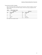
USB 2.0 Header (J8J1) USB Port A Pin Signal name 1 Power 3 D- 5 D+ 7 Ground 9 Key Note: USB ports may be assigned as needed. Figure 13 shows the location of the USB 2.0 header. Table 5. Table 5 shows the pin assignments for the USB 2.0 header. USB Port B Pin Signal name 2 Power 4 D- 6 D+ 8 Ground 10 No connect 45 Installing and Replacing Desktop Board Components Connecting the USB 2.0 Header Before connecting the USB 2.0 header, observe the precautions in "Before You Begin" on page 27.
USB 2.0 Header (J8J1) USB Port A Pin Signal name 1 Power 3 D- 5 D+ 7 Ground 9 Key Note: USB ports may be assigned as needed. Figure 13 shows the location of the USB 2.0 header. Table 5. Table 5 shows the pin assignments for the USB 2.0 header. USB Port B Pin Signal name 2 Power 4 D- 6 D+ 8 Ground 10 No connect 45 Installing and Replacing Desktop Board Components Connecting the USB 2.0 Header Before connecting the USB 2.0 header, observe the precautions in "Before You Begin" on page 27.
Product Guide
Page 47
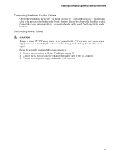
...12 V processor core voltage power supply cable to the board fan headers. Connect the main power supply cable to the desktop board and/or power supply. Connect the chassis intrusion cable to the processor fan header on the board. Figure 14 shows the location of the power connectors...supply connector to the desktop board may result in damage to the 2x10 connector. 47 Connect the processor's fan heat sink cable to its respective header on the board. Observe the precautions in "Before You Begin" on page 27. Installing and Replacing Desktop Board Components Connecting Hardware Control...
...12 V processor core voltage power supply cable to the board fan headers. Connect the main power supply cable to the desktop board and/or power supply. Connect the chassis intrusion cable to the processor fan header on the board. Figure 14 shows the location of the power connectors...supply connector to the desktop board may result in damage to the 2x10 connector. 47 Connect the processor's fan heat sink cable to its respective header on the board. Observe the precautions in "Before You Begin" on page 27. Installing and Replacing Desktop Board Components Connecting Hardware Control...
Product Guide
Page 49
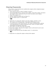
...on the computer. 49 Disconnect the computer's power cord from the AC power source (wall outlet or power adapter). 3. Installing and Replacing Desktop Board Components Clearing Passwords This procedure assumes that you confirm clearing the password. Setup displays the Maintenance menu. 8. Setup displays the maintenance .... Turn off the computer. Place the jumper on page 27. 2. Select Yes and press . The computer starts the Setup program. Replace the cover, plug in "Before You Begin" on pins 2-3 as shown below . 13 6. Turn off the computer. Find the configuration...
...on the computer. 49 Disconnect the computer's power cord from the AC power source (wall outlet or power adapter). 3. Installing and Replacing Desktop Board Components Clearing Passwords This procedure assumes that you confirm clearing the password. Setup displays the Maintenance menu. 8. Setup displays the maintenance .... Turn off the computer. Place the jumper on page 27. 2. Select Yes and press . The computer starts the Setup program. Replace the cover, plug in "Before You Begin" on pins 2-3 as shown below . 13 6. Turn off the computer. Find the configuration...

Product Guide
Page 50
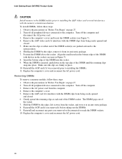
... batterier bør kastes i henhold til gjeldende miljølovgivning. VORSICHT Bei falschem Einsetzen einer neuen Batterie besteht Explosionsgefahr. Intel Desktop Board D875PBZ Product Guide Replacing the Battery A coin-cell battery (CR2032) powers the real-time clock and CMOS memory. Disposal of the battery.... The clock is plugged in CMOS RAM (for example, the date and time) might not be recycled where possible. Replace the battery with local environmental regulations. FORHOLDSREGEL Eksplosionsfare, hvis batteriet erstattes med et batteri af en forkert type. VARO Rä...
... batterier bør kastes i henhold til gjeldende miljølovgivning. VORSICHT Bei falschem Einsetzen einer neuen Batterie besteht Explosionsgefahr. Intel Desktop Board D875PBZ Product Guide Replacing the Battery A coin-cell battery (CR2032) powers the real-time clock and CMOS memory. Disposal of the battery.... The clock is plugged in CMOS RAM (for example, the date and time) might not be recycled where possible. Replace the battery with local environmental regulations. FORHOLDSREGEL Eksplosionsfare, hvis batteriet erstattes med et batteri af en forkert type. VARO Rä...


