
Product Guide
Page 4
Intel Desktop Boards D850MD and D850MV Product Guide Installing and Removing an AGP Card Retention Mechanism and Card 32 Installing the AGP Card Retention Mechanism 32 Installing an AGP Card 34 ... 59 Security Menu ...60 Power Menu ...61 APM Submenu ...62 ACPI Submenu...62 Boot Menu...63 Boot Device Priority 63 Exit Menu ...64 5 Technical Reference Board Connectors ...65 Back Panel Connectors 66 Midboard Connectors 67 Audio Connectors 67 Power and Hardware Connectors 68 Add-In Card and Peripheral Interface Connectors 70 Front...
Intel Desktop Boards D850MD and D850MV Product Guide Installing and Removing an AGP Card Retention Mechanism and Card 32 Installing the AGP Card Retention Mechanism 32 Installing an AGP Card 34 ... 59 Security Menu ...60 Power Menu ...61 APM Submenu ...62 ACPI Submenu...62 Boot Menu...63 Boot Device Priority 63 Exit Menu ...64 5 Technical Reference Board Connectors ...65 Back Panel Connectors 66 Midboard Connectors 67 Audio Connectors 67 Power and Hardware Connectors 68 Add-In Card and Peripheral Interface Connectors 70 Front...

Product Guide
Page 5
... a Memory Module 31 14. Back Panel Connectors 66 22. Location of the BIOS Configuration Jumper 37 20. Location of the Processor Fan Heatsink Base Mounting Holes 25 8. D850MV Board Power and Hardware Control Connectors 69 25. D850MD Board Add-in Card and Peripheral Interface Connectors...33 16. Audio Connectors ...67 23. Contents Desktop Board Resources 73 Memory Map ...73 DMA Channels ...73 I /O Shield 22 5. AGP Card with a Retention Notch 32 15. Connecting the IDE Cable 36 19. D850MV Board Components 10 3. D850MD Board Components 9 2. Removing the AGP Card 34 ...
... a Memory Module 31 14. Back Panel Connectors 66 22. Location of the BIOS Configuration Jumper 37 20. Location of the Processor Fan Heatsink Base Mounting Holes 25 8. D850MV Board Power and Hardware Control Connectors 69 25. D850MD Board Add-in Card and Peripheral Interface Connectors...33 16. Audio Connectors ...67 23. Contents Desktop Board Resources 73 Memory Map ...73 DMA Channels ...73 I /O Shield 22 5. AGP Card with a Retention Notch 32 15. Connecting the IDE Cable 36 19. D850MV Board Components 10 3. D850MD Board Components 9 2. Removing the AGP Card 34 ...

Product Guide
Page 6
D850MV Board Add-in Card and Peripheral Interface Connectors 71 27. Front Panel Connectors 72 Tables 1. RJ-45 LAN Connector LEDs 17 4. Extended Configuration Submenu 49 10. Advanced Menu ...51 12. PCI Configuration Submenu ...Submenus 57 17. ACPI Submenu ...62 24. I/O Map...74 30. Event Log Configuration Submenu 59 19. Interrupts ...76 31. Intel Desktop Boards D850MD and D850MV Product Guide 26. Processors Supported by the Desktop Board 11 3. Maintenance Menu ...48 9. Main Menu ...50 11. Diskette Configuration Submenu 58 18. Video Configuration Submenu 59 20. ...
D850MV Board Add-in Card and Peripheral Interface Connectors 71 27. Front Panel Connectors 72 Tables 1. RJ-45 LAN Connector LEDs 17 4. Extended Configuration Submenu 49 10. Advanced Menu ...51 12. PCI Configuration Submenu ...Submenus 57 17. ACPI Submenu ...62 24. I/O Map...74 30. Event Log Configuration Submenu 59 19. Interrupts ...76 31. Intel Desktop Boards D850MD and D850MV Product Guide 26. Processors Supported by the Desktop Board 11 3. Maintenance Menu ...48 9. Main Menu ...50 11. Diskette Configuration Submenu 58 18. Video Configuration Submenu 59 20. ...

Product Guide
Page 7
...Desktop Board Features ✏ NOTE The D850MD board layout was used for up to the optional CNR • Two IDE interfaces with Ultra DMA-33 and ATA-66/100 support • One floppy drive interface • One parallel port • Two serial ports • PS/2† keyboard and mouse ports D850MD board... • Up to seven Universal Serial Bus (USB) ports Four ports routed to the back panel Two ports routed to the front panel USB connector One port routed to 2 GB of system memory Intel® 850 chipset, consisting of the D850MD and D850MV boards.
...Desktop Board Features ✏ NOTE The D850MD board layout was used for up to the optional CNR • Two IDE interfaces with Ultra DMA-33 and ATA-66/100 support • One floppy drive interface • One parallel port • Two serial ports • PS/2† keyboard and mouse ports D850MD board... • Up to seven Universal Serial Bus (USB) ports Four ports routed to the back panel Two ports routed to the front panel USB connector One port routed to 2 GB of system memory Intel® 850 chipset, consisting of the D850MD and D850MV boards.

Product Guide
Page 8
Intel Desktop Boards D850MD and D850MV Product Guide Table 1. Feature Summary (continued) BIOS • Intel/AMI BIOS • 4 Mbit symmetrical flash memory • Support for SMBIOS Power Management • Support for Advanced ... and front panel Other Features • SCSI hard drive activity LED connector for the front panel • Speaker ✏ NOTE For information about Intel® desktop boards, including technical product specifications, BIOS updates, and device drivers, go to the Intel World Wide Web site at: http://support.intel.com/support/motherboards/desktop 8
Intel Desktop Boards D850MD and D850MV Product Guide Table 1. Feature Summary (continued) BIOS • Intel/AMI BIOS • 4 Mbit symmetrical flash memory • Support for SMBIOS Power Management • Support for Advanced ... and front panel Other Features • SCSI hard drive activity LED connector for the front panel • Speaker ✏ NOTE For information about Intel® desktop boards, including technical product specifications, BIOS updates, and device drivers, go to the Intel World Wide Web site at: http://support.intel.com/support/motherboards/desktop 8

Product Guide
Page 9
...connector C AGP connector R Front panel USB connector D CD-ROM connector (ATAPI) S Alternate power/sleep LED connector E Front panel audio connector T Front panel connector F Chassis intrusion connector U Chassis fan connector (fan 2) (tachometer input) G Back panel connectors V Battery H ATX12V processor ... Z Intel 82801BA I/O Controller Hub (ICH2) L RIMM sockets AA PCI bus add-in card connectors M RIMM fan connector (fan 1) BB Communication and Networking Riser (CNR) N Power connector (optional) O Floppy drive connector Figure 1. Desktop Board Features Board Components ...
...connector C AGP connector R Front panel USB connector D CD-ROM connector (ATAPI) S Alternate power/sleep LED connector E Front panel audio connector T Front panel connector F Chassis intrusion connector U Chassis fan connector (fan 2) (tachometer input) G Back panel connectors V Battery H ATX12V processor ... Z Intel 82801BA I/O Controller Hub (ICH2) L RIMM sockets AA PCI bus add-in card connectors M RIMM fan connector (fan 1) BB Communication and Networking Riser (CNR) N Power connector (optional) O Floppy drive connector Figure 1. Desktop Board Features Board Components ...

Product Guide
Page 10
... Secondary IDE connector C AGP connector R Front panel USB connector D CD-ROM connector (ATAPI) S Alternate power/sleep LED connector E Front panel audio connector T Front panel connector F Chassis intrusion connector U Chassis fan connector (fan 2) (tachometer input) G Back panel connectors V Battery H ATX12V processor core voltage ... N Power connector (optional) O Floppy drive connector CC Chassis fan connector (fan 3) Figure 2. D850MV Board Components 10 Intel Desktop Boards D850MD and D850MV Product Guide Figure 2 shows the location of the major components on the...
... Secondary IDE connector C AGP connector R Front panel USB connector D CD-ROM connector (ATAPI) S Alternate power/sleep LED connector E Front panel audio connector T Front panel connector F Chassis intrusion connector U Chassis fan connector (fan 2) (tachometer input) G Back panel connectors V Battery H ATX12V processor core voltage ... N Power connector (optional) O Floppy drive connector CC Chassis fan connector (fan 3) Figure 2. D850MV Board Components 10 Intel Desktop Boards D850MD and D850MV Product Guide Figure 2 shows the location of the major components on the...

Product Guide
Page 14
Intel Desktop Boards D850MD and D850MV Product Guide USB Support The boards suppport up to the optional CNR. four ports routed to the back panel, two to the front panel connector, and one to seven USB ports; To attach additional devices, connect an external hub to either of information between the... bus connector 3 slot shared with CNR) • One AGP connector • One optional CNR connector (slot shared with PCI bus connector 3) The D850MV board has: • Five PCI bus add-in ports. Use a shielded cable that have an unshielded cable attached to a USB port might not meet ...
Intel Desktop Boards D850MD and D850MV Product Guide USB Support The boards suppport up to the optional CNR. four ports routed to the back panel, two to the front panel connector, and one to seven USB ports; To attach additional devices, connect an external hub to either of information between the... bus connector 3 slot shared with CNR) • One AGP connector • One optional CNR connector (slot shared with PCI bus connector 3) The D850MV board has: • Five PCI bus add-in ports. Use a shielded cable that have an unshielded cable attached to a USB port might not meet ...

Product Guide
Page 15
...your computer, the PCI auto-configuration utility in Chapter 3 on the back panel, is a high-performance interface for graphics-intensive applications such as audio, modem, USB, and LAN interfaces of the Intel 850 chipset. AGP is independent of the following the instructions in the ... audio quality may be included with the boxed desktop board to this output. An AGP card retention mechanism (RM) may occur if passive (non-amplified) speakers are available from Intel's World Wide Web site: http://support.intel.com/support/motherboards/desktop BIOS The BIOS provides the Power-On Self-Test...
...your computer, the PCI auto-configuration utility in Chapter 3 on the back panel, is a high-performance interface for graphics-intensive applications such as audio, modem, USB, and LAN interfaces of the Intel 850 chipset. AGP is independent of the following the instructions in the ... audio quality may be included with the boxed desktop board to this output. An AGP card retention mechanism (RM) may occur if passive (non-amplified) speakers are available from Intel's World Wide Web site: http://support.intel.com/support/motherboards/desktop BIOS The BIOS provides the Power-On Self-Test...

Product Guide
Page 18
...power LED on the front panel, the sleep state is used with an ACPI-aware operating system, the BIOS can damage the power supply and/or affect ACPI S3 sleep state functionality. When signaled by the LED turning amber. 18 Intel Desktop Boards D850MD and D850MV Product Guide Power Management Features... Resume on Ring Wake from USB Wake from the PCI and/or USB buses exceeds power supply capacity, the desktop board may lose register settings stored in the S3 sleep state, the computer will appear to be capable of providing adequate +5 V standby current. CAUTION...
...power LED on the front panel, the sleep state is used with an ACPI-aware operating system, the BIOS can damage the power supply and/or affect ACPI S3 sleep state functionality. When signaled by the LED turning amber. 18 Intel Desktop Boards D850MD and D850MV Product Guide Power Management Features... Resume on Ring Wake from USB Wake from the PCI and/or USB buses exceeds power supply capacity, the desktop board may lose register settings stored in the S3 sleep state, the computer will appear to be capable of providing adequate +5 V standby current. CAUTION...

Product Guide
Page 21
...81 for using an antistatic wrist strap and a conductive foam pad. 2 Installing and Replacing Desktop Board Components This chapter tells you how to: • Install the I/O shield • Install and remove the desktop board • Install and remove a processor • Install and remove memory • Install...Clear passwords • Replace the battery Before You Begin CAUTION Before you install this board in a chassis, see Appendix B on the board can continue to operate even though the front panel power button is not available, you can provide some ESD protection by wearing an ...
...81 for using an antistatic wrist strap and a conductive foam pad. 2 Installing and Replacing Desktop Board Components This chapter tells you how to: • Install the I/O shield • Install and remove the desktop board • Install and remove a processor • Install and remove memory • Install...Clear passwords • Replace the battery Before You Begin CAUTION Before you install this board in a chassis, see Appendix B on the board can continue to operate even though the front panel power button is not available, you can provide some ESD protection by wearing an ...

Product Guide
Page 34
Removing the AGP Card from the Retention Mechanism Follow these instructions to the chassis back panel with a screw. B E A C D Figure 16. Remove the screw (B) that secures the card's metal bracket (A) to remove an AGP card from the AGP card RM: 1. Press ... 34 Pull the card straight up (E). Secure the card's metal bracket to install an AGP card: 1. Intel Desktop Boards D850MD and D850MV Product Guide Installing an AGP Card Follow these instructions to the chassis back panel. 2. Place the AGP card in the AGP connector and the card retention notch snaps into place around the...
Removing the AGP Card from the Retention Mechanism Follow these instructions to the chassis back panel with a screw. B E A C D Figure 16. Remove the screw (B) that secures the card's metal bracket (A) to remove an AGP card from the AGP card RM: 1. Press ... 34 Pull the card straight up (E). Secure the card's metal bracket to install an AGP card: 1. Intel Desktop Boards D850MD and D850MV Product Guide Installing an AGP Card Follow these instructions to the chassis back panel. 2. Place the AGP card in the AGP connector and the card retention notch snaps into place around the...

Product Guide
Page 65
... provide operating voltage (+5 V dc and +12 V dc, for powering devices external to the computer chassis. 5 Technical Reference Board Connectors The board connectors can be divided into three groups: • Back panel connectors • Midboard connectors Audio connectors Power and hardware connectors Add-in the load presented by the external devices...
... provide operating voltage (+5 V dc and +12 V dc, for powering devices external to the computer chassis. 5 Technical Reference Board Connectors The board connectors can be divided into three groups: • Back panel connectors • Midboard connectors Audio connectors Power and hardware connectors Add-in the load presented by the external devices...
Product Guide
Page 66
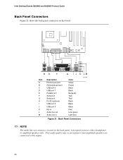
... may occur if passive (non-amplified) speakers are connected to power either headphones or amplified speakers only. Intel Desktop Boards D850MD and D850MV Product Guide Back Panel Connectors Figure 21 shows the back panel connectors on the back panel, is designed to this output. 66 Back Panel Connectors ✏ NOTE The audio line out connector, located on the...
... may occur if passive (non-amplified) speakers are connected to power either headphones or amplified speakers only. Intel Desktop Boards D850MD and D850MV Product Guide Back Panel Connectors Figure 21 shows the back panel connectors on the back panel, is designed to this output. 66 Back Panel Connectors ✏ NOTE The audio line out connector, located on the...
Product Guide
Page 67
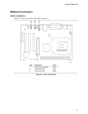
A BC 4 4 1 1 Technical Reference Item A B C Description Auxiliary line in (ATAPI) CD-ROM (ATAPI) Front panel audio Color White Black Black Figure 22. Audio Connectors OM11838 67 Midboard Connectors Audio Connectors Figure 22 shows the location of the audio connectors.
A BC 4 4 1 1 Technical Reference Item A B C Description Auxiliary line in (ATAPI) CD-ROM (ATAPI) Front panel audio Color White Black Black Figure 22. Audio Connectors OM11838 67 Midboard Connectors Audio Connectors Figure 22 shows the location of the audio connectors.
Product Guide
Page 72
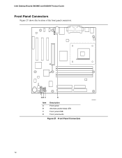
Intel Desktop Boards D850MD and D850MV Product Guide Front Panel Connectors Figure 27 shows the location of the front panel connectors. 1 12 1 12 10 16 7 15 ABC D Item A B C D Description Front panel Alternate power/sleep LED Front panel USB Front panel audio Figure 27. Front Panel Connectors OM11841 72
Intel Desktop Boards D850MD and D850MV Product Guide Front Panel Connectors Figure 27 shows the location of the front panel connectors. 1 12 1 12 10 16 7 15 ABC D Item A B C D Description Front panel Alternate power/sleep LED Front panel USB Front panel audio Figure 27. Front Panel Connectors OM11841 72


