
Product Guide
Page 4
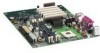
Intel Desktop Boards D850MD and D850MV Product Guide Installing and Removing an AGP Card Retention Mechanism and Card 32 Installing the AGP Card Retention Mechanism 32 Installing an AGP Card 34 ... Log Configuration Submenu 59 Video Configuration Submenu 59 Security Menu ...60 Power Menu ...61 APM Submenu ...62 ACPI Submenu...62 Boot Menu...63 Boot Device Priority 63 Exit Menu ...64 5 Technical Reference Board Connectors ...65 Back Panel Connectors 66 Midboard Connectors 67 Audio Connectors 67 Power and Hardware Connectors 68 Add-In Card...
Intel Desktop Boards D850MD and D850MV Product Guide Installing and Removing an AGP Card Retention Mechanism and Card 32 Installing the AGP Card Retention Mechanism 32 Installing an AGP Card 34 ... Log Configuration Submenu 59 Video Configuration Submenu 59 Security Menu ...60 Power Menu ...61 APM Submenu ...62 ACPI Submenu...62 Boot Menu...63 Boot Device Priority 63 Exit Menu ...64 5 Technical Reference Board Connectors ...65 Back Panel Connectors 66 Midboard Connectors 67 Audio Connectors 67 Power and Hardware Connectors 68 Add-In Card...

Product Guide
Page 6
... ...7 2. RJ-45 LAN Connector LEDs 17 4. Primary/Secondary IDE Master/Slave Submenus 57 17. DMA Channels...73 29. Beep Codes ...77 32. Intel Desktop Boards D850MD and D850MV Product Guide 26. EMC Regulations ...81 vi Boot Configuration Submenu 53 14. I/O Map...74 30. Interrupts ...76 31. BIOS Error Messages 78 33. Processors Supported by the...
... ...7 2. RJ-45 LAN Connector LEDs 17 4. Primary/Secondary IDE Master/Slave Submenus 57 17. DMA Channels...73 29. Beep Codes ...77 32. Intel Desktop Boards D850MD and D850MV Product Guide 26. EMC Regulations ...81 vi Boot Configuration Submenu 53 14. I/O Map...74 30. Interrupts ...76 31. BIOS Error Messages 78 33. Processors Supported by the...

Product Guide
Page 16
...who can boot the computer. You do not need to run the BIOS Setup program after installing an IDE device. To use ATA-66/100 features, the following restrictions: • The supervisor password gives unrestricted access to view and change all Setup options. Intel Desktop Boards D850MD and D850MV Product ...Guide IDE Auto Configuration If you must enter either password to boot the computer. 16
...who can boot the computer. You do not need to run the BIOS Setup program after installing an IDE device. To use ATA-66/100 features, the following restrictions: • The supervisor password gives unrestricted access to view and change all Setup options. Intel Desktop Boards D850MD and D850MV Product ...Guide IDE Auto Configuration If you must enter either password to boot the computer. 16

Product Guide
Page 29
...memory module sockets arranged as shown in bank 0 first. The pair of RDRAM components installed in any unused memory connector or the board will not boot. The board supports combinations of a RIMM module or a CRIMM module in bank 1 (see Figure 3 on page 12. or double-sided...CRIMMs in the sockets in a RIMM connector can damage the D850MD and D850MV boards. If the total number of sockets closest to do so could damage the memory and the board. Installing and Replacing Desktop Board Components Installing and Removing Memory CAUTIONS Before installing or removing RIMM modules,...
...memory module sockets arranged as shown in bank 0 first. The pair of RDRAM components installed in any unused memory connector or the board will not boot. The board supports combinations of a RIMM module or a CRIMM module in bank 1 (see Figure 3 on page 12. or double-sided...CRIMMs in the sockets in a RIMM connector can damage the D850MD and D850MV boards. If the total number of sockets closest to do so could damage the memory and the board. Installing and Replacing Desktop Board Components Installing and Removing Memory CAUTIONS Before installing or removing RIMM modules,...

Product Guide
Page 37
Table 5 shows the jumper settings for booting. Location of the board's BIOS configuration jumper (J9H2) is required. 37 The BIOS attempts to be done in BIOS Setup. Table 5. Use this menu to clear passwords. After the ... is shown in unreliable computer operation. Moving the jumper with the power on may result in Figure 19. 1 3 J9H2 OM11836 Figure 19. Installing and Replacing Desktop Board Components Setting the BIOS Configuration Jumper CAUTION Always turn off the power and unplug the power cord from the computer before changing the jumper.
Table 5 shows the jumper settings for booting. Location of the board's BIOS configuration jumper (J9H2) is required. 37 The BIOS attempts to be done in BIOS Setup. Table 5. Use this menu to clear passwords. After the ... is shown in unreliable computer operation. Moving the jumper with the power on may result in Figure 19. 1 3 J9H2 OM11836 Figure 19. Installing and Replacing Desktop Board Components Setting the BIOS Configuration Jumper CAUTION Always turn off the power and unplug the power cord from the computer before changing the jumper.

Product Guide
Page 38
... values and exit Setup. 10. Replace the cover, plug in "Before You Begin" on the computer, and allow it to boot. 7. Turn off the computer. Replace the cover, plug in the computer and the configuration jumper is installed in the computer, turn...and press . Press and Setup displays a pop-up screen requesting that the board is set to the computer. Press to select Clear Passwords. Find the configuration jumper (see Figure 19). 5. Intel Desktop Boards D850MD and D850MV Product Guide Clearing Passwords This procedure assumes that you confirm clearing the password. Disconnect...
... values and exit Setup. 10. Replace the cover, plug in "Before You Begin" on the computer, and allow it to boot. 7. Turn off the computer. Replace the cover, plug in the computer and the configuration jumper is installed in the computer, turn...and press . Press and Setup displays a pop-up screen requesting that the board is set to the computer. Press to select Clear Passwords. Find the configuration jumper (see Figure 19). 5. Intel Desktop Boards D850MD and D850MV Product Guide Clearing Passwords This procedure assumes that you confirm clearing the password. Disconnect...
Product Guide
Page 44
.... The recovery process will interrupt the BIOS update; Intel Desktop Boards D850MD and D850MV Product Guide ✏ NOTE Please review the instructions distributed with the update files will not see Figure 19). 3. The Intel Flash Memory Update Utility allows you to remove the diskette and to boot. Do not interrupt the process or the system may...
.... The recovery process will interrupt the BIOS update; Intel Desktop Boards D850MD and D850MV Product Guide ✏ NOTE Please review the instructions distributed with the update files will not see Figure 19). 3. The Intel Flash Memory Update Utility allows you to remove the diskette and to boot. Do not interrupt the process or the system may...

Product Guide
Page 45
... successful recovery of continuous beeps indicates a failed BIOS recovery. 7. Drive A activity will begin again followed by two more beeps indicating the successful recovery of the boot block. Turn on pins 1-2 as shown below to set normal mode for Setup. 1 3 11. If recovery is successful, turn off the computer, and disconnect its...
... successful recovery of continuous beeps indicates a failed BIOS recovery. 7. Drive A activity will begin again followed by two more beeps indicating the successful recovery of the boot block. Turn on pins 1-2 as shown below to set normal mode for Setup. 1 3 11. If recovery is successful, turn off the computer, and disconnect its...
Product Guide
Page 47
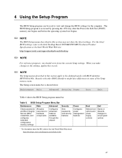
... Allocates resources for the computer. Maintenance Main Advanced Security Power Boot Exit Table 6 shows the BIOS Setup program menu bar. For the latest BIOS settings, refer to the Intel Desktop Board D850MD/D850MV Technical Product Specification or the Intel World Wide Web site: http://support.intel.com/support/motherboards/desktop ✏ NOTE For reference purposes, you make changes to...
... Allocates resources for the computer. Maintenance Main Advanced Security Power Boot Exit Table 6 shows the BIOS Setup program menu bar. For the latest BIOS settings, refer to the Intel Desktop Board D850MD/D850MV Technical Product Specification or the Intel World Wide Web site: http://support.intel.com/support/motherboards/desktop ✏ NOTE For reference purposes, you make changes to...

Product Guide
Page 48
...about setting configure mode. See page 37 for menu screens. Clears the user and administrative passwords. Displays processor information. Intel Desktop Boards D850MD and D850MV Product Guide Table 7 shows the function keys available for information about the BIS, refer to clear the Setup passwords and...or down Moves cursor to the next field Executes command or selects the submenu Load the default configuration values for Management Boot Integrity Service (BIS) credentials. Invokes the Extended Configuration submenu. Displays the processor's stepping signature. Clears the Wired ...
...about setting configure mode. See page 37 for menu screens. Clears the user and administrative passwords. Displays processor information. Intel Desktop Boards D850MD and D850MV Product Guide Table 7 shows the function keys available for information about the BIS, refer to clear the Setup passwords and...or down Moves cursor to the next field Executes command or selects the submenu Load the default configuration values for Management Boot Integrity Service (BIS) credentials. Invokes the Extended Configuration submenu. Displays the processor's stepping signature. Clears the Wired ...
Product Guide
Page 49
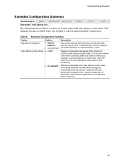
... program order. This setting identifies the video memory range as required. Using the Setup Program Extended Configuration Submenu Maintenance Main Advanced Security Extended Configuration Power Boot Exit The submenu shown in Table 9 is selected under Extended Configuration. Selects Uncacheable Speculative Write-Combining (USWC) video memory cache mode. Well suited for applications...
... program order. This setting identifies the video memory range as required. Using the Setup Program Extended Configuration Submenu Maintenance Main Advanced Security Extended Configuration Power Boot Exit The submenu shown in Table 9 is selected under Extended Configuration. Selects Uncacheable Speculative Write-Combining (USWC) video memory cache mode. Well suited for applications...
Product Guide
Page 50
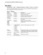
... is used by the BIOS. Displays processor type. Specifies the current time. This menu reports processor and memory information and is ECC-capable. Table 10. Intel Desktop Boards D850MD and D850MV Product Guide Main Menu Maintenance Main Advanced Security Power Boot Exit Table 10 describes the Main Menu.
... is used by the BIOS. Displays processor type. Specifies the current time. This menu reports processor and memory information and is ECC-capable. Table 10. Intel Desktop Boards D850MD and D850MV Product Guide Main Menu Maintenance Main Advanced Security Power Boot Exit Table 10 describes the Main Menu.

Product Guide
Page 51
...Peripheral Configuration submenu. When selected, displays the Event Log Configuration submenu. When selected, displays the Boot Configuration submenu. When selected, displays the Diskette Configuration submenu. Advanced Menu Feature Options Extended Configuration No options PCI Configuration No ... When selected, displays the Video Configuration submenu. 51 Using the Setup Program Advanced Menu Maintenance Main Advanced Security Power Boot Exit Table 11 describes the Advanced Menu. This menu is highlighted, User-Defined has been selected in Extended Configuration ...
...Peripheral Configuration submenu. When selected, displays the Event Log Configuration submenu. When selected, displays the Boot Configuration submenu. When selected, displays the Diskette Configuration submenu. Advanced Menu Feature Options Extended Configuration No options PCI Configuration No ... When selected, displays the Video Configuration submenu. 51 Using the Setup Program Advanced Menu Maintenance Main Advanced Security Power Boot Exit Table 11 describes the Advanced Menu. This menu is highlighted, User-Defined has been selected in Extended Configuration ...

Product Guide
Page 52
...Table 12 is used to configure the IRQ priority of PCI slots individually. Table 12. Selections made to Auto (D850MV only). 52 PCI Configuration Submenu Feature PCI Slot 1 IRQ Priority PCI Slot 2 IRQ Priority PCI Slot 3 ...8226; 11 No options Description Allows selection of IRQ priority (D850MV only). Allows selection of IRQ priority. Intel Desktop Boards D850MD and D850MV Product Guide PCI Configuration Submenu Maintenance Main Advanced Security Power PCI Configuration Boot Configuration Peripheral Configuration IDE Configuration Diskette Configuration Event Log Configuration Video ...
...Table 12 is used to configure the IRQ priority of PCI slots individually. Table 12. Selections made to Auto (D850MV only). 52 PCI Configuration Submenu Feature PCI Slot 1 IRQ Priority PCI Slot 2 IRQ Priority PCI Slot 3 ...8226; 11 No options Description Allows selection of IRQ priority (D850MV only). Allows selection of IRQ priority. Intel Desktop Boards D850MD and D850MV Product Guide PCI Configuration Submenu Maintenance Main Advanced Security Power PCI Configuration Boot Configuration Peripheral Configuration IDE Configuration Diskette Configuration Event Log Configuration Video ...

Product Guide
Page 53
... the Numlock feature on state of the keyboard. 53 No does not clear the PCI/PnP configuration data stored in flash memory on the next boot. Boot Configuration Submenu Feature Plug & Play O/S Reset Config Data Numlock Options • No (default) • Yes • No (default) • Yes • Off • On (default...
... the Numlock feature on state of the keyboard. 53 No does not clear the PCI/PnP configuration data stored in flash memory on the next boot. Boot Configuration Submenu Feature Plug & Play O/S Reset Config Data Numlock Options • No (default) • Yes • No (default) • Yes • Off • On (default...

Product Guide
Page 54
... base I/O address for serial port B, if serial port B is set to Enabled. Intel Desktop Boards D850MD and D850MV Product Guide Peripheral Configuration Submenu Maintenance Main Advanced Security Power PCI Configuration Boot Configuration Peripheral Configuration IDE Configuration Diskette Configuration Event Log Configuration Video Configuration Boot Exit This submenu shown in Table 14 is set to Enabled. continued...
... base I/O address for serial port B, if serial port B is set to Enabled. Intel Desktop Boards D850MD and D850MV Product Guide Peripheral Configuration Submenu Maintenance Main Advanced Security Power PCI Configuration Boot Configuration Peripheral Configuration IDE Configuration Diskette Configuration Event Log Configuration Video Configuration Boot Exit This submenu shown in Table 14 is set to Enabled. continued...

Product Guide
Page 56
... options Secondary IDE Slave No options Description Specifies the integrated IDE controller. Intel Desktop Boards D850MD and D850MV Product Guide IDE Configuration Submenu Maintenance Main Advanced Security Power PCI Configuration Boot Configuration Peripheral Configuration IDE Configuration Diskette Configuration Event Log Configuration Video Configuration Boot This submenu shown in Table 15 is used to configure IDE device...
... options Secondary IDE Slave No options Description Specifies the integrated IDE controller. Intel Desktop Boards D850MD and D850MV Product Guide IDE Configuration Submenu Maintenance Main Advanced Security Power PCI Configuration Boot Configuration Peripheral Configuration IDE Configuration Diskette Configuration Event Log Configuration Video Configuration Boot This submenu shown in Table 15 is used to configure IDE device...
Product Guide
Page 57
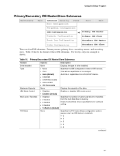
... example is installed). • 0 • 1 • 2 • 3 • 4 continued 57 Using the Setup Program Primary/Secondary IDE Master/Slave Submenus Maintenance Main Advanced Security Boot Configuration Power Boot Exit Peripheral Configuration IDE Configuration Diskette Configuration ➜ Primary IDE Master Primary IDE Slave Event Log Configuration Secondary IDE Master Video Configuration Secondary IDE...
... example is installed). • 0 • 1 • 2 • 3 • 4 continued 57 Using the Setup Program Primary/Secondary IDE Master/Slave Submenus Maintenance Main Advanced Security Boot Configuration Power Boot Exit Peripheral Configuration IDE Configuration Diskette Configuration ➜ Primary IDE Master Primary IDE Slave Event Log Configuration Secondary IDE Master Video Configuration Secondary IDE...
Product Guide
Page 58
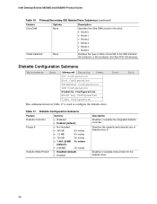
...• Mode 3 • Mode 4 • Mode 5 Displays the type of diskette drive A. Diskette Configuration Submenu Maintenance Main Advanced Security Power PCI Configuration Boot Configuration Peripheral Configuration IDE Configuration Diskette Configuration Event Log Configuration Video Configuration This submenu shown in Table 17 is used to the IDE interface: 40... Feature Options Description Ultra DMA None Cable Detected None Specifies the Ultra DMA mode for the diskette drive. 58 Intel Desktop Boards D850MD and D850MV Product Guide Table 16. Boot Exit Table 17.
...• Mode 3 • Mode 4 • Mode 5 Displays the type of diskette drive A. Diskette Configuration Submenu Maintenance Main Advanced Security Power PCI Configuration Boot Configuration Peripheral Configuration IDE Configuration Diskette Configuration Event Log Configuration Video Configuration This submenu shown in Table 17 is used to the IDE interface: 40... Feature Options Description Ultra DMA None Cable Detected None Specifies the Ultra DMA mode for the diskette drive. 58 Intel Desktop Boards D850MD and D850MV Product Guide Table 16. Boot Exit Table 17.

Product Guide
Page 59
... there is space available in the event log. Video Configuration Submenu Maintenance Main Advanced Security Power PCI Configuration Boot Configuration Peripheral Configuration IDE Configuration Diskette Configuration Event Log Configuration Video Configuration The submenu shown in Table 19 is... Event Log Configuration Submenu Maintenance Main Advanced Security Power PCI Configuration Boot Configuration Peripheral Configuration IDE Configuration Diskette Configuration Event Log Configuration Video Configuration Boot The submenu shown in Table 18 is used to configure video features...
... there is space available in the event log. Video Configuration Submenu Maintenance Main Advanced Security Power PCI Configuration Boot Configuration Peripheral Configuration IDE Configuration Diskette Configuration Event Log Configuration Video Configuration The submenu shown in Table 19 is... Event Log Configuration Submenu Maintenance Main Advanced Security Power PCI Configuration Boot Configuration Peripheral Configuration IDE Configuration Diskette Configuration Event Log Configuration Video Configuration Boot The submenu shown in Table 18 is used to configure video features...


