

Product Guide
Page 3
... Desktop Board Features Desktop Board Components 9 Processor ...11 Main Memory ...12 Intel® 850E Chipset ...12 Intel® 82850E Memory Controller Hub (MCH 12 Intel® 82801BA I/O Controller Hub (ICH2 13 Firmware Hub (FWH 13 Input/Output (I/O) Controller 13 Real-Time Clock...13 USB Support ...14 PCI Enhanced IDE Interface 14 Expansion Slots...14 AGP Connector ...15 Communication and Networking Riser (CNR) (Optional 15 Audio Subsystem ...15 BIOS ...15 PCI Auto Configuration 15 IDE Auto Configuration 16 Security Passwords ...16 LAN Subsystem (Optional 16 LAN Subsystem Software...
... Desktop Board Features Desktop Board Components 9 Processor ...11 Main Memory ...12 Intel® 850E Chipset ...12 Intel® 82850E Memory Controller Hub (MCH 12 Intel® 82801BA I/O Controller Hub (ICH2 13 Firmware Hub (FWH 13 Input/Output (I/O) Controller 13 Real-Time Clock...13 USB Support ...14 PCI Enhanced IDE Interface 14 Expansion Slots...14 AGP Connector ...15 Communication and Networking Riser (CNR) (Optional 15 Audio Subsystem ...15 BIOS ...15 PCI Auto Configuration 15 IDE Auto Configuration 16 Security Passwords ...16 LAN Subsystem (Optional 16 LAN Subsystem Software...
Product Guide
Page 4
Intel Desktop Boards D850EMD2 and D850EMV2 Product Guide 3 Updating the BIOS Updating the BIOS with the Intel® Express BIOS Update Utility 35 Updating the BIOS with the Intel® Flash Memory Update Utility 35 Obtaining the BIOS Update File 35 Updating the BIOS...36 Recovering the BIOS 36 4 Using the Setup Program Maintenance Menu...40 Extended Configuration Submenu 41 Main Menu ...42 Advanced Menu ...43 PCI Configuration Submenu 44 Boot Configuration Submenu 45 Peripheral Configuration Submenu 46 IDE Configuration Submenu 48 Primary/Secondary IDE Master/Slave Submenus 49 ...
Intel Desktop Boards D850EMD2 and D850EMV2 Product Guide 3 Updating the BIOS Updating the BIOS with the Intel® Express BIOS Update Utility 35 Updating the BIOS with the Intel® Flash Memory Update Utility 35 Obtaining the BIOS Update File 35 Updating the BIOS...36 Recovering the BIOS 36 4 Using the Setup Program Maintenance Menu...40 Extended Configuration Submenu 41 Main Menu ...42 Advanced Menu ...43 PCI Configuration Submenu 44 Boot Configuration Submenu 45 Peripheral Configuration Submenu 46 IDE Configuration Submenu 48 Primary/Secondary IDE Master/Slave Submenus 49 ...
Product Guide
Page 5
... 76 Use Only for the BIOS Setup Program Modes (J9H2 30 6. RDRAM and CRIMM Installation 25 10. Removing the Battery...34 16. Desktop Board D850EMD2 Add-in Card and Peripheral Interface Connectors 63 22. Standby Current Requirements 19 5. BIOS Setup Program Function Keys 40 8. Location of the BIOS Configuration Jumper 30 15. RIMM Installation ...26 11. Connecting the IDE Cable 29 14. Back Panel Connectors...58 17. Jumper Settings for Intended Applications 77 Figures 1. Main Menu ...42 11. PCI Configuration...
... 76 Use Only for the BIOS Setup Program Modes (J9H2 30 6. RDRAM and CRIMM Installation 25 10. Removing the Battery...34 16. Desktop Board D850EMD2 Add-in Card and Peripheral Interface Connectors 63 22. Standby Current Requirements 19 5. BIOS Setup Program Function Keys 40 8. Location of the BIOS Configuration Jumper 30 15. RIMM Installation ...26 11. Connecting the IDE Cable 29 14. Back Panel Connectors...58 17. Jumper Settings for Intended Applications 77 Figures 1. Main Menu ...42 11. PCI Configuration...

Product Guide
Page 10
...Battery G Back panel connectors W Speaker H ATX12V processor core voltage connector X BIOS configuration jumper I Processor fan connector (CPU fan) (tachometer input) Y SCSI hard drive activity LED connector J Intel 82850E Memory Controller Hub (MCH) Z Intel 82801BA I/O Controller Hub (ICH2) K Processor socket AA NEC D720100AGM USB 2.0 controller L RIMM sockets BB PCI bus add-in card connectors M RIMM fan connector (fan 1) CC Communication and Networking Riser (CNR) (optional) N Power connector DD Chassis fan connector (fan 3) O Floppy drive connector P Primary IDE connector...
...Battery G Back panel connectors W Speaker H ATX12V processor core voltage connector X BIOS configuration jumper I Processor fan connector (CPU fan) (tachometer input) Y SCSI hard drive activity LED connector J Intel 82850E Memory Controller Hub (MCH) Z Intel 82801BA I/O Controller Hub (ICH2) K Processor socket AA NEC D720100AGM USB 2.0 controller L RIMM sockets BB PCI bus add-in card connectors M RIMM fan connector (fan 1) CC Communication and Networking Riser (CNR) (optional) N Power connector DD Chassis fan connector (fan 3) O Floppy drive connector P Primary IDE connector...
Product Guide
Page 11
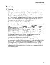
... micron process in an mPGA478 package Intel Pentium 4 processor on page 21. Desktop Board Features Processor CAUTION Failure to use an ATX12V power supply, or not connecting the additional power supply lead to the Desktop Board D850EMD2 or D850EMV2 may be purchased separately. The processor connects to desktop board specifications. Both desktop boards have two ATX12V compliant power supply connectors that are not included with the desktop board and must be removed and replaced to accommodate supported higher speed processors. Table 2.
... micron process in an mPGA478 package Intel Pentium 4 processor on page 21. Desktop Board Features Processor CAUTION Failure to use an ATX12V power supply, or not connecting the additional power supply lead to the Desktop Board D850EMD2 or D850EMV2 may be purchased separately. The processor connects to desktop board specifications. Both desktop boards have two ATX12V compliant power supply connectors that are not included with the desktop board and must be removed and replaced to accommodate supported higher speed processors. Table 2.

Product Guide
Page 12
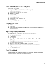
..., refer to the Desktop Board D850EMD2 or D850EMV2 link on page 21. Intel Desktop Boards D850EMD2 and D850EMV2 Product Guide Main Memory The desktop boards have four 2.5 V memory module sockets that support these features: • Integrated dual Direct Rambus technology memory channel • Support for 128 MB to 2 GB main system memory • Auto-detection of 32 RDRAM devices per channel • 128 MB (minimum) to 2 GB (maximum) onboard capacity utilizing 128/144 Mbit or...
..., refer to the Desktop Board D850EMD2 or D850EMV2 link on page 21. Intel Desktop Boards D850EMD2 and D850EMV2 Product Guide Main Memory The desktop boards have four 2.5 V memory module sockets that support these features: • Integrated dual Direct Rambus technology memory channel • Support for 128 MB to 2 GB main system memory • Auto-detection of 32 RDRAM devices per channel • 128 MB (minimum) to 2 GB (maximum) onboard capacity utilizing 128/144 Mbit or...
Product Guide
Page 13
... parallel port with Extended Capabilities Port (ECP) and Enhanced Parallel Port (EPP) support • Serial IRQ interface compatible with serialized IRQ support for PCI systems • PS/2 mouse and keyboard interfaces • Interface for one 1.2 MB, 1.44 MB, or 2.88 MB diskette drive • Intelligent power management, including a programmable wake up event interface • PCI power management support • Two fan tachometer inputs Real-Time Clock The desktop boards have...
... parallel port with Extended Capabilities Port (ECP) and Enhanced Parallel Port (EPP) support • Serial IRQ interface compatible with serialized IRQ support for PCI systems • PS/2 mouse and keyboard interfaces • Interface for one 1.2 MB, 1.44 MB, or 2.88 MB diskette drive • Intelligent power management, including a programmable wake up event interface • PCI power management support • Two fan tachometer inputs Real-Time Clock The desktop boards have...
Product Guide
Page 15
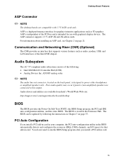
... The audio line out connector, located on the back panel, is a high-performance interface for graphics-intensive applications such as audio, modem, USB, and LAN interfaces of the Intel 850E chipset. The AGP connector supports 1.5 V AGP 4X and 2X add-in card. 15 Poor audio quality may occur if passive (non-amplified) speakers are connected to run the BIOS Setup program after you install a PCI add-in card in your computer, the PCI auto-configuration utility...
... The audio line out connector, located on the back panel, is a high-performance interface for graphics-intensive applications such as audio, modem, USB, and LAN interfaces of the Intel 850E chipset. The AGP connector supports 1.5 V AGP 4X and 2X add-in card. 15 Poor audio quality may occur if passive (non-amplified) speakers are connected to run the BIOS Setup program after you install a PCI add-in card in your computer, the PCI auto-configuration utility...
Product Guide
Page 16
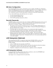
... the password prompt of Setup gives the user restricted access to run the BIOS Setup program after installing an IDE device. If both the supervisor and user passwords are set, you can override the auto-configuration options by specifying manual configuration in the BIOS Setup program. You do not need to Setup. • If both passwords are set , pressing at : http://support.intel.com/support/motherboards/desktop 16 Intel Desktop Boards D850EMD2 and D850EMV2 Product Guide IDE Auto Configuration If you install an IDE device (such as a hard drive...
... the password prompt of Setup gives the user restricted access to run the BIOS Setup program after installing an IDE device. If both the supervisor and user passwords are set, you can override the auto-configuration options by specifying manual configuration in the BIOS Setup program. You do not need to Setup. • If both passwords are set , pressing at : http://support.intel.com/support/motherboards/desktop 16 Intel Desktop Boards D850EMD2 and D850EMV2 Product Guide IDE Auto Configuration If you install an IDE device (such as a hard drive...

Product Guide
Page 18
... memory. Actual measurements may lose register settings stored in Table 4. Instantly Available technology enables the desktop board to enter the ACPI S3 (Suspend-to support multiple wake events from the PCI and/or USB buses exceeds power supply capacity, the desktop board may vary. 18 CR7F1 OM13620 Figure 3. This includes the memory modules and PCI bus connectors even when the computer appears to the system. If the system has a dual-colored power LED...
... memory. Actual measurements may lose register settings stored in Table 4. Instantly Available technology enables the desktop board to enter the ACPI S3 (Suspend-to support multiple wake events from the PCI and/or USB buses exceeds power supply capacity, the desktop board may vary. 18 CR7F1 OM13620 Figure 3. This includes the memory modules and PCI bus connectors even when the computer appears to the system. If the system has a dual-colored power LED...
Product Guide
Page 30
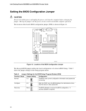
... shown in BIOS Setup. The location of the BIOS Configuration Jumper The three-pin BIOS jumper enables the board configuration to be done in Figure 14. 1 3 J9H2 OM13627 Figure 14. Table 5. Use this menu to recover the BIOS configuration. The BIOS attempts to clear passwords. Location of the board's BIOS configuration jumper (J9H2) is required. 30 After the POST runs, the BIOS displays the maintenance menu. Moving the jumper with the power on may result in unreliable computer operation. Intel Desktop Boards D850EMD2...
... shown in BIOS Setup. The location of the BIOS Configuration Jumper The three-pin BIOS jumper enables the board configuration to be done in Figure 14. 1 3 J9H2 OM13627 Figure 14. Table 5. Use this menu to recover the BIOS configuration. The BIOS attempts to clear passwords. Location of the board's BIOS configuration jumper (J9H2) is required. 30 After the POST runs, the BIOS displays the maintenance menu. Moving the jumper with the power on may result in unreliable computer operation. Intel Desktop Boards D850EMD2...
Product Guide
Page 36
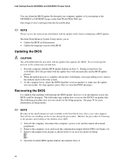
... procedure uses recovery mode for the Setup program. Insert the bootable BIOS update diskette into diskette drive A. 36 The Intel Flash Memory Update Utility allows you to remove the diskette and to reboot the system. 3. Boot the computer with the BIOS update diskette in flash memory • Update the language section of code available in the boot block area, there is complete, the monitor will automatically run the BIOS update process. 2. When the update process...
... procedure uses recovery mode for the Setup program. Insert the bootable BIOS update diskette into diskette drive A. 36 The Intel Flash Memory Update Utility allows you to remove the diskette and to reboot the system. 3. Boot the computer with the BIOS update diskette in flash memory • Update the language section of code available in the boot block area, there is complete, the monitor will automatically run the BIOS update process. 2. When the update process...

Product Guide
Page 39
... BIOS Setup program menu bar. For the latest BIOS settings, refer to the settings, update this record. ✏ NOTE The Setup menus described in some of the Setup menu screens. Table 6. The Setup screen menu bar is accessed by pressing the key after the Power-On Self-Test (POST) memory test begins and before the operating system boot begins. ✏ NOTE The BIOS Setup menus described in this section apply to the desktop boards...
... BIOS Setup program menu bar. For the latest BIOS settings, refer to the settings, update this record. ✏ NOTE The Setup menus described in some of the Setup menu screens. Table 6. The Setup screen menu bar is accessed by pressing the key after the Power-On Self-Test (POST) memory test begins and before the operating system boot begins. ✏ NOTE The BIOS Setup menus described in this section apply to the desktop boards...

Product Guide
Page 41
... video memory cache mode. This setting identifies the video memory range as "Extended Menu: Used." Well suited for applications not supporting Write Combining. 41 If selected here, will also display in the Advanced Menu as uncacheable by the processor. Memory writes are written to set system control and video memory cache mode. Extended Configuration Submenu Feature Options Description Extended Configuration Video Memory Cache Mode • Default (default) • User-Defined • USWC • UC (default) User-Defined allows setting memory control and video memory...
... video memory cache mode. This setting identifies the video memory range as "Extended Menu: Used." Well suited for applications not supporting Write Combining. 41 If selected here, will also display in the Advanced Menu as uncacheable by the processor. Memory writes are written to set system control and video memory cache mode. Extended Configuration Submenu Feature Options Description Extended Configuration Video Memory Cache Mode • Default (default) • User-Defined • USWC • UC (default) User-Defined allows setting memory control and video memory...
Product Guide
Page 47
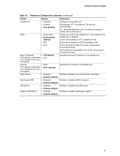
... Device • Disabled • Enabled (default) Legacy USB Support • Disabled • Enabled (default) Description Configures the parallel port. Enables or disables USB 2.0 support. Enables or disables the LAN device. Enables or disables USB legacy support. 47 Not available if the parallel port is Enhanced Capabilities Port mode, a high-speed bi-directional mode. Selects the mode for the parallel port. Auto assigns LPT1 the address 378h and the interrupt IRQ7. Output Only operates in PS/2-compatible mode. Enables or disables the onboard audio subsystem. Using...
... Device • Disabled • Enabled (default) Legacy USB Support • Disabled • Enabled (default) Description Configures the parallel port. Enables or disables USB 2.0 support. Enables or disables the LAN device. Enables or disables USB legacy support. 47 Not available if the parallel port is Enhanced Capabilities Port mode, a high-speed bi-directional mode. Selects the mode for the parallel port. Auto assigns LPT1 the address 378h and the interrupt IRQ7. Output Only operates in PS/2-compatible mode. Enables or disables the onboard audio subsystem. Using...
Product Guide
Page 49
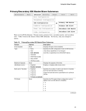
... Feature Drive Installed Type Maximum Capacity LBA Mode Control Multi-sector Transfers PIO Mode Options Description None Displays the type of drive installed. • None Specifies the IDE configuration mode for IDE devices. • User User allows capabilities to memory. Using the Setup Program Primary/Secondary IDE Master/Slave Submenus Maintenance Main Advanced Security Boot Configuration Power Boot Exit Peripheral Configuration IDE Configuration Diskette Configuration ➜ Primary IDE Master Primary IDE Slave Event Log Configuration Secondary IDE Master Video...
... Feature Drive Installed Type Maximum Capacity LBA Mode Control Multi-sector Transfers PIO Mode Options Description None Displays the type of drive installed. • None Specifies the IDE configuration mode for IDE devices. • User User allows capabilities to memory. Using the Setup Program Primary/Secondary IDE Master/Slave Submenus Maintenance Main Advanced Security Boot Configuration Power Boot Exit Peripheral Configuration IDE Configuration Diskette Configuration ➜ Primary IDE Master Primary IDE Slave Event Log Configuration Secondary IDE Master Video...
Product Guide
Page 50
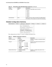
... and physical size of cable connected to configure the diskette drive. Diskette Configuration Submenu Maintenance Main Advanced Security Power PCI Configuration Boot Configuration Peripheral Configuration IDE Configuration Diskette Configuration Event Log Configuration Video Configuration This submenu shown in Table 17 is used to the IDE interface: 40-conductor or 80-conductor (for Ultra ATA-100 devices). Diskette Configuration Submenu Feature Diskette Controller Floppy A Diskette Write-Protect Options • Disabled • Enabled (default) • Not Installed •...
... and physical size of cable connected to configure the diskette drive. Diskette Configuration Submenu Maintenance Main Advanced Security Power PCI Configuration Boot Configuration Peripheral Configuration IDE Configuration Diskette Configuration Event Log Configuration Video Configuration This submenu shown in Table 17 is used to the IDE interface: 40-conductor or 80-conductor (for Ultra ATA-100 devices). Diskette Configuration Submenu Feature Diskette Controller Floppy A Diskette Write-Protect Options • Disabled • Enabled (default) • Not Installed •...
Product Guide
Page 54
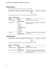
... • 120 Minutes Hard Drive • Disabled • Enabled (default) Description Enables or disables the APM feature. Specifies the amount of time before the computer enters APM standby mode. ACPI Submenu Maintenance Main Advanced Security Power APM ACPI Boot The submenu represented in Table 22 shows the setting options for hard disks during APM standby mode. In ACPI soft-off mode only, determines how the system responds to a LAN wake up event when...
... • 120 Minutes Hard Drive • Disabled • Enabled (default) Description Enables or disables the APM feature. Specifies the amount of time before the computer enters APM standby mode. ACPI Submenu Maintenance Main Advanced Security Power APM ACPI Boot The submenu represented in Table 22 shows the setting options for hard disks during APM standby mode. In ACPI soft-off mode only, determines how the system responds to a LAN wake up event when...
Product Guide
Page 55
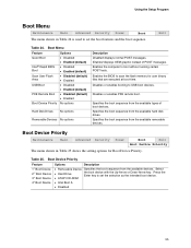
... Enter key to set the selection as the intended boot device. • ATAPI CD-ROM • Intel Boot A • Disabled 55 Table 25. Specifies the boot sequence from the available devices. Using the Setup Program Boot Menu Maintenance Main Advanced Security Power Boot The menu shown in Table 25 shows the setting options for user binary files that are executed at boot time. Boot Menu Feature Quiet Boot Intel® Rapid BIOS Boot Scan User Flash Area USB Boot PXE Remote Boot Boot Device Priority Options • Disabled • Enabled (default...
... Enter key to set the selection as the intended boot device. • ATAPI CD-ROM • Intel Boot A • Disabled 55 Table 25. Specifies the boot sequence from the available devices. Using the Setup Program Boot Menu Maintenance Main Advanced Security Power Boot The menu shown in Table 25 shows the setting options for user binary files that are executed at boot time. Boot Menu Feature Quiet Boot Intel® Rapid BIOS Boot Scan User Flash Area USB Boot PXE Remote Boot Boot Device Priority Options • Disabled • Enabled (default...
Product Guide
Page 70
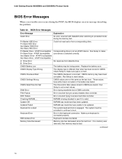
... updated. BIOS Error Messages Error Message Explanation GA20 Error An error occurred with GateA20 when switching to boot. CMOS Battery Low The battery may be unlocked to continue to protected mode during the POST, the BIOS displays an error message describing the problem. These values have been corrupted. Update OK! Keyboard Error Error in CMOS. KB/Interface Error Keyboard interface test failed. continued 70 Intel Desktop Boards D850EMD2 and D850EMV2 Product Guide BIOS Error Messages When a recoverable error occurs during the memory...
... updated. BIOS Error Messages Error Message Explanation GA20 Error An error occurred with GateA20 when switching to boot. CMOS Battery Low The battery may be unlocked to continue to protected mode during the POST, the BIOS displays an error message describing the problem. These values have been corrupted. Update OK! Keyboard Error Error in CMOS. KB/Interface Error Keyboard interface test failed. continued 70 Intel Desktop Boards D850EMD2 and D850EMV2 Product Guide BIOS Error Messages When a recoverable error occurs during the memory...


