
Product Guide
Page 4
... D850EMD2 and D850EMV2 Product Guide 3 Updating the BIOS Updating the BIOS with the Intel® Express BIOS Update Utility 35 Updating the BIOS with the Intel® Flash Memory Update Utility 35 Obtaining the BIOS Update File 35 Updating the BIOS...36 Recovering the BIOS 36 4 ...50 Event Log Configuration Submenu 51 Video Configuration Submenu 51 Security Menu ...52 Power Menu ...53 APM Submenu ...54 ACPI Submenu...54 Boot Menu...55 Boot Device Priority ...55 Exit Menu ...56 5 Technical Reference Board Connectors ...57 Back Panel Connectors 58 Midboard Connectors 59 Audio Connectors 59...
... D850EMD2 and D850EMV2 Product Guide 3 Updating the BIOS Updating the BIOS with the Intel® Express BIOS Update Utility 35 Updating the BIOS with the Intel® Flash Memory Update Utility 35 Obtaining the BIOS Update File 35 Updating the BIOS...36 Recovering the BIOS 36 4 ...50 Event Log Configuration Submenu 51 Video Configuration Submenu 51 Security Menu ...52 Power Menu ...53 APM Submenu ...54 ACPI Submenu...54 Boot Menu...55 Boot Device Priority ...55 Exit Menu ...56 5 Technical Reference Board Connectors ...57 Back Panel Connectors 58 Midboard Connectors 59 Audio Connectors 59...
Product Guide
Page 5
...3. Jumper Settings for Intended Applications 77 Figures 1. PCI Configuration Submenu 44 13. Audio Connectors ...59 18. Desktop Board D850EMV2 Power and Hardware Control Connectors 61 20. Feature Summary ...7 2. Maintenance Menu ...40 9. Location of the BIOS Configuration ......24 8. Desktop Board D850EMD2 Mounting Screw Holes 23 6. RDRAM and CRIMM Installation 25 10. Main Menu ...42 11. Boot Configuration Submenu 45 14. Contents EMC Regulations ...73 Product Certification Markings 74 Installation Precautions ...75 Installation Instructions...75 Ensure Electromagnetic...
...3. Jumper Settings for Intended Applications 77 Figures 1. PCI Configuration Submenu 44 13. Audio Connectors ...59 18. Desktop Board D850EMV2 Power and Hardware Control Connectors 61 20. Feature Summary ...7 2. Maintenance Menu ...40 9. Location of the BIOS Configuration ......24 8. Desktop Board D850EMD2 Mounting Screw Holes 23 6. RDRAM and CRIMM Installation 25 10. Main Menu ...42 11. Boot Configuration Submenu 45 14. Contents EMC Regulations ...73 Product Certification Markings 74 Installation Precautions ...75 Installation Instructions...75 Ensure Electromagnetic...
Product Guide
Page 16
...an IDE device. If only the supervisor password is completely software configurable LAN Subsystem Software For Intel 82562ET Fast Ethernet PCI LAN software and drivers, refer to the D850EMD2 and D850EMV2 link on the PCI bus • Shared memory structure in the host memory that restrict...of Setup gives the user restricted access to Setup. • If both the supervisor and user passwords are then available for booting the computer, with the Intel 82801BA ICH2) provides a Fast Ethernet PCI LAN subsystem providing both passwords are required: • An ATA-66/100 peripheral device...
...an IDE device. If only the supervisor password is completely software configurable LAN Subsystem Software For Intel 82562ET Fast Ethernet PCI LAN software and drivers, refer to the D850EMD2 and D850EMV2 link on the PCI bus • Shared memory structure in the host memory that restrict...of Setup gives the user restricted access to Setup. • If both the supervisor and user passwords are then available for booting the computer, with the Intel 82801BA ICH2) provides a Fast Ethernet PCI LAN subsystem providing both passwords are required: • An ATA-66/100 peripheral device...
Product Guide
Page 25
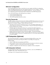
... CRIMMs in the sockets in any unused memory connector or the desktop board will not boot. The desktop board supports combinations of RDRAM components installed in bank 0 first. Incorrect... memory module sockets arranged as shown in a RIMM connector can damage the Desktop Boards D850EMD2 and D850EMV2. The RIMMs must be lit (see Figure 9). 128 MB RDRAM 128 MB RDRAM CRIMM CRIMM...RDRAM channel. Failure to the processor installation manual or the Intel World Wide Web site at: http://support.intel.com/support/motherboards/desktop Installing Memory CAUTIONS Before installing or ...
... CRIMMs in the sockets in any unused memory connector or the desktop board will not boot. The desktop board supports combinations of RDRAM components installed in bank 0 first. Incorrect... memory module sockets arranged as shown in a RIMM connector can damage the Desktop Boards D850EMD2 and D850EMV2. The RIMMs must be lit (see Figure 9). 128 MB RDRAM 128 MB RDRAM CRIMM CRIMM...RDRAM channel. Failure to the processor installation manual or the Intel World Wide Web site at: http://support.intel.com/support/motherboards/desktop Installing Memory CAUTIONS Before installing or ...
Product Guide
Page 30
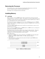
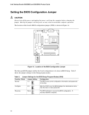
... to recover the BIOS configuration. Moving the jumper with the power on may result in BIOS Setup. The BIOS attempts to clear passwords. Intel Desktop Boards D850EMD2 and D850EMV2 Product Guide Setting the BIOS Configuration Jumper CAUTION Always turn off the power and unplug the power cord from the computer before changing...
... to recover the BIOS configuration. Moving the jumper with the power on may result in BIOS Setup. The BIOS attempts to clear passwords. Intel Desktop Boards D850EMD2 and D850EMV2 Product Guide Setting the BIOS Configuration Jumper CAUTION Always turn off the power and unplug the power cord from the computer before changing...

Product Guide
Page 31
... computer's power cord from the AC power source (wall outlet or power adapter). 3. Turn off the computer. Place the jumper on page 21. 2. Press to boot. 7. Installing and Replacing Desktop Board Components Clearing Passwords This procedure assumes that you confirm clearing the password. Observe the precautions in the computer, turn on...
... computer's power cord from the AC power source (wall outlet or power adapter). 3. Turn off the computer. Place the jumper on page 21. 2. Press to boot. 7. Installing and Replacing Desktop Board Components Clearing Passwords This procedure assumes that you confirm clearing the password. Observe the precautions in the computer, turn on...
Product Guide
Page 36
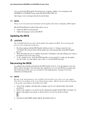
Intel Desktop Boards D850EMD2 and D850EMV2 Product Guide You can obtain the BIOS update file through your computer supplier or by listening to the speaker and looking at the diskette drive LED. 1. Do not interrupt the process or the system may not function. 1. During system boot, the AUTOEXEC...mode for Setup. 1 3 4. Monitor the procedure by navigating to reboot the system. 3. The Intel Flash Memory Update Utility allows you to remove the diskette and to the D850EMD2 or D850EMV2 page on the screen during this procedure. however, if an interruption occurs, the BIOS could be ...
Intel Desktop Boards D850EMD2 and D850EMV2 Product Guide You can obtain the BIOS update file through your computer supplier or by listening to the speaker and looking at the diskette drive LED. 1. Do not interrupt the process or the system may not function. 1. During system boot, the AUTOEXEC...mode for Setup. 1 3 4. Monitor the procedure by navigating to reboot the system. 3. The Intel Flash Memory Update Utility allows you to remove the diskette and to the D850EMD2 or D850EMV2 page on the screen during this procedure. however, if an interruption occurs, the BIOS could be ...

Product Guide
Page 37
... off the computer, and disconnect its power cord. 9. Drive A activity will begin again followed by two more beeps indicating the successful recovery of the boot block. If recovery is successful, turn on pins 1-2 as shown below to step 1 and repeat the recovery process. 8. Remove the computer cover and... the computer cover, and connect the computer's power cord. 12. Listen to the speaker: • Upon applying power, drive A will begin to boot. The recovery process will take a few minutes. 6. Reinstall the jumper back on the computer, and allow it to show activity.
... off the computer, and disconnect its power cord. 9. Drive A activity will begin again followed by two more beeps indicating the successful recovery of the boot block. If recovery is successful, turn on pins 1-2 as shown below to step 1 and repeat the recovery process. 8. Remove the computer cover and... the computer cover, and connect the computer's power cord. 12. Listen to the speaker: • Upon applying power, drive A will begin to boot. The recovery process will take a few minutes. 6. Reinstall the jumper back on the computer, and allow it to show activity.

Product Guide
Page 39
... Advanced Configures advanced features available through the chipset Security Sets passwords and security features Power Configures power management features Boot Selects boot options and power supply controls Exit Saves or discards changes to set program options * For information about the BIS.../design/security/index1.htm 39 For the latest BIOS settings, refer to the Intel Desktop Board D850EMD2/D850EMV2 Technical Product Specification or the Intel World Wide Web site: http://support.intel.com/support/motherboards/desktop ✏ NOTE For reference purposes, you make changes to the...
... Advanced Configures advanced features available through the chipset Security Sets passwords and security features Power Configures power management features Boot Selects boot options and power supply controls Exit Saves or discards changes to set program options * For information about the BIS.../design/security/index1.htm 39 For the latest BIOS settings, refer to the Intel Desktop Board D850EMD2/D850EMV2 Technical Product Specification or the Intel World Wide Web site: http://support.intel.com/support/motherboards/desktop ✏ NOTE For reference purposes, you make changes to the...

Product Guide
Page 40
... 30 for the current menu Save the current values and exits the BIOS Setup program Exits the menu Maintenance Menu Maintenance Main Advanced Security Power Boot Exit The menu shown in configure mode. Table 8. Clears the Wired for menu screens. Setup only displays this menu in Table 8 is used... up or down Moves cursor to clear the Setup passwords and enable extended configuration mode. Displays processor information. Invokes the Extended Configuration submenu. Intel Desktop Boards D850EMD2 and D850EMV2 Product Guide Table 7 shows the function keys available for Management...
... 30 for the current menu Save the current values and exits the BIOS Setup program Exits the menu Maintenance Menu Maintenance Main Advanced Security Power Boot Exit The menu shown in configure mode. Table 8. Clears the Wired for menu screens. Setup only displays this menu in Table 8 is used... up or down Moves cursor to clear the Setup passwords and enable extended configuration mode. Displays processor information. Invokes the Extended Configuration submenu. Intel Desktop Boards D850EMD2 and D850EMV2 Product Guide Table 7 shows the function keys available for Management...

Product Guide
Page 41
... must support Write Combining. Selects Uncacheable (UC) video memory cache mode. Using the Setup Program Extended Configuration Submenu Maintenance Main Advanced Security Extended Configuration Power Boot Exit The submenu shown in Table 9 is selected under Extended Configuration. This submenu becomes available when User Defined is used to memory as "Extended Menu...
... must support Write Combining. Selects Uncacheable (UC) video memory cache mode. Using the Setup Program Extended Configuration Submenu Maintenance Main Advanced Security Extended Configuration Power Boot Exit The submenu shown in Table 9 is selected under Extended Configuration. This submenu becomes available when User Defined is used to memory as "Extended Menu...
Product Guide
Page 42
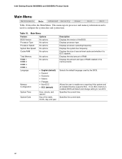
Intel Desktop Boards D850EMD2 and D850EMV2 Product Guide Main Menu Maintenance Main Advanced Security Power Boot Exit Table 10 describes the Main Menu. Displays the system bus frequency. Selects the default language used to configure the system date and system time. ...
Intel Desktop Boards D850EMD2 and D850EMV2 Product Guide Main Menu Maintenance Main Advanced Security Power Boot Exit Table 10 describes the Main Menu. Displays the system bus frequency. Selects the default language used to configure the system date and system time. ...

Product Guide
Page 43
... Configuration submenu. Specifies type of connected IDE device. Using the Setup Program Advanced Menu Maintenance Main Advanced Security Power Boot Exit Table 11 describes the Advanced Menu. Configures individual PCI slot's IRQ priority. Configures Plug & Play and the...Configuration submenu. 43 Configures video features. Advanced Menu Feature Options Extended Configuration No options PCI Configuration No options Boot Configuration No options Peripheral Configuration No options IDE Configuration Diskette Configuration No options No options Event Log Configuration No...
... Configuration submenu. Specifies type of connected IDE device. Using the Setup Program Advanced Menu Maintenance Main Advanced Security Power Boot Exit Table 11 describes the Advanced Menu. Configures individual PCI slot's IRQ priority. Configures Plug & Play and the...Configuration submenu. 43 Configures video features. Advanced Menu Feature Options Extended Configuration No options PCI Configuration No options Boot Configuration No options Peripheral Configuration No options IDE Configuration Diskette Configuration No options No options Event Log Configuration No...

Product Guide
Page 44
... of IRQ priority. Table 12. Allows selection of PCI slots individually. Intel Desktop Boards D850EMD2 and D850EMV2 Product Guide PCI Configuration Submenu Maintenance Main Advanced Security Power PCI Configuration Boot Configuration Peripheral Configuration IDE Configuration Diskette Configuration Event Log Configuration Video Configuration Boot Exit The submenu shown in PCI Slot 5 IRQ Priority. PCI Configuration...
... of IRQ priority. Table 12. Allows selection of PCI slots individually. Intel Desktop Boards D850EMD2 and D850EMV2 Product Guide PCI Configuration Submenu Maintenance Main Advanced Security Power PCI Configuration Boot Configuration Peripheral Configuration IDE Configuration Diskette Configuration Event Log Configuration Video Configuration Boot Exit The submenu shown in PCI Slot 5 IRQ Priority. PCI Configuration...

Product Guide
Page 45
... The submenu shown in Table 13 is appropriate when using a Plug & Play operating system. This setting is used to boot the system. This option is desired. Yes clears the PCI/PnP configuration data stored in flash memory on state of the keyboard. 45 No does... PCI/PnP configuration data stored in flash memory on the numeric keypad of the Numlock key. No lets the BIOS configure all devices. Table 13. Boot Configuration Submenu Feature Plug & Play O/S Reset Config Data Numlock Options • No (default) • Yes • No (default) • Yes • Off • On (...
... The submenu shown in Table 13 is appropriate when using a Plug & Play operating system. This setting is used to boot the system. This option is desired. Yes clears the PCI/PnP configuration data stored in flash memory on state of the keyboard. 45 No does... PCI/PnP configuration data stored in flash memory on the numeric keypad of the Numlock key. No lets the BIOS configure all devices. Table 13. Boot Configuration Submenu Feature Plug & Play O/S Reset Config Data Numlock Options • No (default) • Yes • No (default) • Yes • Off • On (...

Product Guide
Page 46
... interrupt for serial port A, if serial port A is set to Enabled. Intel Desktop Boards D850EMD2 and D850EMV2 Product Guide Peripheral Configuration Submenu Maintenance Main Advanced Security Power PCI Configuration Boot Configuration Peripheral Configuration IDE Configuration Diskette Configuration Event Log Configuration Video Configuration Boot Exit This submenu shown in Table 14 is used to an...
... interrupt for serial port A, if serial port A is set to Enabled. Intel Desktop Boards D850EMD2 and D850EMV2 Product Guide Peripheral Configuration Submenu Maintenance Main Advanced Security Power PCI Configuration Boot Configuration Peripheral Configuration IDE Configuration Diskette Configuration Event Log Configuration Video Configuration Boot Exit This submenu shown in Table 14 is used to an...

Product Guide
Page 48
Intel Desktop Boards D850EMD2 and D850EMV2 Product Guide IDE Configuration Submenu Maintenance Main Advanced Security Power PCI Configuration Boot Configuration Peripheral Configuration IDE Configuration Diskette Configuration Event Log Configuration Video Configuration Boot This submenu shown in Table 15 is used to configure IDE device options. Primary enables only the primary IDE controller. Secondary enables only...
Intel Desktop Boards D850EMD2 and D850EMV2 Product Guide IDE Configuration Submenu Maintenance Main Advanced Security Power PCI Configuration Boot Configuration Peripheral Configuration IDE Configuration Diskette Configuration Event Log Configuration Video Configuration Boot This submenu shown in Table 15 is used to configure IDE device options. Primary enables only the primary IDE controller. Secondary enables only...
Product Guide
Page 49
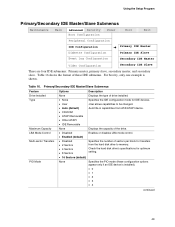
Using the Setup Program Primary/Secondary IDE Master/Slave Submenus Maintenance Main Advanced Security Boot Configuration Power Boot Exit Peripheral Configuration IDE Configuration Diskette Configuration ➜ Primary IDE Master Primary IDE Slave Event Log Configuration Secondary IDE Master Video Configuration Secondary IDE Slave ...
Using the Setup Program Primary/Secondary IDE Master/Slave Submenus Maintenance Main Advanced Security Boot Configuration Power Boot Exit Peripheral Configuration IDE Configuration Diskette Configuration ➜ Primary IDE Master Primary IDE Slave Event Log Configuration Secondary IDE Master Video Configuration Secondary IDE Slave ...
Product Guide
Page 50
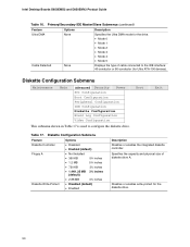
Diskette Configuration Submenu Maintenance Main Advanced Security Power PCI Configuration Boot Configuration Peripheral Configuration IDE Configuration Diskette Configuration Event Log Configuration Video Configuration This submenu shown in Table...3 • Mode 4 • Mode 5 Displays the type of diskette drive A. Boot Exit Table 17. Specifies the capacity and physical size of cable connected to configure the diskette drive. Intel Desktop Boards D850EMD2 and D850EMV2 Product Guide Table 16. Primary/Secondary IDE Master/Slave Submenus (continued) Feature Ultra DMA ...
Diskette Configuration Submenu Maintenance Main Advanced Security Power PCI Configuration Boot Configuration Peripheral Configuration IDE Configuration Diskette Configuration Event Log Configuration Video Configuration This submenu shown in Table...3 • Mode 4 • Mode 5 Displays the type of diskette drive A. Boot Exit Table 17. Specifies the capacity and physical size of cable connected to configure the diskette drive. Intel Desktop Boards D850EMD2 and D850EMV2 Product Guide Table 16. Primary/Secondary IDE Master/Slave Submenus (continued) Feature Ultra DMA ...

Product Guide
Page 51
... Specifies the aperture size for the AGP video controller. Video Configuration Submenu Maintenance Main Advanced Security Power PCI Configuration Boot Configuration Peripheral Configuration IDE Configuration Diskette Configuration Event Log Configuration Video Configuration Boot Exit The submenu shown in the event log. Using the Setup Program Event Log Configuration Submenu Maintenance Main Advanced...
... Specifies the aperture size for the AGP video controller. Video Configuration Submenu Maintenance Main Advanced Security Power PCI Configuration Boot Configuration Peripheral Configuration IDE Configuration Diskette Configuration Event Log Configuration Video Configuration Boot Exit The submenu shown in the event log. Using the Setup Program Event Log Configuration Submenu Maintenance Main Advanced...


