
Technical Product Specification
Page 8
... Options for Front Panel USB Connectors 63 17. Flex 6 Audio Subsystem Block Diagram 30 6. LAN Connector LED Locations 31 7. LAN Connector LED Locations 32 8. Thermal Monitoring...34 9. Location of the Standby Power Indicator LED on the D848PMB Board 41 10. Audio Connectors ...53 12. Power and Hardware Control Connectors 55 13. Connection Diagram for Flex 6 Audio Subsystem 29 4. Feature Summary...12 2. Specifications ...17 4. Supported System Bus Frequency and Memory Speed Combinations 21 5. Supported Memory Configurations 22 6. LAN Connector LED States 33 8. Fan...
... Options for Front Panel USB Connectors 63 17. Flex 6 Audio Subsystem Block Diagram 30 6. LAN Connector LED Locations 31 7. LAN Connector LED Locations 32 8. Thermal Monitoring...34 9. Location of the Standby Power Indicator LED on the D848PMB Board 41 10. Audio Connectors ...53 12. Power and Hardware Control Connectors 55 13. Connection Diagram for Flex 6 Audio Subsystem 29 4. Feature Summary...12 2. Specifications ...17 4. Supported System Bus Frequency and Memory Speed Combinations 21 5. Supported Memory Configurations 22 6. LAN Connector LED States 33 8. Fan...
Technical Product Specification
Page 9
.... USB Configuration Submenu 101 61. Chipset Configuration Submenu 102 62. Power Menu ...107 66. ATAPI CD-ROM Drives Submenu 111 ix Processor Fan Connector 56 26. Chassis Intrusion Connector 57 29. Auxiliary Front Panel Power/Sleep/Message-Waiting LED Connector 61 32. States for a Two-Color Power LED 62 35. Front Panel Audio Connector/Jumper Block 65 36. Desktop Board D848PMB Environmental Specifications 72 41. Additional System Information Submenu 88 51. Boot Configuration Submenu 91 54. Hardware Monitoring Display 105 64. Boot Device Priority...
.... USB Configuration Submenu 101 61. Chipset Configuration Submenu 102 62. Power Menu ...107 66. ATAPI CD-ROM Drives Submenu 111 ix Processor Fan Connector 56 26. Chassis Intrusion Connector 57 29. Auxiliary Front Panel Power/Sleep/Message-Waiting LED Connector 61 32. States for a Two-Color Power LED 62 35. Front Panel Audio Connector/Jumper Block 65 36. Desktop Board D848PMB Environmental Specifications 72 41. Additional System Information Submenu 88 51. Boot Configuration Submenu 91 54. Hardware Monitoring Display 105 64. Boot Device Priority...
Technical Product Specification
Page 17
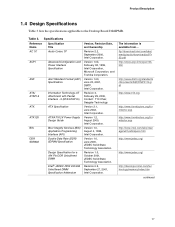
... 3, February 29, 2000, Contact: T13 Chair, Seagate Technology. Specifications Reference Name AC '97 ACPI ASF ATA/ ATAPI-5 ATX Specification Title Audio Codec '97 Advanced Configuration and Power Interface Specification Alert Standard Format (ASF) Specification Information Technology-AT Attachment with Packet Interface - 5 (ATA/ATAPI-5) ATX Specification Version, Revision Date, and Ownership Revision 2.2, September 2000, Intel Corporation. ATX12V ATX/ATX12V Power Supply Design Guide Version 1.2, August 2000, Intel Corporation. Revision 0.9, September 27, 2001...
... 3, February 29, 2000, Contact: T13 Chair, Seagate Technology. Specifications Reference Name AC '97 ACPI ASF ATA/ ATAPI-5 ATX Specification Title Audio Codec '97 Advanced Configuration and Power Interface Specification Alert Standard Format (ASF) Specification Information Technology-AT Attachment with Packet Interface - 5 (ATA/ATAPI-5) ATX Specification Version, Revision Date, and Ownership Revision 2.2, September 2000, Intel Corporation. ATX12V ATX/ATX12V Power Supply Design Guide Version 1.2, August 2000, Intel Corporation. Revision 0.9, September 27, 2001...
Technical Product Specification
Page 26
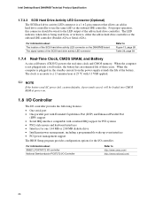
... add-in hard drive controller to use the same LED as the onboard IDE controller. Intel Desktop Board D848PMB Technical Product Specification 1.7.3.3 SCSI Hard Drive Activity LED Connector (Optional) The SCSI hard drive activity LED connector is not plugged into CMOS RAM at power-on the D848PMB board The signal names of the SCSI hard drive activity LED connector Refer to Figure 13, page 58 Table 29, page 59 1.7.4 Real-Time Clock, CMOS SRAM, and Battery A coin-cell battery (CR2032) powers the real-time clock and CMOS memory. The LED indicates...
... add-in hard drive controller to use the same LED as the onboard IDE controller. Intel Desktop Board D848PMB Technical Product Specification 1.7.3.3 SCSI Hard Drive Activity LED Connector (Optional) The SCSI hard drive activity LED connector is not plugged into CMOS RAM at power-on the D848PMB board The signal names of the SCSI hard drive activity LED connector Refer to Figure 13, page 58 Table 29, page 59 1.7.4 Real-Time Clock, CMOS SRAM, and Battery A coin-cell battery (CR2032) powers the real-time clock and CMOS memory. The LED indicates...
Technical Product Specification
Page 50
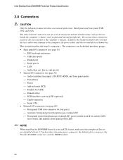
...front panel audio) Fans [three] Power Add-in boards (PCI) Parallel ATA IDE Diskette drive SCSI hard drive activity LED (optional) Chassis intrusion Serial ATA • External I/O connectors (see page 60) Front panel USB (two connector for four ports) Auxiliary front panel power/sleep/message-waiting LED Front panel (power/sleep/message-waiting LED, power switch, hard drive activity LED, reset switch, and auxiliary front panel power LED) ✏ NOTE When installing the D848PMB board in the load...
...front panel audio) Fans [three] Power Add-in boards (PCI) Parallel ATA IDE Diskette drive SCSI hard drive activity LED (optional) Chassis intrusion Serial ATA • External I/O connectors (see page 60) Front panel USB (two connector for four ports) Auxiliary front panel power/sleep/message-waiting LED Front panel (power/sleep/message-waiting LED, power switch, hard drive activity LED, reset switch, and auxiliary front panel power LED) ✏ NOTE When installing the D848PMB board in the load...
Technical Product Specification
Page 78
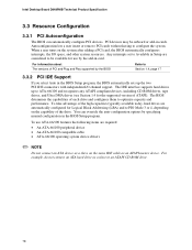
... 3.3.2 PCI IDE Support If you select Auto in the BIOS Setup program, the BIOS automatically sets up to ATA-66/100 and recognizes any ATAPI compliant devices, including CD-ROM drives, tape drives, and Ultra DMA drives (see Section 1.4 for use ATA-66/100 features the following items are considered to optimize capacity and performance. Intel Desktop Board D848PMB Technical Product Specification 3.3 Resource Configuration 3.3.1 PCI Autoconfiguration The BIOS can override the auto-configuration options by...
... 3.3.2 PCI IDE Support If you select Auto in the BIOS Setup program, the BIOS automatically sets up to ATA-66/100 and recognizes any ATAPI compliant devices, including CD-ROM drives, tape drives, and Ultra DMA drives (see Section 1.4 for use ATA-66/100 features the following items are considered to optimize capacity and performance. Intel Desktop Board D848PMB Technical Product Specification 3.3 Resource Configuration 3.3.1 PCI Autoconfiguration The BIOS can override the auto-configuration options by...
Technical Product Specification
Page 85
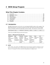
The menu bar is in configure mode. 85 BIOS Setup Program Menu Bar Maintenance Main Advanced Security Clears passwords and displays processor information Displays processor and memory configuration Configures advanced features available through the chipset Sets passwords and security features Power Boot Configures power management features and power supply controls Selects boot options Exit Saves or discards changes to view and change the BIOS settings for the computer. Table 46. Section 2.9.2 on page 65 tells how to put the Desktop Board in configure mode. 4 BIOS Setup ...
The menu bar is in configure mode. 85 BIOS Setup Program Menu Bar Maintenance Main Advanced Security Clears passwords and displays processor information Displays processor and memory configuration Configures advanced features available through the chipset Sets passwords and security features Power Boot Configures power management features and power supply controls Selects boot options Exit Saves or discards changes to view and change the BIOS settings for the computer. Table 46. Section 2.9.2 on page 65 tells how to put the Desktop Board in configure mode. 4 BIOS Setup ...
Technical Product Specification
Page 86
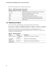
... 65 for configure mode setting information. Intel Desktop Board D848PMB Technical Product Specification Table 47 lists the function keys available for clearing Setup passwords and displaying processor information. BIOS Setup Program Function Keys BIOS Setup Program Function Key or or Description Selects a different menu screen (Moves the cursor left or right) Selects an item (Moves the cursor up or down) Selects a field (Not implemented) Executes command or selects the submenu Load the default configuration values for...
... 65 for configure mode setting information. Intel Desktop Board D848PMB Technical Product Specification Table 47 lists the function keys available for clearing Setup passwords and displaying processor information. BIOS Setup Program Function Keys BIOS Setup Program Function Key or or Description Selects a different menu screen (Moves the cursor left or right) Selects an item (Moves the cursor up or down) Selects a field (Not implemented) Executes command or selects the submenu Load the default configuration values for...
Technical Product Specification
Page 97
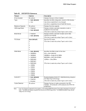
... ATAPI floppy drive. Auto = Auto-detected SWDMAn = Single Word DMAn MWDMAn = Multi Word DMAn UDMAn = Ultra DMAn (This item is read-only unless Type is set to User.) Enables/disables S.M.A.R.T. (Self-Monitoring, Analysis, and Reporting Technology). (This item is read-only unless Type is set to User.) Sets the PIO mode. (This item is read -only unless Type is set to User.) Displays the type of drive installed. Specifies the IDE configuration mode for the drive. User allows...
... ATAPI floppy drive. Auto = Auto-detected SWDMAn = Single Word DMAn MWDMAn = Multi Word DMAn UDMAn = Ultra DMAn (This item is read-only unless Type is set to User.) Enables/disables S.M.A.R.T. (Self-Monitoring, Analysis, and Reporting Technology). (This item is read-only unless Type is set to User.) Sets the PIO mode. (This item is read -only unless Type is set to User.) Displays the type of drive installed. Specifies the IDE configuration mode for the drive. User allows...
Technical Product Specification
Page 104
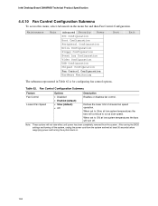
... the menu bar and then Fan Control Configuration. After saving the BIOS settings and turning off . Maintenance Main Advanced Security Power PCI Configuration Boot Configuration Peripheral Configuration Drive Configuration Floppy Configuration Event Log Configuration Video Configuration USB Configuration Chipset Configuration Fan Control Configuration Hardware Monitoring Boot Exit The submenu represented in Table 62 is for configuring fan control options. Intel Desktop Board D848PMB Technical Product Specification 4.4.10 Fan Control Configuration Submenu To access this menu, select...
... the menu bar and then Fan Control Configuration. After saving the BIOS settings and turning off . Maintenance Main Advanced Security Power PCI Configuration Boot Configuration Peripheral Configuration Drive Configuration Floppy Configuration Event Log Configuration Video Configuration USB Configuration Chipset Configuration Fan Control Configuration Hardware Monitoring Boot Exit The submenu represented in Table 62 is for configuring fan control options. Intel Desktop Board D848PMB Technical Product Specification 4.4.10 Fan Control Configuration Submenu To access this menu, select...
Technical Product Specification
Page 108
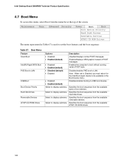
... to LAN. Note: When set the boot features and the boot sequence. Enabled displays OEM graphic instead of the screen. Maintenance Main Advanced Security Power Boot Exit Boot Device Priority Hard Disk Drives Removable Devices ATAPI CD-ROM Drives The menu represented in Table 67 is used to set to Enabled, you must reboot for the Intel Boot Agent device to be available in the Boot Device menu. Intel Desktop Board D848PMB Technical Product Specification 4.7 Boot Menu To access this menu, select Boot from the available ATAPI CD-ROM drives. 108 Disables/enables PXE boot...
... to LAN. Note: When set the boot features and the boot sequence. Enabled displays OEM graphic instead of the screen. Maintenance Main Advanced Security Power Boot Exit Boot Device Priority Hard Disk Drives Removable Devices ATAPI CD-ROM Drives The menu represented in Table 67 is used to set to Enabled, you must reboot for the Intel Boot Agent device to be available in the Boot Device menu. Intel Desktop Board D848PMB Technical Product Specification 4.7 Boot Menu To access this menu, select Boot from the available ATAPI CD-ROM drives. 108 Disables/enables PXE boot...
Technical Product Specification
Page 115
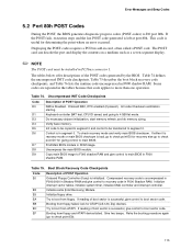
Displaying the POST-codes requires a PCI bus add-in ROM image. Init code Checksum verification starting. Verify base memory. Table 75. Compressed recovery code is in segment 0. Retry the booting procedure again (go to check point D7 for ATAPI (LS-120, Zip) devices. Onboard KBC, RTC enabled (if present). Keyboard controller BAT test, CPU ID saved, and going to I/O port 80h. Find Main BIOS module in card, often called a POST card. Copy main BIOS image to F000...
Displaying the POST-codes requires a PCI bus add-in ROM image. Init code Checksum verification starting. Verify base memory. Table 75. Compressed recovery code is in segment 0. Retry the booting procedure again (go to check point D7 for ATAPI (LS-120, Zip) devices. Onboard KBC, RTC enabled (if present). Keyboard controller BAT test, CPU ID saved, and going to I/O port 80h. Find Main BIOS module in card, often called a POST card. Copy main BIOS image to F000...
Technical Product Specification
Page 120
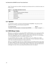
... fail. The BIOS also issues a beep code (one long tone followed by two short tones) during POST if the video configuration fails (a faulty video card or no card installed) or if an external ROM module does not properly checksum to initialize the video and writes the error in the upper left corner of the screen (using both monochrome and color adapters). 120 Intel Desktop Board D848PMB Technical Product Specification Table 79 describes...
... fail. The BIOS also issues a beep code (one long tone followed by two short tones) during POST if the video configuration fails (a faulty video card or no card installed) or if an external ROM module does not properly checksum to initialize the video and writes the error in the upper left corner of the screen (using both monochrome and color adapters). 120 Intel Desktop Board D848PMB Technical Product Specification Table 79 describes...
Product Guide
Page 13
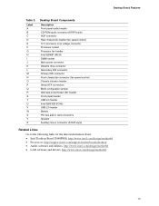
... Front panel audio header CD-ROM audio connector (ATAPI-style) AGP connector Rear chassis fan header (fan speed control) 12 V processor core voltage connector Processor socket Processor fan header Intel 82848P (MCH) DIMM socket Main power connector Diskette drive connector Secondary IDE connector Primary IDE connector Front chassis fan connector (fan speed control) Chassis intrusion header Serial ATA connectors BIOS configuration jumper Alternate power/sleep LED header Front panel header USB 2.0 header Intel 82801EB (ICH5) USB 2.0 header Battery PCI bus add-in card connectors Speaker Auxiliary...
... Front panel audio header CD-ROM audio connector (ATAPI-style) AGP connector Rear chassis fan header (fan speed control) 12 V processor core voltage connector Processor socket Processor fan header Intel 82848P (MCH) DIMM socket Main power connector Diskette drive connector Secondary IDE connector Primary IDE connector Front chassis fan connector (fan speed control) Chassis intrusion header Serial ATA connectors BIOS configuration jumper Alternate power/sleep LED header Front panel header USB 2.0 header Intel 82801EB (ICH5) USB 2.0 header Battery PCI bus add-in card connectors Speaker Auxiliary...
Product Guide
Page 19
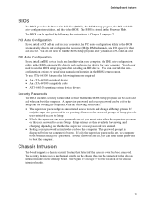
... user password was entered. • Setting a user password restricts who can be set , pressing at the password prompt of the chassis intrusion header. 19 Desktop Board Features BIOS The BIOS provides the Power-On Self-Test (POST), the BIOS Setup program, the PCI and IDE auto-configuration utilities, and the video BIOS. You do not need to run the BIOS Setup program after installing an IDE device. You do not need to run the BIOS Setup program after you install an IDE device (such as a hard drive...
... user password was entered. • Setting a user password restricts who can be set , pressing at the password prompt of the chassis intrusion header. 19 Desktop Board Features BIOS The BIOS provides the Power-On Self-Test (POST), the BIOS Setup program, the PCI and IDE auto-configuration utilities, and the video BIOS. You do not need to run the BIOS Setup program after installing an IDE device. You do not need to run the BIOS Setup program after you install an IDE device (such as a hard drive...
Product Guide
Page 51
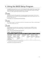
... The BIOS Setup menus described in this section apply to the Intel® Desktop Board D848PMB Technical Product Specification or the Intel World Wide Web site: http://support.intel.com/support/motherboards/desktop NOTE For reference purposes, you make changes to view and change the BIOS settings for hardware components Configures advanced features available through the chipset Sets passwords and security features Configures power management features Selects boot options and power supply controls Saves or discards changes to set program options...
... The BIOS Setup menus described in this section apply to the Intel® Desktop Board D848PMB Technical Product Specification or the Intel World Wide Web site: http://support.intel.com/support/motherboards/desktop NOTE For reference purposes, you make changes to view and change the BIOS settings for hardware components Configures advanced features available through the chipset Sets passwords and security features Configures power management features Selects boot options and power supply controls Saves or discards changes to set program options...
Product Guide
Page 54
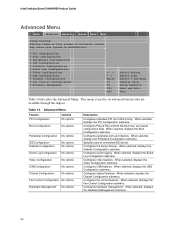
... Log Configuration ` Video Configuration ` USB Configuration ` Chipset Configuration ` Fan Control Configuration ` Hardware Management Enter F1 P9 F10 ESC Select Screen Select Item Select ` Sub-Menu General Help Setup Defaults Save and Exit Exit Table 14 describes the Advanced Menu. When selected, displays the PCI Configuration submenu. Configures Plug & Play and the Numlock key, and resets configuration data. When selected, displays the Peripheral Configuration submenu. Configures the floppy drive(s). Configures event logging. When selected, displays the Fan Control Configuration...
... Log Configuration ` Video Configuration ` USB Configuration ` Chipset Configuration ` Fan Control Configuration ` Hardware Management Enter F1 P9 F10 ESC Select Screen Select Item Select ` Sub-Menu General Help Setup Defaults Save and Exit Exit Table 14 describes the Advanced Menu. When selected, displays the PCI Configuration submenu. Configures Plug & Play and the Numlock key, and resets configuration data. When selected, displays the Peripheral Configuration submenu. Configures the floppy drive(s). Configures event logging. When selected, displays the Fan Control Configuration...
Product Guide
Page 66
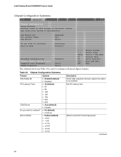
... to be enabled. Alters host and I/O clock frequencies. Intel Desktop Board D848PMB Product Guide Chipset Configuration Submenu Main Advanced Security Power Boot Exit Chipset Configuration Setup Warning: Setting items on this option to malfunction! Burn-In Mode [Continue] [Default] Extended Configuration Chipset Memory Timing Control Graphics Core Frequency SDRAM Frequency [Default] [Auto] [Auto] Enter F1 P9 F10 ESC Select Screen Select Item Select ` Sub-Menu General Help Setup Defaults Save and Exit Exit The submenu shown in Table 24 is used to continue...
... to be enabled. Alters host and I/O clock frequencies. Intel Desktop Board D848PMB Product Guide Chipset Configuration Submenu Main Advanced Security Power Boot Exit Chipset Configuration Setup Warning: Setting items on this option to malfunction! Burn-In Mode [Continue] [Default] Extended Configuration Chipset Memory Timing Control Graphics Core Frequency SDRAM Frequency [Default] [Auto] [Auto] Enter F1 P9 F10 ESC Select Screen Select Item Select ` Sub-Menu General Help Setup Defaults Save and Exit Exit The submenu shown in Table 24 is used to continue...
Product Guide
Page 70
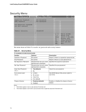
...set . 2. Intel Desktop Board D848PMB Product Guide Security Menu Main Advanced Security Power Boot Exit Supervisor Password : User Password : Not Installed Not Installed Set Supervisor Password Set User Password Chassis Intrusion [Disabled] Enter F1 P9 F10 ESC Select Screen Select Item Select ` Sub-Menu General Help Setup Defaults Save and Exit Exit The menu shown in Table 27 is a supervisor password set. alphanumeric characters. • Yes (default) Clears the user password. • No • Limited • No access Sets BIOS Setup Utility access rights for user...
...set . 2. Intel Desktop Board D848PMB Product Guide Security Menu Main Advanced Security Power Boot Exit Supervisor Password : User Password : Not Installed Not Installed Set Supervisor Password Set User Password Chassis Intrusion [Disabled] Enter F1 P9 F10 ESC Select Screen Select Item Select ` Sub-Menu General Help Setup Defaults Save and Exit Exit The menu shown in Table 27 is a supervisor password set. alphanumeric characters. • Yes (default) Clears the user password. • No • Limited • No access Sets BIOS Setup Utility access rights for user...
Product Guide
Page 73
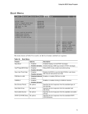
...-ROM drives. 73 No options Specifies the boot sequence from the available removable devices. Using the BIOS Setup Program Boot Menu Main Advanced Security Power Boot Exit Silent BOOT Intel ® Rapid BIOS Boot Scan User Flash Area PXE Boot to LAN USB Boot ` Boot Device Priority ` Hard Disk Drives ` Removable Devices ` ATAPI CD-ROM Drives [Enabled] [Enabled] [Enabled] [Disabled] [Enabled] Enter F1 P9 F10 ESC Select Screen Select Item Select ` Sub-Menu General Help Setup Defaults Save and Exit Exit The menu shown in Table 30 is used to USB boot devices. • Enabled (default...
...-ROM drives. 73 No options Specifies the boot sequence from the available removable devices. Using the BIOS Setup Program Boot Menu Main Advanced Security Power Boot Exit Silent BOOT Intel ® Rapid BIOS Boot Scan User Flash Area PXE Boot to LAN USB Boot ` Boot Device Priority ` Hard Disk Drives ` Removable Devices ` ATAPI CD-ROM Drives [Enabled] [Enabled] [Enabled] [Disabled] [Enabled] Enter F1 P9 F10 ESC Select Screen Select Item Select ` Sub-Menu General Help Setup Defaults Save and Exit Exit The menu shown in Table 30 is used to USB boot devices. • Enabled (default...


