Product Guide
Page 4
Intel Desktop Boards D845GERG2 and D845GEBV2 Product Guide Installing a Processor 24 Installing the Processor Fan Heat Sink 24 Connecting the Processor Fan Heat Sink Cable 25 Removing the Processor ... or ADD Card 28 Removing the AGP or ADD Card 28 Connecting the IDE Cable 29 Connecting Front Panel Headers 30 Connecting the Front Panel Header 31 Installing a Front Panel Audio Solution 31 Installing a Front Panel USB Solution 32 Connecting Fans and Power Cables 33 Connecting Fans ...33 Connecting Power Cables 33 Setting the...
Intel Desktop Boards D845GERG2 and D845GEBV2 Product Guide Installing a Processor 24 Installing the Processor Fan Heat Sink 24 Connecting the Processor Fan Heat Sink Cable 25 Removing the Processor ... or ADD Card 28 Removing the AGP or ADD Card 28 Connecting the IDE Cable 29 Connecting Front Panel Headers 30 Connecting the Front Panel Header 31 Installing a Front Panel Audio Solution 31 Installing a Front Panel USB Solution 32 Connecting Fans and Power Cables 33 Connecting Fans ...33 Connecting Power Cables 33 Setting the...
Product Guide
Page 5
...Module 26 9. Location of the BIOS Configuration Jumper Block 34 14. Removing the Battery 38 v Connecting the IDE Cable 29 11. Desktop Board D845GERG2 Components 9 2. Connecting the Processor Fan Heat Sink Cable to the Processor Fan Connector ........25 8. Contents Boot Menu...58 Boot Device ...Submenu 60 ATAPI CD-ROM Drives 60 Exit Menu ...61 5 Technical Reference Board Connectors ...63 Back Panel Connectors 64 Audio Connectors ...65 Add-In Card and Peripheral Interface Connectors 66 Desktop Board Resources 67 Memory Map ...67 DMA Channels ...67 Interrupts ...68 A ...
...Module 26 9. Location of the BIOS Configuration Jumper Block 34 14. Removing the Battery 38 v Connecting the IDE Cable 29 11. Desktop Board D845GERG2 Components 9 2. Connecting the Processor Fan Heat Sink Cable to the Processor Fan Connector ........25 8. Contents Boot Menu...58 Boot Device ...Submenu 60 ATAPI CD-ROM Drives 60 Exit Menu ...61 5 Technical Reference Board Connectors ...63 Back Panel Connectors 64 Audio Connectors ...65 Add-In Card and Peripheral Interface Connectors 66 Desktop Board Resources 67 Memory Map ...67 DMA Channels ...67 Interrupts ...68 A ...
Product Guide
Page 6
... Regulations...73 40. Feature Summary ...7 2. Main Menu...45 13. Primary/Secondary IDE Master/Slave Submenus 52 19. Video Configuration Submenu 54 22. Intel Desktop Boards D845GERG2 and D845GEBV2 Product Guide 15. Front Panel USB 2.0 Header (J9F1 32 8. Event Log Configuration Submenu 53 21. RJ-45 10/100/1000 Gigabit Ethernet LAN Connector LEDs 15 5. Front...
... Regulations...73 40. Feature Summary ...7 2. Main Menu...45 13. Primary/Secondary IDE Master/Slave Submenus 52 19. Video Configuration Submenu 54 22. Intel Desktop Boards D845GERG2 and D845GEBV2 Product Guide 15. Front Panel USB 2.0 Header (J9F1 32 8. Event Log Configuration Submenu 53 21. RJ-45 10/100/1000 Gigabit Ethernet LAN Connector LEDs 15 5. Front...
Product Guide
Page 8
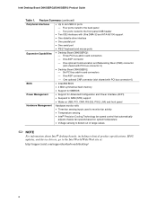
Four ports routed to the Intel World Wide Web site at: http://support.intel.com/support/motherboards/desktop/ 8 Three PCI bus add-in card connectors - One AGP ...Intel® desktop boards, including technical product specifications, BIOS updates, and device drivers, go to the back panel - Two ports routed to six USB 2.0 ports - Six PCI bus add-in card connectors - Feature Summary (continued) Peripheral Interfaces • Up to the front panel USB header • Two IDE interfaces with PCI bus connector 3) • Desktop Board D845GEBV2: - Intel Desktop Board D845GERG2...
Four ports routed to the Intel World Wide Web site at: http://support.intel.com/support/motherboards/desktop/ 8 Three PCI bus add-in card connectors - One AGP ...Intel® desktop boards, including technical product specifications, BIOS updates, and device drivers, go to the back panel - Two ports routed to six USB 2.0 ports - Six PCI bus add-in card connectors - Feature Summary (continued) Peripheral Interfaces • Up to the front panel USB header • Two IDE interfaces with PCI bus connector 3) • Desktop Board D845GEBV2: - Intel Desktop Board D845GERG2...
Product Guide
Page 9
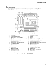
... fan connector (fan speed control) H Intel 82845GE (GMCH) W BIOS configuration jumper I Processor socket X Front panel header J Processor fan connector Y Intel 82801DB (ICH4) K DIMM sockets Z Front panel USB 2.0 header L Super I/O controller AA AGP connector M Main power connector BB PCI bus add-in card connectors N Diskette drive connector CC CNR (optional) O Secondary IDE connector Figure 1. Desktop Board D845GERG2 Components 9
... fan connector (fan speed control) H Intel 82845GE (GMCH) W BIOS configuration jumper I Processor socket X Front panel header J Processor fan connector Y Intel 82801DB (ICH4) K DIMM sockets Z Front panel USB 2.0 header L Super I/O controller AA AGP connector M Main power connector BB PCI bus add-in card connectors N Diskette drive connector CC CNR (optional) O Secondary IDE connector Figure 1. Desktop Board D845GERG2 Components 9
Product Guide
Page 10
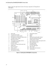
Intel Desktop Board D845GERG2/D845GEBV2 Product Guide Figure 2 shows the approximate location of the major components on Desktop Board D845GEBV2. Desktop Board D845GEBV2 Components 10 A B CD E F G CC H I BB AA Z J Y K L X WV UT S R Q PO NM OM13589 A Audio codec P Primary IDE connector B Front panel audio header Q Speaker C Auxiliary line-in connector (ATAPI) R Battery D Rear chassis fan connector (fan speed control) S SCSI hard drive...
Intel Desktop Board D845GERG2/D845GEBV2 Product Guide Figure 2 shows the approximate location of the major components on Desktop Board D845GEBV2. Desktop Board D845GEBV2 Components 10 A B CD E F G CC H I BB AA Z J Y K L X WV UT S R Q PO NM OM13589 A Audio codec P Primary IDE connector B Front panel audio header Q Speaker C Auxiliary line-in connector (ATAPI) R Battery D Rear chassis fan connector (fan speed control) S SCSI hard drive...
Product Guide
Page 14
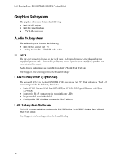
... Wide Web site: http://support.intel.com/support/motherboards/desktop/ LAN Subsystem (Optional) The optional LAN (with status indicator LEDs • Programmable transit threshold • Configurable EEPROM that contains the MAC address LAN Subsystem Software For LAN software and drivers, refer to the D845GERG2 or D845GEBV2 link on the back panel, is designed to this...
... Wide Web site: http://support.intel.com/support/motherboards/desktop/ LAN Subsystem (Optional) The optional LAN (with status indicator LEDs • Programmable transit threshold • Configurable EEPROM that contains the MAC address LAN Subsystem Software For LAN software and drivers, refer to the D845GERG2 or D845GEBV2 link on the back panel, is designed to this...
Product Guide
Page 15
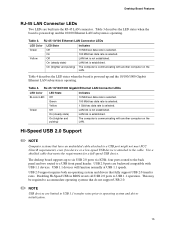
... device. LAN link is attached to operating system and driver initialization. 15 The desktop board supports up and the 10/100 Ethernet LAN subsystem is established. Table 3. LAN link is operating. Desktop Board Features RJ-45 LAN Connector LEDs Two LEDs are backward compatible with USB 1.1 devices... 1 Gbit/sec data rate is established. The computer is communicating with another computer on the LAN. four ports routed to the back panel and two routed to USB 1.1 operation. USB 1.1 devices will function normally at USB 1.1 speeds. Disabling Hi-Speed USB in BIOS ...
... device. LAN link is attached to operating system and driver initialization. 15 The desktop board supports up and the 10/100 Ethernet LAN subsystem is established. Table 3. LAN link is operating. Desktop Board Features RJ-45 LAN Connector LEDs Two LEDs are backward compatible with USB 1.1 devices... 1 Gbit/sec data rate is established. The computer is communicating with another computer on the LAN. four ports routed to the back panel and two routed to USB 1.1 operation. USB 1.1 devices will function normally at USB 1.1 speeds. Disabling Hi-Speed USB in BIOS ...

Product Guide
Page 18
...is lit when there is indicated by a wake-up device or event, the system quickly returns to its last known awake state. Intel Desktop Board D845GERG2/D845GEBV2 Product Guide ACPI ACPI gives the operating system direct control over the power management and Plug & Play functions of ACPI with the...the LED turning amber. If the system has a dual-colored power LED on the front panel, the sleep state is standby power to be off . Location of delivering adequate +5 V standby current. The desktop board's standby power indicator, shown in the S3 sleep state, the computer will appear to the...
...is lit when there is indicated by a wake-up device or event, the system quickly returns to its last known awake state. Intel Desktop Board D845GERG2/D845GEBV2 Product Guide ACPI ACPI gives the operating system direct control over the power management and Plug & Play functions of ACPI with the...the LED turning amber. If the system has a dual-colored power LED on the front panel, the sleep state is standby power to be off . Location of delivering adequate +5 V standby current. The desktop board's standby power indicator, shown in the S3 sleep state, the computer will appear to the...
Product Guide
Page 21
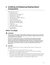
... at an ESD workstation using and modifying electronic equipment. 2 Installing and Replacing Desktop Board Components This chapter tells you how to: • Install the I/O shield • Install and remove the desktop board • Install and remove a processor • Install and remove memory &#...8226; Install and remove an AGP or ADD card • Connect the IDE cable • Connect the front panel header • Install the front panel audio solution • Install the front panel USB ...
... at an ESD workstation using and modifying electronic equipment. 2 Installing and Replacing Desktop Board Components This chapter tells you how to: • Install the I/O shield • Install and remove the desktop board • Install and remove a processor • Install and remove memory &#...8226; Install and remove an AGP or ADD card • Connect the IDE cable • Connect the front panel header • Install the front panel audio solution • Install the front panel USB ...

Product Guide
Page 28
... the screw (B) that secures the card's metal bracket (A) to the chassis back panel with a screw. B E A C D Figure 9. Press down on page 21. 2. Removing the AGP or ADD Card OM10595 28 Removing the AGP or ADD Card Follow these instructions ... the precautions in "Before You Begin" on the card until the retention pin (C) completely clears the notch in the card. 4. Push back on page 21. 2. Intel Desktop Board D845GERG2/D845GEBV2 Product Guide Installing an AGP or ADD Card Follow these instructions to remove the AGP or ADD card from the RM: 1. Pull the card...
... the screw (B) that secures the card's metal bracket (A) to the chassis back panel with a screw. B E A C D Figure 9. Press down on page 21. 2. Removing the AGP or ADD Card OM10595 28 Removing the AGP or ADD Card Follow these instructions ... the precautions in "Before You Begin" on the card until the retention pin (C) completely clears the notch in the card. 4. Push back on page 21. 2. Intel Desktop Board D845GERG2/D845GEBV2 Product Guide Installing an AGP or ADD Card Follow these instructions to remove the AGP or ADD card from the RM: 1. Pull the card...

Product Guide
Page 30
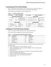
Intel Desktop Board D845GERG2/D845GEBV2 Product Guide Connecting Front Panel Headers Before connecting the front panel header, observe the precautions in "Before You Begin" on page 21. 1 2 3 4 A5 6 7 9 10 1 2 3 4 B5 6 7 8 10 1 2 3 4 C5 6 7 8 9 D Item A B C D Description Front panel audio Front panel USB Front panel Alternate power/sleep LED Figure 11. Front Panel Headers OM13616 30
Intel Desktop Board D845GERG2/D845GEBV2 Product Guide Connecting Front Panel Headers Before connecting the front panel header, observe the precautions in "Before You Begin" on page 21. 1 2 3 4 A5 6 7 9 10 1 2 3 4 B5 6 7 8 10 1 2 3 4 C5 6 7 8 9 D Item A B C D Description Front panel audio Front panel USB Front panel Alternate power/sleep LED Figure 11. Front Panel Headers OM13616 30
Product Guide
Page 31
Table 6 shows the pin assignments for the front panel header. Remove the cover. 4. Connect the audio cable to the front panel audio header, follow these steps: 1. Installing and Replacing Desktop Board Components Connecting the Front Panel Header Before connecting the front panel header, observe the precautions in "Before You Begin" on page 21. Table 5 shows the pin...
Table 6 shows the pin assignments for the front panel header. Remove the cover. 4. Connect the audio cable to the front panel audio header, follow these steps: 1. Installing and Replacing Desktop Board Components Connecting the Front Panel Header Before connecting the front panel header, observe the precautions in "Before You Begin" on page 21. Table 5 shows the pin...

Product Guide
Page 32
... (rear R channel). 6. Signal name VREG_FP_USBPWR0 USB_FPP1USB_FPP1+ Ground USB_FP_OC0 32 Intel Desktop Board D845GERG2/D845GEBV2 Product Guide To restore back panel operations, follow these steps: 1. Remove the front panel audio cable. 5. Table 7. Remove the cover. 4. Front Panel USB 2.0 Header (J9F1) Pin Signal name Pin 1 VREG_FP_WSBPWR0 2 3...6 7 Ground 8 9 Key 10 Note: USB ports may be assigned as needed. Installing a Front Panel USB Solution Before installing a front panel USB 2.0 solution, observe the precautions in "Before You Begin" on page 21. 2. Turn off all ...
... (rear R channel). 6. Signal name VREG_FP_USBPWR0 USB_FPP1USB_FPP1+ Ground USB_FP_OC0 32 Intel Desktop Board D845GERG2/D845GEBV2 Product Guide To restore back panel operations, follow these steps: 1. Remove the front panel audio cable. 5. Table 7. Remove the cover. 4. Front Panel USB 2.0 Header (J9F1) Pin Signal name Pin 1 VREG_FP_WSBPWR0 2 3...6 7 Ground 8 9 Key 10 Note: USB ports may be assigned as needed. Installing a Front Panel USB Solution Before installing a front panel USB 2.0 solution, observe the precautions in "Before You Begin" on page 21. 2. Turn off all ...

Product Guide
Page 63
... provide operating voltage (+5 V dc and +12 V dc, for powering devices external to the computer chassis. A fault in board and peripheral interface connectors CAUTION Many of the: • Back panel connectors • Audio connectors • Add-in the load presented by the external devices could cause damage to devices inside the computer chassis...
... provide operating voltage (+5 V dc and +12 V dc, for powering devices external to the computer chassis. A fault in board and peripheral interface connectors CAUTION Many of the: • Back panel connectors • Audio connectors • Add-in the load presented by the external devices could cause damage to devices inside the computer chassis...
Product Guide
Page 64
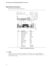
Intel Desktop Board D845GERG2/D845GEBV2 Product Guide Back Panel Connectors Figure 15 shows the back panel connectors. Back Panel Connectors ✏ NOTE The line out connector, located on the back panel, is designed to this output. 64 Poor audio quality may occur if passive (non-amplified) speakers are connected to power either headphones or amplified speakers ...
Intel Desktop Board D845GERG2/D845GEBV2 Product Guide Back Panel Connectors Figure 15 shows the back panel connectors. Back Panel Connectors ✏ NOTE The line out connector, located on the back panel, is designed to this output. 64 Poor audio quality may occur if passive (non-amplified) speakers are connected to power either headphones or amplified speakers ...

Product Guide
Page 65
BC 1 2 3 4 A5 6 7 9 10 4 1 4 1 Technical Reference Item A B C Description Color Front panel audio Auxiliary line in (ATAPI) CD-ROM (ATAPI) Black Grey Black Figure 16. Audio Connectors OM13612 65 Audio Connectors Figure 11 shows the approximate location of the audio connectors.
BC 1 2 3 4 A5 6 7 9 10 4 1 4 1 Technical Reference Item A B C Description Color Front panel audio Auxiliary line in (ATAPI) CD-ROM (ATAPI) Black Grey Black Figure 16. Audio Connectors OM13612 65 Audio Connectors Figure 11 shows the approximate location of the audio connectors.


