Product Guide
Page 5
... Devices Submenu...76 ATAPI CDROM Drives...77 Exit Menu ...77 5 Technical Reference Desktop Board Connectors ...79 Back Panel Connectors ...80 Midboard Connectors ...81 Front Panel Connectors...85 Desktop Board Resources...86 Interrupts ...86 A Error Messages and Indicators BIOS Beep Codes ...87...Clips to the Processor Socket ...37 v D815EEA2 and D815EPEA2 Desktop Board Components...12 D815EFV and D815EPFV Desktop Board Components ...13 Location of Standby Power Indicator (the D815EEA2 Board Is Shown)...24 DIMM Socket Locations (the D815EEA2 Board Is Shown) ...27 Retention Notch Shown ...
... Devices Submenu...76 ATAPI CDROM Drives...77 Exit Menu ...77 5 Technical Reference Desktop Board Connectors ...79 Back Panel Connectors ...80 Midboard Connectors ...81 Front Panel Connectors...85 Desktop Board Resources...86 Interrupts ...86 A Error Messages and Indicators BIOS Beep Codes ...87...Clips to the Processor Socket ...37 v D815EEA2 and D815EPEA2 Desktop Board Components...12 D815EFV and D815EPFV Desktop Board Components ...13 Location of Standby Power Indicator (the D815EEA2 Board Is Shown)...24 DIMM Socket Locations (the D815EEA2 Board Is Shown) ...27 Retention Notch Shown ...
Product Guide
Page 6
... Settings for the D815EFV and D815EPFV Boards...84 33. Add-in Board and Peripheral Interface Connectors for the D815EEA2 and D815EPEA2 Boards ...83 32. Intel Desktop Boards D815EEA2, D815EPEA2, D815EFV, and D815EPFV Product Guide 16. 17. 18. 19. 20. 21. 22. 23. 24. 25. 26. 27. 28. 29. 30. 31. Front Panel Connectors (the D815EEA2 Board Is Shown) ...85 Tables 1. 2. 3. 4. 5. 6. 7. 8. 9. 10...
... Settings for the D815EFV and D815EPFV Boards...84 33. Add-in Board and Peripheral Interface Connectors for the D815EEA2 and D815EPEA2 Boards ...83 32. Intel Desktop Boards D815EEA2, D815EPEA2, D815EFV, and D815EPFV Product Guide 16. 17. 18. 19. 20. 21. 22. 23. 24. 25. 26. 27. 28. 29. 30. 31. Front Panel Connectors (the D815EEA2 Board Is Shown) ...85 Tables 1. 2. 3. 4. 5. 6. 7. 8. 9. 10...

Product Guide
Page 10
...; Two serial ports: one back panel and one internal connector • Four USB ports: four back panel and two optional front panel • One parallel port • Two IDE interfaces with Ultra DMA (33 MB/sec) and ATA-66/100 support • One diskette drive interface • PS/2 Intel Desktop Boards D815EEA2, D815EPEA2, D815EFV, and D815EPFV Product...
...; Two serial ports: one back panel and one internal connector • Four USB ports: four back panel and two optional front panel • One parallel port • Two IDE interfaces with Ultra DMA (33 MB/sec) and ATA-66/100 support • One diskette drive interface • PS/2 Intel Desktop Boards D815EEA2, D815EPEA2, D815EFV, and D815EPFV Product...

Product Guide
Page 11
... connector: • Slot shared with PCI bus connector 5 on D815EEA2 and D815EPEA2 boards. • Slot shared with integrated LED's located on D815EFV and D815EPFV boards. Desktop Board Features Manufacturing Options Table 3 describes the manufacturing options of the boards. Intel® 82562ET that provides a basic interface to the front panel. Routes mic in network interface card with remote wake...
... connector: • Slot shared with PCI bus connector 5 on D815EEA2 and D815EPEA2 boards. • Slot shared with integrated LED's located on D815EFV and D815EPFV boards. Desktop Board Features Manufacturing Options Table 3 describes the manufacturing options of the boards. Intel® 82562ET that provides a basic interface to the front panel. Routes mic in network interface card with remote wake...

Product Guide
Page 12
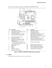
Intel Desktop Boards D815EEA2, D815EPEA2, D815EFV, and D815EPFV Product Guide Components Figure 1 shows the major components on all the boards. 12 AD1885 audio codec AGP universal connector ATAPI-style auxiliary line in connector Front panel audio connector (optional) ATAPI-style CD-ROM connector Back panel connectors Processor fan connector (fan 1, tach) Digital Video Output (DVO) connector (D815EEA2 only) •...
Intel Desktop Boards D815EEA2, D815EPEA2, D815EFV, and D815EPFV Product Guide Components Figure 1 shows the major components on all the boards. 12 AD1885 audio codec AGP universal connector ATAPI-style auxiliary line in connector Front panel audio connector (optional) ATAPI-style CD-ROM connector Back panel connectors Processor fan connector (fan 1, tach) Digital Video Output (DVO) connector (D815EEA2 only) •...
Product Guide
Page 13
... Desktop Board Components ✏ NOTE Components labeled optional do not come on the D815EFV and D815EPFV boards. AD1885 audio codec AGP universal connector ATAPI-style auxiliary line in connector Front panel audio connector (optional) ATAPI-style CD-ROM connector Back panel connectors Processor fan connector (fan 1, tach) Digital Video Output (DVO) connector (D815EFV only) • Intel...
... Desktop Board Components ✏ NOTE Components labeled optional do not come on the D815EFV and D815EPFV boards. AD1885 audio codec AGP universal connector ATAPI-style auxiliary line in connector Front panel audio connector (optional) ATAPI-style CD-ROM connector Back panel connectors Processor fan connector (fan 1, tach) Digital Video Output (DVO) connector (D815EFV only) • Intel...

Product Guide
Page 17
Desktop Board Features Intel® 82815E Graphics Memory Controller Hub (GMCH) The GMCH provides the following An integrated Synchronous DRAM memory controller with autodetection of SDRAM An interface for a single AGP device or a Graphics Performance Accelerator (GPA) card An interface for a digital video output (DVO) connector for a flat panel... Hub (ICH2) The Intel 82801BA ICH2 has these features: • 33 MHz Peripheral Component Interface (PCI) Local Bus slots supporting PCI specification, rev 2.2: Four PCI plus one PCI/CNR shared connector (D815EEA2 Two PCI plus one PCI...
Desktop Board Features Intel® 82815E Graphics Memory Controller Hub (GMCH) The GMCH provides the following An integrated Synchronous DRAM memory controller with autodetection of SDRAM An interface for a single AGP device or a Graphics Performance Accelerator (GPA) card An interface for a digital video output (DVO) connector for a flat panel... Hub (ICH2) The Intel 82801BA ICH2 has these features: • 33 MHz Peripheral Component Interface (PCI) Local Bus slots supporting PCI specification, rev 2.2: Four PCI plus one PCI/CNR shared connector (D815EEA2 Two PCI plus one PCI...
Product Guide
Page 18
... stacked back panel connectors and the other port is accessible through a CNR add-in ports. USB Support The desktop boards have a time-of-day clock and 100-year calendar. The desktop board supports the Universal Host Controller Interface (UHCI) and takes advantage of standard software drivers written to the computer without an external hub. Intel Desktop Boards D815EEA2, D815EPEA2...
... stacked back panel connectors and the other port is accessible through a CNR add-in ports. USB Support The desktop boards have a time-of-day clock and 100-year calendar. The desktop board supports the Universal Host Controller Interface (UHCI) and takes advantage of standard software drivers written to the computer without an external hub. Intel Desktop Boards D815EEA2, D815EPEA2...
Product Guide
Page 21
... the password prompt of Setup gives the user restricted access to access Setup. the LAN subsystem is mounted on the desktop boards. Desktop Board Features Security Passwords The BIOS includes security features that restrict whether the BIOS Setup program can be set for the Setup.... • Speaker A 47 Ω inductive speaker is completely software configurable Intel® 82562ET Platform LAN Connect Device The Intel 82562ET LAN component provides an interface to the back panel RJ-45 connector with status indicator LEDs Full driver compatibility Advanced Power Management (APM...
... the password prompt of Setup gives the user restricted access to access Setup. the LAN subsystem is mounted on the desktop boards. Desktop Board Features Security Passwords The BIOS includes security features that restrict whether the BIOS Setup program can be set for the Setup.... • Speaker A 47 Ω inductive speaker is completely software configurable Intel® 82562ET Platform LAN Connect Device The Intel 82562ET LAN component provides an interface to the back panel RJ-45 connector with status indicator LEDs Full driver compatibility Advanced Power Management (APM...

Product Guide
Page 23
... current when implementing Wake on LAN technology can damage the power supply. For more information about front panel LED states, see the Intel ® Desktop Board D815EEA2/D815EPEA2 Technical Product Specification or Intel ® Desktop Board D815EFV/D815EPFV Technical Product Specification. 23 Desktop Board Features Wake on LAN Technology (Optional) CAUTION For Wake on LAN technology, the 5-V standby line for...
... current when implementing Wake on LAN technology can damage the power supply. For more information about front panel LED states, see the Intel ® Desktop Board D815EEA2/D815EPEA2 Technical Product Specification or Intel ® Desktop Board D815EFV/D815EPFV Technical Product Specification. 23 Desktop Board Features Wake on LAN Technology (Optional) CAUTION For Wake on LAN technology, the 5-V standby line for...
Product Guide
Page 25
...part of the procedures described in this chapter. CAUTION The procedures in the correct order. Some circuitry on the desktop board can damage components. 2 Installing and Replacing Desktop Board Components This chapter tells you how to Install and remove memory Install and remove the AGP card retention mechanism (...an anti-static wrist strap and a conductive foam pad. Electrostatic discharge (ESD) can continue to operate even though the front panel power button is not available, you open the computer or perform any of the computer chassis. Perform the procedures described in ...
...part of the procedures described in this chapter. CAUTION The procedures in the correct order. Some circuitry on the desktop board can damage components. 2 Installing and Replacing Desktop Board Components This chapter tells you how to Install and remove memory Install and remove the AGP card retention mechanism (...an anti-static wrist strap and a conductive foam pad. Electrostatic discharge (ESD) can continue to operate even though the front panel power button is not available, you open the computer or perform any of the computer chassis. Perform the procedures described in ...

Product Guide
Page 31
...and Removing the AGP Card 31 Installing and Replacing Desktop Board Components Installing and Removing AGP and GPA Cards Installing ...even a little during installation can damage the pins of the AGP socket. Allowing the card to the chassis back panel. 2. If the card has a metal bracket (B), secure the card's metal bracket to install an AGP card...completely seated in the card. 3. Removing the AGP Card from the Retention Mechanism Follow these instructions to the chassis back panel with the memory retention mechanism. A B E D C OM10219 Figure 8. CAUTION When installing an AGP card, press...
...and Removing the AGP Card 31 Installing and Replacing Desktop Board Components Installing and Removing AGP and GPA Cards Installing ...even a little during installation can damage the pins of the AGP socket. Allowing the card to the chassis back panel. 2. If the card has a metal bracket (B), secure the card's metal bracket to install an AGP card...completely seated in the card. 3. Removing the AGP Card from the Retention Mechanism Follow these instructions to the chassis back panel with the memory retention mechanism. A B E D C OM10219 Figure 8. CAUTION When installing an AGP card, press...

Product Guide
Page 32
... connector's retention mechanism (RM). 2. A C B D F E F G OM10410 Figure 9. Press down on the GPA card points toward the back panel I/O of the RM (B). Before inserting the GPA card, verify that the arrow (A) on both ends of the card's edge plug align squarely over the... mechanism. Push the card in direction (C) while lowering (but not inserting) the card in direction (D). Intel Desktop Boards D815EEA2, D815EPEA2, D815EFV, and D815EPFV Product Guide Installing and Removing a GPA Card (D815EEA2 and D815EFV only) CAUTION Remove the GPA video card before inserting.
... connector's retention mechanism (RM). 2. A C B D F E F G OM10410 Figure 9. Press down on the GPA card points toward the back panel I/O of the RM (B). Before inserting the GPA card, verify that the arrow (A) on both ends of the card's edge plug align squarely over the... mechanism. Push the card in direction (C) while lowering (but not inserting) the card in direction (D). Intel Desktop Boards D815EEA2, D815EPEA2, D815EFV, and D815EPFV Product Guide Installing and Removing a GPA Card (D815EEA2 and D815EFV only) CAUTION Remove the GPA video card before inserting.

Product Guide
Page 79
... use these connectors for example) to the computer chassis. The desktop board connectors can be divided into three groups, as fans and internal peripherals. Connector Groups (the D815EEA2 Board Is Shown) 79 Back panel connectors (see page 80) A A B B Midboard connectors (see page 81) C C OM11637 Front panel connectors (see page 85) Figure 27. A fault in Figure 27...
... use these connectors for example) to the computer chassis. The desktop board connectors can be divided into three groups, as fans and internal peripherals. Connector Groups (the D815EEA2 Board Is Shown) 79 Back panel connectors (see page 80) A A B B Midboard connectors (see page 81) C C OM11637 Front panel connectors (see page 85) Figure 27. A fault in Figure 27...
Product Guide
Page 80
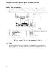
... connector with PC 99 recommendations. The figure legend below lists the colors used. Back Panel Connectors (the D815EEA2 Board Is Shown) ✏ NOTE The line out connector, located on the desktop board. Intel Desktop Boards D815EEA2, D815EPEA2, D815EFV, and D815EPFV Product Guide Back Panel Connectors Figure 28 shows the back panel connectors on the back panel, is designed to this output. 80
... connector with PC 99 recommendations. The figure legend below lists the colors used. Back Panel Connectors (the D815EEA2 Board Is Shown) ✏ NOTE The line out connector, located on the desktop board. Intel Desktop Boards D815EEA2, D815EPEA2, D815EFV, and D815EPFV Product Guide Back Panel Connectors Figure 28 shows the back panel connectors on the back panel, is designed to this output. 80

Product Guide
Page 81
A B C 9 10 4 1 1 2 4 1 OM11638 Item A B C Description ATAPI-style auxiliary line in Front panel audio (optional) ATAPI-style CD-ROM Figure 29. Audio Connectors (the D815EEA2 Board Is Shown) 81 Technical Reference Midboard Connectors Audio Connectors Figure 29 shows the location of the audio connectors.
A B C 9 10 4 1 1 2 4 1 OM11638 Item A B C Description ATAPI-style auxiliary line in Front panel audio (optional) ATAPI-style CD-ROM Figure 29. Audio Connectors (the D815EEA2 Board Is Shown) 81 Technical Reference Midboard Connectors Audio Connectors Figure 29 shows the location of the audio connectors.

Product Guide
Page 82
Intel Desktop Boards D815EEA2, D815EPEA2, D815EFV, and D815EPFV Product Guide Power and Hardware Control Connectors Figure 30 shows the power and hardware connectors. Power and Hardware Control Connectors (the D815EEA2 Board Is Shown) 82 A 1 2 1 1 7 10 1 1 11 10 20 H GF E Item A B C D E F G H D Description Processor fan (fan 1) Power Chassis fan (fan 3) Front panel USB (optional) SCSI LED Chassis fan (fan 2) Chassis intrusion C B OM11631 Wake on LAN technology (optional) Figure 30.
Intel Desktop Boards D815EEA2, D815EPEA2, D815EFV, and D815EPFV Product Guide Power and Hardware Control Connectors Figure 30 shows the power and hardware connectors. Power and Hardware Control Connectors (the D815EEA2 Board Is Shown) 82 A 1 2 1 1 7 10 1 1 11 10 20 H GF E Item A B C D E F G H D Description Processor fan (fan 1) Power Chassis fan (fan 3) Front panel USB (optional) SCSI LED Chassis fan (fan 2) Chassis intrusion C B OM11631 Wake on LAN technology (optional) Figure 30.

Product Guide
Page 85
Technical Reference Front Panel Connectors Figure 33 shows the location of the front panel connectors. 3 1 B 15 16 C D 1 2 15 1 A J9H2 I HG F E 16 J9H3 2 OM11618 Item A B C D E Description Alternate front panel power LED connector Reserved Reset switch Hard drive activity LED Power LED Item F G H I Description On/Off switch No connect Ground +5 V Figure 33. Front Panel Connectors (the D815EEA2 Board Is Shown) 85
Technical Reference Front Panel Connectors Figure 33 shows the location of the front panel connectors. 3 1 B 15 16 C D 1 2 15 1 A J9H2 I HG F E 16 J9H3 2 OM11618 Item A B C D E Description Alternate front panel power LED connector Reserved Reset switch Hard drive activity LED Power LED Item F G H I Description On/Off switch No connect Ground +5 V Figure 33. Front Panel Connectors (the D815EEA2 Board Is Shown) 85


