

Technical product specification
Page 5
... of the board The features supported by the BIOS Setup program A description of the BIOS error messages, beep codes, and POST codes Regulatory compliance and battery disposal information Typographical Conventions This section contains information about the Intel Desktop Board D2550MUD2 and its components to provide detailed, technical information about the conventions used in all specifications of information. v It describes the standard product and available manufacturing options. Notes, Cautions...
... of the board The features supported by the BIOS Setup program A description of the BIOS error messages, beep codes, and POST codes Regulatory compliance and battery disposal information Typographical Conventions This section contains information about the Intel Desktop Board D2550MUD2 and its components to provide detailed, technical information about the conventions used in all specifications of information. v It describes the standard product and available manufacturing options. Notes, Cautions...

Technical product specification
Page 8
... PCI* Autoconfiguration 66 3.4 System Management BIOS (SMBIOS 67 3.5 Legacy USB Support 68 3.6 BIOS Updates 69 3.6.1 BIOS Recovery 69 3.6.2 Custom Splash Screen 70 3.7 Boot Options 70 3.7.1 Optical Drive Boot 70 3.7.2 Network Boot 70 3.7.3 Booting Without Attached Devices 71 3.7.4 Changing the Default Boot Device During POST 71 3.8 Adjusting Boot Speed 71 3.8.1 Peripheral Selection and Configuration 71 3.8.2 BIOS Boot Optimizations 72 3.9 BIOS Security Features 73 4 Board Status and Error Messages 4.1 BIOS Beep Codes 75 4.2 Front-panel Power LED Blink Codes 76 4.3 BIOS Error...
... PCI* Autoconfiguration 66 3.4 System Management BIOS (SMBIOS 67 3.5 Legacy USB Support 68 3.6 BIOS Updates 69 3.6.1 BIOS Recovery 69 3.6.2 Custom Splash Screen 70 3.7 Boot Options 70 3.7.1 Optical Drive Boot 70 3.7.2 Network Boot 70 3.7.3 Booting Without Attached Devices 71 3.7.4 Changing the Default Boot Device During POST 71 3.8 Adjusting Boot Speed 71 3.8.1 Peripheral Selection and Configuration 71 3.8.2 BIOS Boot Optimizations 72 3.9 BIOS Security Features 73 4 Board Status and Error Messages 4.1 BIOS Beep Codes 75 4.2 Front-panel Power LED Blink Codes 76 4.3 BIOS Error...
Technical product specification
Page 9
... 8. Front Panel Audio Header for Front Panel USB Header with Intel Z-USB Solid-State Drive or Compatible Device Support 54 15. Memory Channel and SO-DIMM Configuration 19 4. Location of Pressing the Power Switch 30 7. Location of the BIOS Configuration Jumper Block 55 16. Component-side Connectors and Headers Shown in Figure 1 14 3. Serial Port Headers 45 13. FPD Brightness Connector 47 16. LVDS Inverter Power Voltage Selection Jumper 47 17. SATA Connectors 48 19. Block Diagram 15 3. LAN Connector LED Locations 25 5. Connection Diagram for Intel HD Audio 48...
... 8. Front Panel Audio Header for Front Panel USB Header with Intel Z-USB Solid-State Drive or Compatible Device Support 54 15. Memory Channel and SO-DIMM Configuration 19 4. Location of Pressing the Power Switch 30 7. Location of the BIOS Configuration Jumper Block 55 16. Component-side Connectors and Headers Shown in Figure 1 14 3. Serial Port Headers 45 13. FPD Brightness Connector 47 16. LVDS Inverter Power Voltage Selection Jumper 47 17. SATA Connectors 48 19. Block Diagram 15 3. LAN Connector LED Locations 25 5. Connection Diagram for Intel HD Audio 48...

Technical product specification
Page 10
.... Fan Header Current Capability 58 29. Port 80h POST Code Ranges 77 42. EMC Regulations 87 46. Boot Device Menu Options 71 37. Supervisor and User Password Functions 73 38. Port 80h POST Codes 78 43. Front Panel USB Header 49 23. States for a One-Color Power LED 53 27. BIOS Setup Program Function Keys 66 35. BIOS Error Messages 76 41. Safety Standards 83 45. Intel Desktop Board D2550MUD2 Environmental Specifications 64 33. Regulatory Compliance Marks 91 x BIOS Configuration Jumper Settings 56...
.... Fan Header Current Capability 58 29. Port 80h POST Code Ranges 77 42. EMC Regulations 87 46. Boot Device Menu Options 71 37. Supervisor and User Password Functions 73 38. Port 80h POST Codes 78 43. Front Panel USB Header 49 23. States for a One-Color Power LED 53 27. BIOS Setup Program Function Keys 66 35. BIOS Error Messages 76 41. Safety Standards 83 45. Intel Desktop Board D2550MUD2 Environmental Specifications 64 33. Regulatory Compliance Marks 91 x BIOS Configuration Jumper Settings 56...

Technical product specification
Page 11
... microATX Passively-cooled, soldered-down Dual-Core Intel® Atom™ processor with an internal header (brown-colored) that supports an Intel® Z-U130 USB Solid-State Drive or compatible device • Two Serial ATA (SATA) 3.0 Gb/s connectors (supporting IDE and AHCI mode) • One parallel port connector on the back panel • Two serial port headers • PS/2-style keyboard/ mouse ports 10/100/1000 Mb/s Ethernet LAN subsystem using an Intel® 82574L Gigabit Ethernet Controller continued 11 Table 1.
... microATX Passively-cooled, soldered-down Dual-Core Intel® Atom™ processor with an internal header (brown-colored) that supports an Intel® Z-U130 USB Solid-State Drive or compatible device • Two Serial ATA (SATA) 3.0 Gb/s connectors (supporting IDE and AHCI mode) • One parallel port connector on the back panel • Two serial port headers • PS/2-style keyboard/ mouse ports 10/100/1000 Mb/s Ethernet LAN subsystem using an Intel® 82574L Gigabit Ethernet Controller continued 11 Table 1.

Technical product specification
Page 12
Intel Desktop Board D2550MUD2 Technical Product Specification Table 1. Feature Summary (continued) BIOS • Intel® BIOS (resident in the SPI Flash device) • Support for Advanced Configuration and Power Interface (ACPI), Plug and Play, and SMBIOS Instantly Available • Suspend to RAM support PC Technology • Wake on PCI, PCI Express*, PS/2, serial, front panel, USB ports, and LAN Expansion Capabilities • One Conventional PCI bus connector (with riser card support for up to two PCI cards) • One PCI Express Full-/Half-Mini Card slot Hardware Monitor...
Intel Desktop Board D2550MUD2 Technical Product Specification Table 1. Feature Summary (continued) BIOS • Intel® BIOS (resident in the SPI Flash device) • Support for Advanced Configuration and Power Interface (ACPI), Plug and Play, and SMBIOS Instantly Available • Suspend to RAM support PC Technology • Wake on PCI, PCI Express*, PS/2, serial, front panel, USB ports, and LAN Expansion Capabilities • One Conventional PCI bus connector (with riser card support for up to two PCI cards) • One PCI Express Full-/Half-Mini Card slot Hardware Monitor...

Technical product specification
Page 14
... Chipset L SATA connectors M System fan header N Front panel header O BIOS setup configuration jumper block P Battery Q Front panel USB 2.0 header R Front Panel Wireless Activity LED header S Piezo/monotonic speaker header T Conventional PCI bus add-in card connector U PCI Express Full-/Half-Mini Card slot V Serial port header, COMM 2 W FPD brightness connector X LVDS inverter power voltage selection jumper Y Front panel audio header Z Front panel USB header that supports an Intel Z-U130 USB Solid-State Drive or compatible device (brown-colored)) AA Serial port...
... Chipset L SATA connectors M System fan header N Front panel header O BIOS setup configuration jumper block P Battery Q Front panel USB 2.0 header R Front Panel Wireless Activity LED header S Piezo/monotonic speaker header T Conventional PCI bus add-in card connector U PCI Express Full-/Half-Mini Card slot V Serial port header, COMM 2 W FPD brightness connector X LVDS inverter power voltage selection jumper Y Front panel audio header Z Front panel USB header that supports an Intel Z-U130 USB Solid-State Drive or compatible device (brown-colored)) AA Serial port...

Technical product specification
Page 16
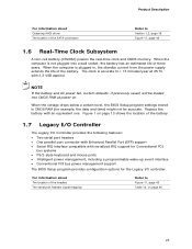
... are recommended above the processor heatsink area for the Intel http://ark.intel.com Desktop Board D2550MUD2 Supported processors Chipset information BIOS and driver updates Tested memory Integration information http://processormatch.intel.com http://www.intel.com/products/desktop/chipsets/index.htm http://downloadcenter.intel.com http://www.intel.com/support/motherboards/desktop/sb/CS025414.htm http://www.intel.com/support/go/buildit 1.3 Processor The board has a passively-cooled, soldered-down Dual-Core Intel Atom processor with integrated graphics and integrated memory controller.
... are recommended above the processor heatsink area for the Intel http://ark.intel.com Desktop Board D2550MUD2 Supported processors Chipset information BIOS and driver updates Tested memory Integration information http://processormatch.intel.com http://www.intel.com/products/desktop/chipsets/index.htm http://downloadcenter.intel.com http://www.intel.com/support/motherboards/desktop/sb/CS025414.htm http://www.intel.com/support/go/buildit 1.3 Processor The board has a passively-cooled, soldered-down Dual-Core Intel Atom processor with integrated graphics and integrated memory controller.
Technical product specification
Page 18
... effectiveness. • If you are subject to change. 2. This allows the BIOS to read the SPD data and program the chipset to accurately configure memory settings for one SO-DIMM, it must be installed in a properly ventilated chassis. Intel Desktop Board D2550MUD2 Technical Product Specification 1.4 System Memory The board has two 204-pin DDR3 SO-DIMM sockets and supports the following memory features: • DDR3 SDRAM SO-DIMMs with...
... effectiveness. • If you are subject to change. 2. This allows the BIOS to read the SPD data and program the chipset to accurately configure memory settings for one SO-DIMM, it must be installed in a properly ventilated chassis. Intel Desktop Board D2550MUD2 Technical Product Specification 1.4 System Memory The board has two 204-pin DDR3 SO-DIMM sockets and supports the following memory features: • DDR3 SDRAM SO-DIMMs with...

Technical product specification
Page 22
...full-speed devices. Internal flat panel display connectivity is used for configurations using the Windows Vista* operating system. 22 The board's SATA controller offers independent SATA ports with the following: 1. The SATA controller supports IDE and AHCI configuration and can be installed on each port for a maximum of 3.0 Gb/s on each channel. In native mode, standard Conventional PCI bus resource steering is disabled (and all parameters hidden) by loading BIOS setup defaults. 4. Internal flat panel display settings will not be preserved across BIOS updates. 1.5.2 USB The...
...full-speed devices. Internal flat panel display connectivity is used for configurations using the Windows Vista* operating system. 22 The board's SATA controller offers independent SATA ports with the following: 1. The SATA controller supports IDE and AHCI configuration and can be installed on each port for a maximum of 3.0 Gb/s on each channel. In native mode, standard Conventional PCI bus resource steering is disabled (and all parameters hidden) by loading BIOS setup defaults. 4. Internal flat panel display settings will not be preserved across BIOS updates. 1.5.2 USB The...
Technical product specification
Page 23
... defaults, if previously saved, will be accurate. Replace the battery with serialized IRQ support for Conventional PCI bus systems • PS/2-style keyboard and mouse ports • Intelligent power management, including a programmable wake-up event interface • Conventional PCI bus power management support The BIOS Setup program provides configuration options for example, the date and time) might not be loaded into a wall socket, the battery has an estimated life of the SATA connectors Refer...
... defaults, if previously saved, will be accurate. Replace the battery with serialized IRQ support for Conventional PCI bus systems • PS/2-style keyboard and mouse ports • Intelligent power management, including a programmable wake-up event interface • Conventional PCI bus power management support The BIOS Setup program provides configuration options for example, the date and time) might not be loaded into a wall socket, the battery has an estimated life of the SATA connectors Refer...

Technical product specification
Page 26
... to the user's definition, or can be automatically switched depending on the recognized device type. • Front panel Intel HD Audio and AC '97 audio support. • 3-port analog audio out stack. • Windows Vista Basic certification. • A signal-to an audio port. Audio Jack Support Audio Jack Front panel - Green Back panel - Intel Desktop Board D2550MUD2 Technical Product Specification 1.9 Audio Subsystem The board supports the Intel® High Definition Audio (Intel® HD Audio) subsystem. Table 5. Pink Microphone Default Headphones Default (ctrl panel) Line...
... to the user's definition, or can be automatically switched depending on the recognized device type. • Front panel Intel HD Audio and AC '97 audio support. • 3-port analog audio out stack. • Windows Vista Basic certification. • A signal-to an audio port. Audio Jack Support Audio Jack Front panel - Green Back panel - Intel Desktop Board D2550MUD2 Technical Product Specification 1.9 Audio Subsystem The board supports the Intel® High Definition Audio (Intel® HD Audio) subsystem. Table 5. Pink Microphone Default Headphones Default (ctrl panel) Line...

Technical product specification
Page 30
... ACPI support. working state) Less than four seconds Sleep (ACPI G1 - Soft off (ACPI G2/G5 - Intel Desktop Board D2550MUD2 Technical Product Specification 1.11 Power Management Power management is implemented at several levels, including: • Software support through Advanced Configuration and Power Interface (ACPI) • Hardware support: Power connector Fan header LAN wake capabilities Instantly Available PC technology Wake from USB Wake from PS/2 devices Power Management Event signal (PME#) wake-up support...
... ACPI support. working state) Less than four seconds Sleep (ACPI G1 - Soft off (ACPI G2/G5 - Intel Desktop Board D2550MUD2 Technical Product Specification 1.11 Power Management Power management is implemented at several levels, including: • Software support through Advanced Configuration and Power Interface (ACPI) • Hardware support: Power connector Fan header LAN wake capabilities Instantly Available PC technology Wake from USB Wake from PS/2 devices Power Management Event signal (PME#) wake-up support...

Technical product specification
Page 38
Intel Desktop Board D2550MUD2 Technical Product Specification The amount of system addresses. All installed system memory can be used when there is no overlap of installed memory that can be used will vary based on add-in cards and BIOS settings. Detailed System Memory Address Map 38 Figure 8 shows a schematic of the system memory map. Figure 8.
Intel Desktop Board D2550MUD2 Technical Product Specification The amount of system addresses. All installed system memory can be used when there is no overlap of installed memory that can be used will vary based on add-in cards and BIOS settings. Detailed System Memory Address Map 38 Figure 8 shows a schematic of the system memory map. Figure 8.
Technical product specification
Page 54
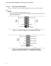
Connection Diagram for Front Panel USB Header with Intel Z-USB Solid-State Drive or Compatible Device Support 54 Connection Diagram for Front Panel USB Header Figure 14. Intel Desktop Board D2550MUD2 Technical Product Specification 2.2.2.5 Front Panel USB Headers Figure 13 and Figure 14 are connection diagrams for high-speed USB devices. Figure 13. NOTE • The +5 VDC power on the USB headers is fused. • Use only a front panel USB connector that conforms to the USB 2.0 specification for the front panel USB headers.
Connection Diagram for Front Panel USB Header with Intel Z-USB Solid-State Drive or Compatible Device Support 54 Connection Diagram for Front Panel USB Header Figure 14. Intel Desktop Board D2550MUD2 Technical Product Specification 2.2.2.5 Front Panel USB Headers Figure 13 and Figure 14 are connection diagrams for high-speed USB devices. Figure 13. NOTE • The +5 VDC power on the USB headers is fused. • Use only a front panel USB connector that conforms to the USB 2.0 specification for the front panel USB headers.

Technical product specification
Page 65
... put the board in configure mode. Maintenance Main Advanced Security Power Boot Exit NOTE The maintenance menu is displayed only when the board is stored in the Serial Peripheral Interface Flash Memory (SPI Flash) and can be updated using a disk-based program. Section 2.3 on page 55 shows how to view and change the BIOS settings for the computer. The SPI Flash contains the BIOS Setup program, POST, the PCI auto-configuration utility, LAN EEPROM information, and Plug and Play support.
... put the board in configure mode. Maintenance Main Advanced Security Power Boot Exit NOTE The maintenance menu is displayed only when the board is stored in the Serial Peripheral Interface Flash Memory (SPI Flash) and can be updated using a disk-based program. Section 2.3 on page 55 shows how to view and change the BIOS settings for the computer. The SPI Flash contains the BIOS Setup program, POST, the PCI auto-configuration utility, LAN EEPROM information, and Plug and Play support.

Technical product specification
Page 66
... lets a user insert or remove PCI cards without having to be onboard or add-in Setup are considered to configure the system. BIOS Setup Program Menu Bar Maintenance Main Advanced Security Clears passwords and displays processor information Displays processor and memory configuration Configures advanced features available through the chipset Sets passwords and security features Power Boot Configures power management features and power states options Selects boot options Exit Saves or discards changes to Setup program options Table 34 lists the function keys available for...
... lets a user insert or remove PCI cards without having to be onboard or add-in Setup are considered to configure the system. BIOS Setup Program Menu Bar Maintenance Main Advanced Security Clears passwords and displays processor information Displays processor and memory configuration Configures advanced features available through the chipset Sets passwords and security features Power Boot Configures power management features and power states options Selects boot options Exit Saves or discards changes to Setup program options Table 34 lists the function keys available for...

Technical product specification
Page 73
... setting the supervisor password and user password. This is the user mode. • If only the supervisor password is set Can change all options Can change Setup options in the BIOS Setup program. If only the supervisor password is set, pressing the key at the password prompt of the BIOS Setup program allows the user restricted access to Setup. • If both passwords are set , any user can enter either password to boot the computer. • For enhanced security, use different passwords...
... setting the supervisor password and user password. This is the user mode. • If only the supervisor password is set Can change all options Can change Setup options in the BIOS Setup program. If only the supervisor password is set, pressing the key at the password prompt of the BIOS Setup program allows the user restricted access to Setup. • If both passwords are set , any user can enter either password to boot the computer. • For enhanced security, use different passwords...
Technical product specification
Page 76
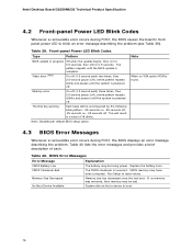
... a device to blink an error message describing the problem (see Table 39). Memory error On-off for 0.5 seconds, then off (1.0 second each . CMOS memory may be losing power. If no VGA option ROM is found. 4.3 BIOS Error Messages Whenever a recoverable error occurs during POST, the BIOS causes the board's front panel power LED to boot. 76 The pattern repeats until the system is complete. Intel Desktop Board D2550MUD2 Technical Product Specification 4.2 Front-panel Power LED Blink Codes Whenever a recoverable error occurs...
... a device to blink an error message describing the problem (see Table 39). Memory error On-off for 0.5 seconds, then off (1.0 second each . CMOS memory may be losing power. If no VGA option ROM is found. 4.3 BIOS Error Messages Whenever a recoverable error occurs during POST, the BIOS causes the board's front panel power LED to boot. 76 The pattern repeats until the system is complete. Intel Desktop Board D2550MUD2 Technical Product Specification 4.2 Front-panel Power LED Blink Codes Whenever a recoverable error occurs...
Technical product specification
Page 77
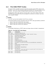
... memory detection PEI phase post MRC execution Recovery Platform DXE driver 0x41 - 0x4F 0x50 - 0x5F 0x60 - 0x6F CPU Initialization (PEI, DXE, SMM) I /O port 80h. Not that critical since consoles should be installed in hexadecimal. Displaying the POST codes requires a PCI bus add-in card, often called a POST card. This code is an unrecoverable error. The POST card can decode the port and display the contents on a medium such as a seven-segment display. Port...
... memory detection PEI phase post MRC execution Recovery Platform DXE driver 0x41 - 0x4F 0x50 - 0x5F 0x60 - 0x6F CPU Initialization (PEI, DXE, SMM) I /O port 80h. Not that critical since consoles should be installed in hexadecimal. Displaying the POST codes requires a PCI bus add-in card, often called a POST card. This code is an unrecoverable error. The POST card can decode the port and display the contents on a medium such as a seven-segment display. Port...


