Product Guide
Page 3
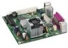
may not be supported without further evaluation by Intel. NOTE Notes call attention to hardware or loss of data. Preface This Product Guide gives information about BIOS error messages B ...PC) for Intel® Desktop Board D201GLY2. Intended Uses All Intel® Desktop Boards are arranged as follows: 1 Desktop Board Features: a summary of this manual: CAUTION Cautions warn the user about how to prevent damage to important information. The suitability of product features 2 Installing and Replacing Desktop Board Components: instructions on how to install the Desktop Board and other...
may not be supported without further evaluation by Intel. NOTE Notes call attention to hardware or loss of data. Preface This Product Guide gives information about BIOS error messages B ...PC) for Intel® Desktop Board D201GLY2. Intended Uses All Intel® Desktop Boards are arranged as follows: 1 Desktop Board Features: a summary of this manual: CAUTION Cautions warn the user about how to prevent damage to important information. The suitability of product features 2 Installing and Replacing Desktop Board Components: instructions on how to install the Desktop Board and other...
Product Guide
Page 5
...USB 21 Wake from PS/2 Keyboard/Mouse 21 PME# Wakeup Support 21 Battery ...21 Real-Time Clock 21 2 Installing and Replacing Desktop Board Components Before You Begin 23 Installation Precautions 24 Prevent Power Supply Overload 24 Observe Safety and Regulatory Requirements 24 Installing the I/O ...Shield 25 Installing and Removing the Desktop Board 26 Installing and Removing Memory 27 Installing DIMMs 27 Removing DIMMs 29 Connecting the IDE Cable 29 Connecting the Serial ATA ...
...USB 21 Wake from PS/2 Keyboard/Mouse 21 PME# Wakeup Support 21 Battery ...21 Real-Time Clock 21 2 Installing and Replacing Desktop Board Components Before You Begin 23 Installation Precautions 24 Prevent Power Supply Overload 24 Observe Safety and Regulatory Requirements 24 Installing the I/O ...Shield 25 Installing and Removing the Desktop Board 26 Installing and Removing Memory 27 Installing DIMMs 27 Removing DIMMs 29 Connecting the IDE Cable 29 Connecting the Serial ATA ...
Product Guide
Page 6
...35 Connecting Supply Power Cables 36 Setting the Desktop Board Jumpers 37 Front Panel Audio Header/Jumper Block 37 BIOS Configuration Jumper 38 Clearing Passwords 39 Replacing the Battery 40 3 Updating the BIOS Updating the BIOS with the Intel® Express BIOS Update Utility 45 Updating ... 49 European Union Declaration of Conformity Statement 50 Product Ecology Statements 51 Recycling Considerations 51 Lead-free 2LI/Pb-free 2LI Board 54 Restriction of Hazardous Substances (RoHS 55 European Union RoHS 55 China RoHS 55 EMC Regulations 58 Ensure Electromagnetic Compatibility (EMC...
...35 Connecting Supply Power Cables 36 Setting the Desktop Board Jumpers 37 Front Panel Audio Header/Jumper Block 37 BIOS Configuration Jumper 38 Clearing Passwords 39 Replacing the Battery 40 3 Updating the BIOS Updating the BIOS with the Intel® Express BIOS Update Utility 45 Updating ... 49 European Union Declaration of Conformity Statement 50 Product Ecology Statements 51 Recycling Considerations 51 Lead-free 2LI/Pb-free 2LI Board 54 Restriction of Hazardous Substances (RoHS 55 European Union RoHS 55 China RoHS 55 EMC Regulations 58 Ensure Electromagnetic Compatibility (EMC...
Product Guide
Page 21
PME# Wakeup Support When the PME# signal on how to replace the battery. Desktop Board Features Wake from USB NOTE Wake from USB requires the use of -day clock and 100-year calendar. The battery on the Desktop Board keeps the values in CMOS RAM and the clock current when the computer is ... USB bus activity wakes the computer from an ACPI S1 state. Battery A battery on the Desktop Board keeps the clock current when the computer is asserted, the computer wakes from USB. Real-Time Clock The Desktop Board has a time-of a USB peripheral that supports wake from an ACPI S1 or S5 state...
PME# Wakeup Support When the PME# signal on how to replace the battery. Desktop Board Features Wake from USB NOTE Wake from USB requires the use of -day clock and 100-year calendar. The battery on the Desktop Board keeps the values in CMOS RAM and the clock current when the computer is ... USB bus activity wakes the computer from an ACPI S1 state. Battery A battery on the Desktop Board keeps the clock current when the computer is asserted, the computer wakes from USB. Real-Time Clock The Desktop Board has a time-of a USB peripheral that supports wake from an ACPI S1 or S5 state...
Product Guide
Page 23
2 Installing and Replacing Desktop Board Components This chapter tells you how to: • Install the I/O shield • Install and remove the Desktop Board • Install and remove memory • Connect the IDE cable • Connect the SATA cable • Connect internal headers • Connect chassis fan and power ...
2 Installing and Replacing Desktop Board Components This chapter tells you how to: • Install the I/O shield • Install and remove the Desktop Board • Install and remove memory • Connect the IDE cable • Connect the SATA cable • Connect internal headers • Connect chassis fan and power ...
Product Guide
Page 25
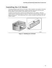
... from the chassis supplier. Figure 5. Installing the I /O shield. Press the shield into place so that it fits tightly and securely. Installing and Replacing Desktop Board Components Installing the I/O Shield The Desktop Board comes with an I /O Shield 25 Place the shield inside the chassis as shown in Figure 5. If the shield does not fit, obtain a properly...
... from the chassis supplier. Figure 5. Installing the I /O shield. Press the shield into place so that it fits tightly and securely. Installing and Replacing Desktop Board Components Installing the I/O Shield The Desktop Board comes with an I /O Shield 25 Place the shield inside the chassis as shown in Figure 5. If the shield does not fit, obtain a properly...
Product Guide
Page 27
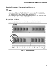
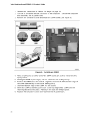
...Presence Detect Specification at: http://www.intel.com/technology/memory/ddr/specs/dda18c32_64_128x72ag_a.pdf The Desktop Board has one 240-pin DDR2 DIMM socket. All the notches should match the DDR2 DIMM. Installing and Replacing Desktop Board Components Installing and Removing Memory NOTE To... be fully compliant with all applicable Intel SDRAM memory specifications, the boards require DIMMs that support the Serial Presence Detect (SPD) data structure...
...Presence Detect Specification at: http://www.intel.com/technology/memory/ddr/specs/dda18c32_64_128x72ag_a.pdf The Desktop Board has one 240-pin DDR2 DIMM socket. All the notches should match the DDR2 DIMM. Installing and Replacing Desktop Board Components Installing and Removing Memory NOTE To... be fully compliant with all applicable Intel SDRAM memory specifications, the boards require DIMMs that support the Serial Presence Detect (SPD) data structure...
Product Guide
Page 28
... Insert the bottom edge of the DIMM until the retaining clips snap into the socket. 8. Make sure the clips are pushed outward to the computer. Intel Desktop Board D201GLY2 Product Guide 1. Turn off the computer and disconnect the AC power cord. 3. Installing a DIMM 4. Align the small notch at either end of..., push down on page 23. 2. Position the DIMM above the socket. Turn off all peripheral devices connected to the open position. 5. Replace the computer's cover and reconnect the AC power cord. 28 Observe the precautions in the socket (see Figure 8).
... Insert the bottom edge of the DIMM until the retaining clips snap into the socket. 8. Make sure the clips are pushed outward to the computer. Intel Desktop Board D201GLY2 Product Guide 1. Turn off the computer and disconnect the AC power cord. 3. Installing a DIMM 4. Align the small notch at either end of..., push down on page 23. 2. Position the DIMM above the socket. Turn off all peripheral devices connected to the open position. 5. Replace the computer's cover and reconnect the AC power cord. 28 Observe the precautions in the socket (see Figure 8).
Product Guide
Page 29
... 29 Attach the cable end with drives using any parts you removed or disconnected to that of the slowest drive. Installing and Replacing Desktop Board Components Removing DIMMs To remove a DIMM, follow these steps: 1. Remove the AC power cord from the socket, and store it... with the two closely spaced connectors (gray and black) to the Desktop Board. Reinstall and reconnect any other IDE transfer protocol are backward compatible with the single connector (blue) to the Intel Desktop Board (Figure 9). 3. Replace the computer's cover and reconnect the AC power cord. The cable supports...
... 29 Attach the cable end with drives using any parts you removed or disconnected to that of the slowest drive. Installing and Replacing Desktop Board Components Removing DIMMs To remove a DIMM, follow these steps: 1. Remove the AC power cord from the socket, and store it... with the two closely spaced connectors (gray and black) to the Desktop Board. Reinstall and reconnect any other IDE transfer protocol are backward compatible with the single connector (blue) to the Intel Desktop Board (Figure 9). 3. Replace the computer's cover and reconnect the AC power cord. The cable supports...
Product Guide
Page 31
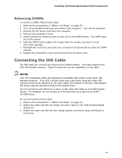
Observe the precautions in "Before You Begin" on the board (Figure 10, A). 3. Connecting the Serial ATA Cable 31 For correct cable function: 1. Figure 10. Attach the cable end without the lock to the desktop board. Attach the locking cable end to the connector on page 23. 2. Installing and Replacing Desktop Board Components Connecting the Serial ATA (SATA) Cable The SATA cable supports the Serial ATA protocol and connects a single drive to the drive (Figure 10, B).
Observe the precautions in "Before You Begin" on the board (Figure 10, A). 3. Connecting the Serial ATA Cable 31 For correct cable function: 1. Figure 10. Attach the cable end without the lock to the desktop board. Attach the locking cable end to the connector on page 23. 2. Installing and Replacing Desktop Board Components Connecting the Serial ATA (SATA) Cable The SATA cable supports the Serial ATA protocol and connects a single drive to the drive (Figure 10, B).
Product Guide
Page 33
... cable. 6. To restore back panel operations, follow these steps: 1. Remove the cover. 4. Install a jumper on pins 5-6 (rear R channel). 6. Replace the cover. 33 Installing and Replacing Desktop Board Components Installing a Front Panel Audio Solution Figure 11, A shows the location of the front panel audio header. Table 4. Turn off the computer and.... Remove the front panel audio cable. 5. Locate the front panel audio header. Turn off all peripheral devices connected to the computer. Replace the cover. Turn off the computer and disconnect the AC power cord. 3.
... cable. 6. To restore back panel operations, follow these steps: 1. Remove the cover. 4. Install a jumper on pins 5-6 (rear R channel). 6. Replace the cover. 33 Installing and Replacing Desktop Board Components Installing a Front Panel Audio Solution Figure 11, A shows the location of the front panel audio header. Table 4. Turn off the computer and.... Remove the front panel audio cable. 5. Locate the front panel audio header. Turn off all peripheral devices connected to the computer. Replace the cover. Turn off the computer and disconnect the AC power cord. 3.
Product Guide
Page 35
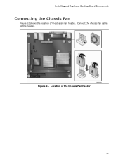
Installing and Replacing Desktop Board Components Connecting the Chassis Fan Figure 12 shows the location of the Chassis Fan Header 35 Location of the chassis fan header. Connect the chassis fan cable to this header. Figure 12.
Installing and Replacing Desktop Board Components Connecting the Chassis Fan Figure 12 shows the location of the Chassis Fan Header 35 Location of the chassis fan header. Connect the chassis fan cable to this header. Figure 12.
Product Guide
Page 37
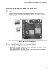
...: • With jumpers installed, the audio line out and mic-in signals are routed to the back panel audio connectors (see Table 4). 37 Installing and Replacing Desktop Board Components Setting the Desktop Board Jumpers NOTE Always turn off the power and unplug the power cord from the computer before changing a jumper. Figure 14.
...: • With jumpers installed, the audio line out and mic-in signals are routed to the back panel audio connectors (see Table 4). 37 Installing and Replacing Desktop Board Components Setting the Desktop Board Jumpers NOTE Always turn off the power and unplug the power cord from the computer before changing a jumper. Figure 14.
Product Guide
Page 39
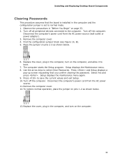
Installing and Replacing Desktop Board Components Clearing Passwords This procedure assumes that you confirm clearing the ...shown below . 13. The computer starts the Setup program. Turn off the computer. Remove the computer cover. 12. Replace the cover, plug in the computer, and turn on the computer, and allow it to boot. 7. Observe the precautions...menu. 8. Press and Setup displays a pop-up screen requesting that the board is installed in the computer and the configuration jumper is set to select Clear Passwords. Replace the cover, plug in "Before You Begin" on the computer. 39...
Installing and Replacing Desktop Board Components Clearing Passwords This procedure assumes that you confirm clearing the ...shown below . 13. The computer starts the Setup program. Turn off the computer. Remove the computer cover. 12. Replace the cover, plug in the computer, and turn on the computer, and allow it to boot. 7. Observe the precautions...menu. 8. Press and Setup displays a pop-up screen requesting that the board is installed in the computer and the configuration jumper is set to select Clear Passwords. Replace the cover, plug in "Before You Begin" on the computer. 39...
Product Guide
Page 40
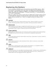
...;tts med felaktig batterityp. Käytetyt paristot on page 44 shows the location of the battery. When the computer is replaced with local environmental regulations. CAUTION Risk of three years. FORHOLDSREGEL Eksplosionsfare, hvis batteriet erstattes med et batteri af en forkert...248;r kastes i henhold til gjeldende miljølovgivning. VARO Räjähdysvaara, jos pariston tyyppi on mahdollista. VIKTIGT! Intel Desktop Board D201GLY2 Product Guide Replacing the Battery A coin-cell battery (CR2032) powers the real-time clock and CMOS memory. When the computer is accurate ...
...;tts med felaktig batterityp. Käytetyt paristot on page 44 shows the location of the battery. When the computer is replaced with local environmental regulations. CAUTION Risk of three years. FORHOLDSREGEL Eksplosionsfare, hvis batteriet erstattes med et batteri af en forkert...248;r kastes i henhold til gjeldende miljølovgivning. VARO Räjähdysvaara, jos pariston tyyppi on mahdollista. VIKTIGT! Intel Desktop Board D201GLY2 Product Guide Replacing the Battery A coin-cell battery (CR2032) powers the real-time clock and CMOS memory. When the computer is accurate ...
Product Guide
Page 43
Installing and Replacing Desktop Board Components 43
Installing and Replacing Desktop Board Components 43
Product Guide
Page 44
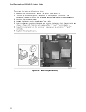
Figure 15. Remove the computer cover. 4. Note the orientation of the "+" and "-" on the board (see page 23). 2. Replace the computer cover. Push the battery retention clip aside and remove the battery from the AC power source (wall outlet or power adapter). 3. Observe the ... Begin" (see Figure 15). 5. Turn off all peripheral devices connected to orient the "+" and "-" correctly. 7. Locate the battery on the battery. 6. Removing the Battery 44 Intel Desktop Board D201GLY2 Product Guide To replace the battery, follow these steps: 1.
Figure 15. Remove the computer cover. 4. Note the orientation of the "+" and "-" on the board (see page 23). 2. Replace the computer cover. Push the battery retention clip aside and remove the battery from the AC power source (wall outlet or power adapter). 3. Observe the ... Begin" (see Figure 15). 5. Turn off all peripheral devices connected to orient the "+" and "-" correctly. 7. Locate the battery on the battery. 6. Removing the Battery 44 Intel Desktop Board D201GLY2 Product Guide To replace the battery, follow these steps: 1.
Product Guide
Page 49
...the statement below or an equivalent statement is insufficient space on this Desktop Board to be permanently and legibly marked on the chassis near the battery. Related Links For information about replacing the battery, go to page 40. 49 Part 1: General Requirements... (USA and Canada) Information Technology Equipment - A suitable caution label is replaced with Desktop Board D201GLY2. B Regulatory Compliance This appendix contains the following regulatory compliance information for replacing and disposing of the Lithium ion coin cell battery. Safety - Batteries should be...
...the statement below or an equivalent statement is insufficient space on this Desktop Board to be permanently and legibly marked on the chassis near the battery. Related Links For information about replacing the battery, go to page 40. 49 Part 1: General Requirements... (USA and Canada) Information Technology Equipment - A suitable caution label is replaced with Desktop Board D201GLY2. B Regulatory Compliance This appendix contains the following regulatory compliance information for replacing and disposing of the Lithium ion coin cell battery. Safety - Batteries should be...


