Product Guide
Page 5
... 10 Desktop Board Components 11 Processor ...13 Main Memory...13 Chipset...14 Graphics Subsystem 14 Audio Subsystem 14 Input/Output (I/O) Controller 15 LAN Subsystem 15 LAN Subsystem Software 16 RJ-45 LAN Connector LEDs 16 Hi-Speed USB 2.0 Support 17 Enhanced IDE Interface 17 Serial ATA...17 Expandability...17 BIOS ...17 IDE Auto Configuration 18 PCI Auto Configuration 18 Security Passwords 18 Power Management Features 18 ACPI ...19 Hardware Support 19 Power Connectors 19 Fan Headers 19 +5 V Standby Power Indicator LED 19 LAN Wake Capabilities 20 Wake from USB 21 Wake from...
... 10 Desktop Board Components 11 Processor ...13 Main Memory...13 Chipset...14 Graphics Subsystem 14 Audio Subsystem 14 Input/Output (I/O) Controller 15 LAN Subsystem 15 LAN Subsystem Software 16 RJ-45 LAN Connector LEDs 16 Hi-Speed USB 2.0 Support 17 Enhanced IDE Interface 17 Serial ATA...17 Expandability...17 BIOS ...17 IDE Auto Configuration 18 PCI Auto Configuration 18 Security Passwords 18 Power Management Features 18 ACPI ...19 Hardware Support 19 Power Connectors 19 Fan Headers 19 +5 V Standby Power Indicator LED 19 LAN Wake Capabilities 20 Wake from USB 21 Wake from...
Product Guide
Page 6
...the Front Panel Header 34 Connecting the Chassis Fan 35 Connecting Supply Power Cables 36 Setting the Desktop Board Jumpers 37 Front Panel Audio Header/Jumper Block 37 BIOS Configuration Jumper 38 Clearing Passwords 39 Replacing the Battery 40 3 Updating the BIOS Updating the BIOS with the Intel® Express BIOS Update Utility 45 Updating the BIOS with the Iflash Memory Update Utility 45 Obtaining the BIOS Update File 45 Updating the BIOS with the Iflash Memory Update Utility 46 Recovering the BIOS 46 A BIOS Error Messages BIOS Front-panel Power LED Codes 47 BIOS Error Messages...
...the Front Panel Header 34 Connecting the Chassis Fan 35 Connecting Supply Power Cables 36 Setting the Desktop Board Jumpers 37 Front Panel Audio Header/Jumper Block 37 BIOS Configuration Jumper 38 Clearing Passwords 39 Replacing the Battery 40 3 Updating the BIOS Updating the BIOS with the Intel® Express BIOS Update Utility 45 Updating the BIOS with the Iflash Memory Update Utility 45 Obtaining the BIOS Update File 45 Updating the BIOS with the Iflash Memory Update Utility 46 Recovering the BIOS 46 A BIOS Error Messages BIOS Front-panel Power LED Codes 47 BIOS Error Messages...
Product Guide
Page 7
... LEDs 16 4. Hi-Speed USB 2.0 Header Signal Names 34 6. China RoHS Environmentally Friendly Use Period Mark 56 14. Back Panel Audio Connectors 15 3. LAN Connector LEDs 16 4. Use DDR2 DIMMs 27 8. Installing a DIMM 28 9. Connecting the IDE Cable 30 10. Internal Headers 32 12. Location of the Standby Power Indicator 20 5. Connecting a 2 x 10 or 2 x 12 Power Supply Cable 36 14. Removing the Battery 44 16. Desktop Boards D201GLY2 Components 12 3. Front Panel Audio Header/Jumper Block 38 8. Jumper Settings for the BIOS Setup Program Modes 38 9. Front-panel Power LED...
... LEDs 16 4. Hi-Speed USB 2.0 Header Signal Names 34 6. China RoHS Environmentally Friendly Use Period Mark 56 14. Back Panel Audio Connectors 15 3. LAN Connector LEDs 16 4. Use DDR2 DIMMs 27 8. Installing a DIMM 28 9. Connecting the IDE Cable 30 10. Internal Headers 32 12. Location of the Standby Power Indicator 20 5. Connecting a 2 x 10 or 2 x 12 Power Supply Cable 36 14. Removing the Battery 44 16. Desktop Boards D201GLY2 Components 12 3. Front Panel Audio Header/Jumper Block 38 8. Jumper Settings for the BIOS Setup Program Modes 38 9. Front-panel Power LED...
Product Guide
Page 9
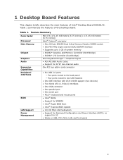
... panel ― Four ports routed to two USB headers • One IDE interface with ATA-100/66 support (two devices) • Two Serial ATA (1.5 Gb/s) interfaces • One VGA connector • One parallel port • One serial port • PS/2* keyboard and mouse ports • Intel® BIOS • Support for SMBIOS • Intel® Rapid BIOS Boot • Intel® Express BIOS Update LAN Support • 10/100 Mb/s LAN Subsystem Power Management • Support for S3 • Wake on USB, PCI...
... panel ― Four ports routed to two USB headers • One IDE interface with ATA-100/66 support (two devices) • Two Serial ATA (1.5 Gb/s) interfaces • One VGA connector • One parallel port • One serial port • PS/2* keyboard and mouse ports • Intel® BIOS • Support for SMBIOS • Intel® Rapid BIOS Boot • Intel® Express BIOS Update LAN Support • 10/100 Mb/s LAN Subsystem Power Management • Support for S3 • Wake on USB, PCI...
Product Guide
Page 12
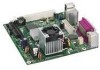
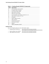
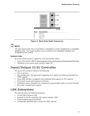
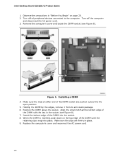
... Description PCI bus add-in card connector Hi-speed USB 2.0 headers Front panel audio header Back panel connectors Rear fan (3-pin) header 12 V processor core voltage connector (2 x 2) Main power connector (2 x 10) Processor DDR 2 DIMM connector IDE connector Serial ATA connectors Front panel header Battery BIOS configuration jumper Related Links: Go to the following links for more information about: • Desktop Board D201GLY2 • Audio software and utilities • LAN software and drivers http://www.intel.com/design/motherbd http://support.intel.com/support/motherboards/desktop...
... Description PCI bus add-in card connector Hi-speed USB 2.0 headers Front panel audio header Back panel connectors Rear fan (3-pin) header 12 V processor core voltage connector (2 x 2) Main power connector (2 x 10) Processor DDR 2 DIMM connector IDE connector Serial ATA connectors Front panel header Battery BIOS configuration jumper Related Links: Go to the following links for more information about: • Desktop Board D201GLY2 • Audio software and utilities • LAN software and drivers http://www.intel.com/design/motherbd http://support.intel.com/support/motherboards/desktop...
Product Guide
Page 13
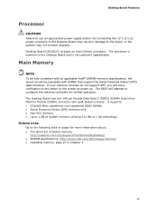
... configure the memory controller for more information about: • The latest list of tested memory, http://support.intel.com/support/motherboards/desktop/ • SDRAM specifications, http://www.intel.com/technology/memory/ • Installing memory, page 27 in Chapter 2 13 Main Memory NOTE To be fully compliant with all applicable Intel® SDRAM memory specifications, the board should be populated with gold-plated contacts. Desktop Board D201GLY2 includes an Intel Celeron processor. The processor is not customer upgradeable. The BIOS...
... configure the memory controller for more information about: • The latest list of tested memory, http://support.intel.com/support/motherboards/desktop/ • SDRAM specifications, http://www.intel.com/technology/memory/ • Installing memory, page 27 in Chapter 2 13 Main Memory NOTE To be fully compliant with all applicable Intel® SDRAM memory specifications, the board should be populated with gold-plated contacts. Desktop Board D201GLY2 includes an Intel Celeron processor. The processor is not customer upgradeable. The BIOS...
Product Guide
Page 14
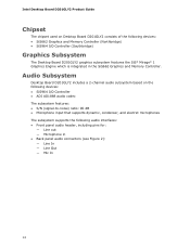
Intel Desktop Board D201GLY2 Product Guide Chipset The chipset used on the following audio interfaces: • Front panel audio header, including pins for: ― Line out ― Microphone in the SiS662 Graphics and Memory Controller. Audio Subsystem Desktop Board D201GLY2 includes a 2-channel audio subsystem based on Desktop Board D201GLY2 consists of the following devices: • SiS662 Graphics and Memory Controller (Northbridge) • SiS964 I /O Controller • ADI AD1888 audio codec The subsystem features: • S/N (signal-to-noise) ratio: 90 dB...
Intel Desktop Board D201GLY2 Product Guide Chipset The chipset used on the following audio interfaces: • Front panel audio header, including pins for: ― Line out ― Microphone in the SiS662 Graphics and Memory Controller. Audio Subsystem Desktop Board D201GLY2 includes a 2-channel audio subsystem based on Desktop Board D201GLY2 consists of the following devices: • SiS662 Graphics and Memory Controller (Northbridge) • SiS964 I /O Controller • ADI AD1888 audio codec The subsystem features: • S/N (signal-to-noise) ratio: 90 dB...
Product Guide
Page 15
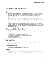
... utilities http://support.intel.com/support/motherboards/desktop/ • Installing a front panel audio solution (page 33) Input/Output (I/O) Controller The super I/O controller features the following: • One serial port • One parallel port with Extended Capabilities Port (ECP) and Enhanced Parallel Port (EPP) support • Serial IRQ interface compatible with serialized IRQ support for PCI systems • PS/2-style mouse and keyboard interfaces • Intelligent power management, including a programmable wake up event interface • PCI power management support LAN...
... utilities http://support.intel.com/support/motherboards/desktop/ • Installing a front panel audio solution (page 33) Input/Output (I/O) Controller The super I/O controller features the following: • One serial port • One parallel port with Extended Capabilities Port (ECP) and Enhanced Parallel Port (EPP) support • Serial IRQ interface compatible with serialized IRQ support for PCI systems • PS/2-style mouse and keyboard interfaces • Intelligent power management, including a programmable wake up event interface • PCI power management support LAN...
Product Guide
Page 17
... and drivers that meets the requirements for a full-speed USB device. Enhanced IDE Interface The IDE interface handles the exchange of information between the processor and peripheral devices such as CD-ROM or DVD drives) • Older PIO Mode devices • Ultra DMA-33/66/100 modes Serial ATA The Desktop Board supports two Serial ATA channels (1.5 Gb/s), connecting one PCI add-in the BIOS reverts all USB 2.0 ports to two internal USB 2.0 headers). Expandability The Desktop Board supports one device per channel...
... and drivers that meets the requirements for a full-speed USB device. Enhanced IDE Interface The IDE interface handles the exchange of information between the processor and peripheral devices such as CD-ROM or DVD drives) • Older PIO Mode devices • Ultra DMA-33/66/100 modes Serial ATA The Desktop Board supports two Serial ATA channels (1.5 Gb/s), connecting one PCI add-in the BIOS reverts all USB 2.0 ports to two internal USB 2.0 headers). Expandability The Desktop Board supports one device per channel...
Product Guide
Page 18
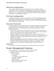
... (ACPI) • Hardware support: ― Power connectors ― Fan headers ― +5 V standby power indicator LED ― LAN Wake capabilities ― Wake from USB ― Wake from PS/2 keyboard/mouse ― PME# wakeup support 18 You do not need to view and change all Setup options. Security Passwords The BIOS includes security features that add-in the BIOS Setup program. Related Links: For instructions on resetting the password, see Clearing Passwords on whether the supervisor or user password was entered. • Setting a user password...
... (ACPI) • Hardware support: ― Power connectors ― Fan headers ― +5 V standby power indicator LED ― LAN Wake capabilities ― Wake from USB ― Wake from PS/2 keyboard/mouse ― PME# wakeup support 18 You do not need to view and change all Setup options. Security Passwords The BIOS includes security features that add-in the BIOS Setup program. Related Links: For instructions on resetting the password, see Clearing Passwords on whether the supervisor or user password was entered. • Setting a user password...
Product Guide
Page 19
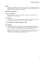
Hardware Support Power Connectors The Desktop Board has two power connectors. Fan Headers The Desktop Board has a 3-pin processor fan header and a 3-pin chassis fan header. The Desktop Board's standby power indicator, shown in Figure 4, is lit when there is still lit, disconnect the power cord before installing or removing any attached devices. Failure to be off and the standby power indicator is standby power to the board. This includes the DIMM socket and the PCI bus connector, even though the computer appears to do...
Hardware Support Power Connectors The Desktop Board has two power connectors. Fan Headers The Desktop Board has a 3-pin processor fan header and a 3-pin chassis fan header. The Desktop Board's standby power indicator, shown in Figure 4, is lit when there is still lit, disconnect the power cord before installing or removing any attached devices. Failure to be off and the standby power indicator is standby power to the board. This includes the DIMM socket and the PCI bus connector, even though the computer appears to do...
Product Guide
Page 23
..., such as model, serial numbers, installed options, and configuration information. • Electrostatic discharge (ESD) can damage components. Follow these guidelines before performing any procedures can continue to : • Install the I/O shield • Install and remove the Desktop Board • Install and remove memory • Connect the IDE cable • Connect the SATA cable • Connect internal headers • Connect chassis fan and power supply cables • Set the BIOS configuration and audio jumpers • Clear passwords • Replace the battery Before You Begin...
..., such as model, serial numbers, installed options, and configuration information. • Electrostatic discharge (ESD) can damage components. Follow these guidelines before performing any procedures can continue to : • Install the I/O shield • Install and remove the Desktop Board • Install and remove memory • Connect the IDE cable • Connect the SATA cable • Connect internal headers • Connect chassis fan and power supply cables • Set the BIOS configuration and audio jumpers • Clear passwords • Replace the battery Before You Begin...
Product Guide
Page 28
... and locate the DIMM socket (see Figure 8). 7. Turn off the computer and disconnect the AC power cord. 3. Holding the DIMM by the edges, remove it from its anti-static package. 6. Align the small notch at either end of the DIMM until the retaining clips snap into the socket. 8. Installing a DIMM 4. Position the DIMM above the socket. Intel Desktop Board D201GLY2 Product Guide 1.
... and locate the DIMM socket (see Figure 8). 7. Turn off the computer and disconnect the AC power cord. 3. Holding the DIMM by the edges, remove it from its anti-static package. 6. Align the small notch at either end of the DIMM until the retaining clips snap into the socket. 8. Installing a DIMM 4. Position the DIMM above the socket. Intel Desktop Board D201GLY2 Product Guide 1.
Product Guide
Page 29
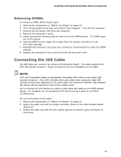
... transfer rate between the drives may be reduced to an ATAPI CD-ROM drive. Attach the cable end with the single connector (blue) to the Desktop Board. Do not connect an ATA device as a slave on page 23. 2. For example, do not connect an ATA hard drive as an ATAPI master device. Installing and Replacing Desktop Board Components Removing DIMMs To remove a DIMM, follow these steps: 1. Turn off the computer. 3.
... transfer rate between the drives may be reduced to an ATAPI CD-ROM drive. Attach the cable end with the single connector (blue) to the Desktop Board. Do not connect an ATA device as a slave on page 23. 2. For example, do not connect an ATA hard drive as an ATAPI master device. Installing and Replacing Desktop Board Components Removing DIMMs To remove a DIMM, follow these steps: 1. Turn off the computer. 3.
Product Guide
Page 33
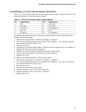
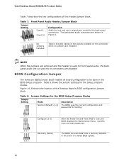
... audio cable. 6. Connect the audio cable to disable the back panel audio connectors. 5. Remove the front panel audio cable. 5. Front Panel Audio Header Signal Names Pin Signal Name 1 MIC 3 MIC-BIAS 5 FP_OUT_R 7 AUD_5V 9 FP_OUT_L Pin Signal Name 2 AUD_GND 4 AUD_GND 6 FP_RETURN_R 8 KEY 10 FP_RETURN_L To install a cable that connects a front panel audio solution to the front panel audio header, follow these steps: 1. Replace the cover. Turn off all peripheral devices connected to the computer. Remove the cover. 4. Installing and Replacing Desktop Board...
... audio cable. 6. Connect the audio cable to disable the back panel audio connectors. 5. Remove the front panel audio cable. 5. Front Panel Audio Header Signal Names Pin Signal Name 1 MIC 3 MIC-BIAS 5 FP_OUT_R 7 AUD_5V 9 FP_OUT_L Pin Signal Name 2 AUD_GND 4 AUD_GND 6 FP_RETURN_R 8 KEY 10 FP_RETURN_L To install a cable that connects a front panel audio solution to the front panel audio header, follow these steps: 1. Replace the cover. Turn off all peripheral devices connected to the computer. Remove the cover. 4. Installing and Replacing Desktop Board...
Product Guide
Page 38
... the BIOS Setup Program Modes Jumper Setting Mode Normal (default) (1-2) Description The BIOS uses the current configuration and passwords for the Setup program modes. Recovery (None) The BIOS recovers data from a recovery diskette in the BIOS Setup program. Table 8 shows the jumper settings for booting. Table 8. The back panel audio connectors are routed to the back panel connectors. NOTE When the jumpers are disabled. BIOS Configuration Jumper The three-pin BIOS jumper block enables all board configuration to clear passwords. Use this header is used for front panel audio...
... the BIOS Setup Program Modes Jumper Setting Mode Normal (default) (1-2) Description The BIOS uses the current configuration and passwords for the Setup program modes. Recovery (None) The BIOS recovers data from a recovery diskette in the BIOS Setup program. Table 8 shows the jumper settings for booting. Table 8. The back panel audio connectors are routed to the back panel connectors. NOTE When the jumpers are disabled. BIOS Configuration Jumper The three-pin BIOS jumper block enables all board configuration to clear passwords. Use this header is used for front panel audio...
Product Guide
Page 39
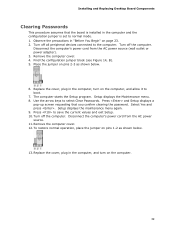
... that the board is installed in the computer, turn on page 23. 2. Installing and Replacing Desktop Board Components Clearing Passwords This procedure assumes that you confirm clearing the password. Replace the cover, plug in the computer and the configuration jumper is set to the computer. Setup displays the maintenance menu again. 9. The computer starts the Setup program. Remove the computer cover. 4. Place the jumper on the computer, and allow it to boot. 7. Disconnect the...
... that the board is installed in the computer, turn on page 23. 2. Installing and Replacing Desktop Board Components Clearing Passwords This procedure assumes that you confirm clearing the password. Replace the cover, plug in the computer and the configuration jumper is set to the computer. Setup displays the maintenance menu again. 9. The computer starts the Setup program. Remove the computer cover. 4. Place the jumper on the computer, and allow it to boot. 7. Disconnect the...
Product Guide
Page 45
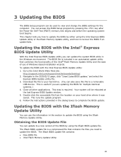
... the BIOS Update File You can access the BIOS Setup program by using the Intel Express BIOS Update utility or the Iflash Memory Update utility, and how to a removable USB device. Navigate to complete the BIOS update. Follow the instructions provided in this file to recover the BIOS if an update fails. Double-click the executable file from the location on your hard drive. (You can update the system BIOS while in the Windows environment. To update the BIOS with the Intel Express BIOS Update utility: 1. You can update...
... the BIOS Update File You can access the BIOS Setup program by using the Intel Express BIOS Update utility or the Iflash Memory Update utility, and how to a removable USB device. Navigate to complete the BIOS update. Follow the instructions provided in this file to recover the BIOS if an update fails. Double-click the executable file from the location on your hard drive. (You can update the system BIOS while in the Windows environment. To update the BIOS with the Intel Express BIOS Update utility: 1. You can update...
Product Guide
Page 46
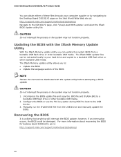
... the USB device and manually update the BIOS. Configure the BIOS or use the F10 key option during POST to boot to the D201GLY2 page, click "[view] Latest BIOS updates," and select the Iflash BIOS Update utility file. Recovering the BIOS It is unlikely that anything will interrupt the BIOS update; Intel Desktop Board D201GLY2 Product Guide You can obtain either of the BIOS NOTE Review the instructions distributed with the Iflash Memory Update Utility With the Iflash Memory update utility you to a bootable USB flash drive...
... the USB device and manually update the BIOS. Configure the BIOS or use the F10 key option during POST to boot to the D201GLY2 page, click "[view] Latest BIOS updates," and select the Iflash BIOS Update utility file. Recovering the BIOS It is unlikely that anything will interrupt the BIOS update; Intel Desktop Board D201GLY2 Product Guide You can obtain either of the BIOS NOTE Review the instructions distributed with the Iflash Memory Update Utility With the Iflash Memory update utility you to a bootable USB flash drive...
Product Guide
Page 47
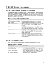
... pause (off) between on-off blink pattern; Table 10. If no memory was removed, then memory may have been corrupted. Table 9. The CMOS memory may be losing power. In addition, whenever a recoverable error occurs during POST, the BIOS causes the front-panel power LED to reset values. Memory size has decreased since the last boot. repeat entire pattern (three on-off blinks and 3-second pause) until...
... pause (off) between on-off blink pattern; Table 10. If no memory was removed, then memory may have been corrupted. Table 9. The CMOS memory may be losing power. In addition, whenever a recoverable error occurs during POST, the BIOS causes the front-panel power LED to reset values. Memory size has decreased since the last boot. repeat entire pattern (three on-off blinks and 3-second pause) until...


