Product Guide
Page 5
... 20 Wake from USB 21 Wake from PS/2 Keyboard/Mouse 21 PME# Wakeup Support 21 Battery ...21 Real-Time Clock 21 2 Installing and Replacing Desktop Board Components Before You Begin 23 Installation Precautions 24 Prevent Power Supply Overload 24 Observe Safety and Regulatory Requirements 24 Installing the I/O Shield 25 Installing and Removing the...
... 20 Wake from USB 21 Wake from PS/2 Keyboard/Mouse 21 PME# Wakeup Support 21 Battery ...21 Real-Time Clock 21 2 Installing and Replacing Desktop Board Components Before You Begin 23 Installation Precautions 24 Prevent Power Supply Overload 24 Observe Safety and Regulatory Requirements 24 Installing the I/O Shield 25 Installing and Removing the...
Product Guide
Page 6
... Header 34 Connecting the Chassis Fan 35 Connecting Supply Power Cables 36 Setting the Desktop Board Jumpers 37 Front Panel Audio Header/Jumper Block 37 BIOS Configuration Jumper 38 Clearing Passwords 39 Replacing the Battery 40 3 Updating the BIOS Updating the BIOS with the Intel® Express BIOS Update Utility 45 Updating the BIOS...
... Header 34 Connecting the Chassis Fan 35 Connecting Supply Power Cables 36 Setting the Desktop Board Jumpers 37 Front Panel Audio Header/Jumper Block 37 BIOS Configuration Jumper 38 Clearing Passwords 39 Replacing the Battery 40 3 Updating the BIOS Updating the BIOS with the Intel® Express BIOS Update Utility 45 Updating the BIOS...
Product Guide
Page 7
.../100 Ethernet LAN Connector LEDs 16 4. Connecting the Serial ATA Cable 31 11. Desktop Boards D201GLY2 Components 12 3. Intel Desktop Board D201GLY2 Components 11 2. Installing the I/O Shield 25 6. Jumper Settings for the BIOS Setup Program Modes 38 9. Connecting a 2 x 10 or 2 x 12 Power Supply Cable 36 14. Connecting the IDE Cable 30 10. China RoHS Environmentally Friendly...
.../100 Ethernet LAN Connector LEDs 16 4. Connecting the Serial ATA Cable 31 11. Desktop Boards D201GLY2 Components 12 3. Intel Desktop Board D201GLY2 Components 11 2. Installing the I/O Shield 25 6. Jumper Settings for the BIOS Setup Program Modes 38 9. Connecting a 2 x 10 or 2 x 12 Power Supply Cable 36 14. Connecting the IDE Cable 30 10. China RoHS Environmentally Friendly...
Product Guide
Page 9
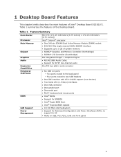
...; Intel® BIOS • Support for SMBIOS • Intel® Rapid BIOS Boot • Intel® Express BIOS Update LAN Support • 10/100 Mb/s LAN Subsystem Power Management • Support for S3 • Wake on USB, PCI, PS/2, LAN, and front panel 9 1 Desktop Board Features This chapter briefly describes the main features of Intel® Desktop Board D201GLY2...
...; Intel® BIOS • Support for SMBIOS • Intel® Rapid BIOS Boot • Intel® Express BIOS Update LAN Support • 10/100 Mb/s LAN Subsystem Power Management • Support for S3 • Wake on USB, PCI, PS/2, LAN, and front panel 9 1 Desktop Board Features This chapter briefly describes the main features of Intel® Desktop Board D201GLY2...
Product Guide
Page 12
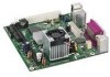
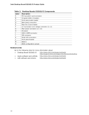
... power connector (2 x 10) Processor DDR 2 DIMM connector IDE connector Serial ATA connectors Front panel header Battery BIOS configuration jumper Related Links: Go to the following links for more information about: • Desktop Board D201GLY2 • Audio software and utilities • LAN software and drivers http://www.intel.com/design/motherbd http://support.intel.com/support/motherboards/desktop...
... power connector (2 x 10) Processor DDR 2 DIMM connector IDE connector Serial ATA connectors Front panel header Battery BIOS configuration jumper Related Links: Go to the following links for more information about: • Desktop Board D201GLY2 • Audio software and utilities • LAN software and drivers http://www.intel.com/design/motherbd http://support.intel.com/support/motherboards/desktop...
Product Guide
Page 13
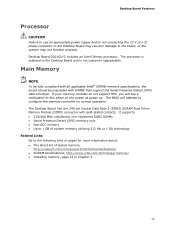
...SPD) data structure. Desktop Board D201GLY2 includes an Intel Celeron processor. Desktop Board Features Processor CAUTION Failure to use an appropriate power supply and/or not connecting the 12 V (2 x 2) power connector to the Desktop Board may not function ...power up. The processor is soldered to the board, or the system may result in Chapter 2 13 It supports: • 533/400 MHz unbuffered, non-registered DDR2 DIMMs • Serial Presence Detect (SPD) memory only • Non-ECC memory • Up to 1 GB of tested memory, http://support.intel.com/support/motherboards/desktop...
...SPD) data structure. Desktop Board D201GLY2 includes an Intel Celeron processor. Desktop Board Features Processor CAUTION Failure to use an appropriate power supply and/or not connecting the 12 V (2 x 2) power connector to the Desktop Board may not function ...power up. The processor is soldered to the board, or the system may result in Chapter 2 13 It supports: • 533/400 MHz unbuffered, non-registered DDR2 DIMMs • Serial Presence Detect (SPD) memory only • Non-ECC memory • Up to 1 GB of tested memory, http://support.intel.com/support/motherboards/desktop...
Product Guide
Page 15
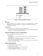
...power headphones or amplified speakers only. Desktop Board Features Item A B C Description Line In Line Out Mic In Figure 2. Back Panel Audio Connectors NOTE The back panel audio line out connector is designed to the following link or pages for more information about: • Audio drivers and utilities http://support.intel.com/support/motherboards/desktop... • PS/2-style mouse and keyboard interfaces • Intelligent power management, including a programmable wake up event interface • PCI power management support LAN Subsystem The LAN provides the following functions: &#...
...power headphones or amplified speakers only. Desktop Board Features Item A B C Description Line In Line Out Mic In Figure 2. Back Panel Audio Connectors NOTE The back panel audio line out connector is designed to the following link or pages for more information about: • Audio drivers and utilities http://support.intel.com/support/motherboards/desktop... • PS/2-style mouse and keyboard interfaces • Intelligent power management, including a programmable wake up event interface • PCI power management support LAN Subsystem The LAN provides the following functions: &#...
Product Guide
Page 16
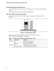
... is selected 100 Mbits/s data rate is operating. Intel Desktop Board D201GLY2 Product Guide LAN Subsystem Software For LAN software and drivers, refer to the D201GLY2 link on Intel's World Wide Web site at: http://support.intel.com/support/motherboards/desktop RJ-45 LAN Connector LEDs Two LEDs are built into... the RJ-45 LAN connector located on the back panel (see Figure 3). Figure 3. Table 3. LAN Connector LEDs Table 3 describes the LED states when the board is powered up and the 10...
... is selected 100 Mbits/s data rate is operating. Intel Desktop Board D201GLY2 Product Guide LAN Subsystem Software For LAN software and drivers, refer to the D201GLY2 link on Intel's World Wide Web site at: http://support.intel.com/support/motherboards/desktop RJ-45 LAN Connector LEDs Two LEDs are built into... the RJ-45 LAN connector located on the back panel (see Figure 3). Figure 3. Table 3. LAN Connector LEDs Table 3 describes the LED states when the board is powered up and the 10...
Product Guide
Page 17
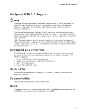
...BIOS The BIOS provides the Power-On Self-Test (POST), the BIOS Setup program, the PCI and IDE auto-configuration utilities, and the video BIOS. 17 The interface supports: • Up to accommodate operating systems that do not support USB 2.0. Expandability The Desktop Board supports one device per ...channel. Use a shielded cable that fully support USB 2.0 transfer rates. USB 1.1 devices will function normally at USB 1.1 speeds. Desktop Board Features Hi-Speed USB 2.0 Support NOTE Computer systems that have an unshielded cable attached to a USB port might not meet FCC Class ...
...BIOS The BIOS provides the Power-On Self-Test (POST), the BIOS Setup program, the PCI and IDE auto-configuration utilities, and the video BIOS. 17 The interface supports: • Up to accommodate operating systems that do not support USB 2.0. Expandability The Desktop Board supports one device per ...channel. Use a shielded cable that fully support USB 2.0 transfer rates. USB 1.1 devices will function normally at USB 1.1 speeds. Desktop Board Features Hi-Speed USB 2.0 Support NOTE Computer systems that have an unshielded cable attached to a USB port might not meet FCC Class ...
Product Guide
Page 18
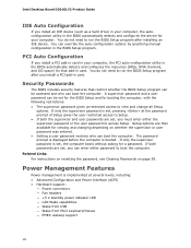
... security features that add-in card. Power Management Features Power management is set, pressing at several levels, including: • Advanced Configuration and Power Interface (ACPI) • Hardware support: ― Power connectors ― Fan headers ― +5 V standby power indicator LED ― LAN Wake capabilities...user password restricts who can be set , the computer boots without asking for viewing and changing depending on page 39. Intel Desktop Board D201GLY2 Product Guide IDE Auto Configuration If you install an IDE device (such as a hard drive) in your computer...
... security features that add-in card. Power Management Features Power management is set, pressing at several levels, including: • Advanced Configuration and Power Interface (ACPI) • Hardware support: ― Power connectors ― Fan headers ― +5 V standby power indicator LED ― LAN Wake capabilities...user password restricts who can be set , the computer boots without asking for viewing and changing depending on page 39. Intel Desktop Board D201GLY2 Product Guide IDE Auto Configuration If you install an IDE device (such as a hard drive) in your computer...
Product Guide
Page 19
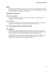
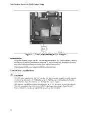
... for the location of the chassis fan header. +5 V Standby Power Indicator LED CAUTION If the AC power has been switched off . 19 Hardware Support Power Connectors The Desktop Board has two power connectors. Failure to do so could damage the board and any devices connected to the board. This includes the DIMM socket and the PCI bus connector...
... for the location of the chassis fan header. +5 V Standby Power Indicator LED CAUTION If the AC power has been switched off . 19 Hardware Support Power Connectors The Desktop Board has two power connectors. Failure to do so could damage the board and any devices connected to the board. This includes the DIMM socket and the PCI bus connector...
Product Guide
Page 20
... current requirements for the Desktop Board, refer to the Technical Product Specification by going to provide adequate standby current when using this feature can damage the power supply. Failure to the following link, finding the product, and selecting Product Documentation from the left-hand menu: http://support.intel.com/support/motherboards/desktop/ LAN Wake Capabilities CAUTION...
... current requirements for the Desktop Board, refer to the Technical Product Specification by going to provide adequate standby current when using this feature can damage the power supply. Failure to the following link, finding the product, and selecting Product Documentation from the left-hand menu: http://support.intel.com/support/motherboards/desktop/ LAN Wake Capabilities CAUTION...
Product Guide
Page 23
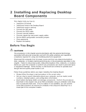
...or modems before you open the computer or perform any of the computer chassis. 23 Failure to disconnect power, telecommunications links, networks, or modems before you begin installing the Desktop Board: • Always follow the steps in each procedure in the correct order. • Set up .... • Electrostatic discharge (ESD) can continue to operate even though the front panel power button is not available, you how to: • Install the I/O shield • Install and remove the Desktop Board • Install and remove memory • Connect the IDE cable • Connect the...
...or modems before you open the computer or perform any of the computer chassis. 23 Failure to disconnect power, telecommunications links, networks, or modems before you begin installing the Desktop Board: • Always follow the steps in each procedure in the correct order. • Set up .... • Electrostatic discharge (ESD) can continue to operate even though the front panel power button is not available, you how to: • Install the I/O shield • Install and remove the Desktop Board • Install and remove memory • Connect the IDE cable • Connect the...

Product Guide
Page 24
...modules within the computer is less than the output current rating of each of the power supplies output circuits. To avoid injury, be careful of noncompliance with the chassis and associated modules. Intel Desktop Board D201GLY2 Product Guide Installation Precautions When you to refer computer servicing to Appendix B for... Hot components (like processors, voltage regulators, and heat sinks) • Damage to wires that instruct you install and test the Intel Desktop Board, observe all warnings and cautions in this section and the instructions supplied with regional laws and regulations.
...modules within the computer is less than the output current rating of each of the power supplies output circuits. To avoid injury, be careful of noncompliance with the chassis and associated modules. Intel Desktop Board D201GLY2 Product Guide Installation Precautions When you to refer computer servicing to Appendix B for... Hot components (like processors, voltage regulators, and heat sinks) • Damage to wires that instruct you install and test the Intel Desktop Board, observe all warnings and cautions in this section and the instructions supplied with regional laws and regulations.
Product Guide
Page 26
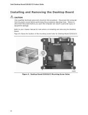
...Intel Desktop Board D201GLY2 Product Guide Installing and Removing the Desktop Board CAUTION Only qualified technical personnel should do this procedure. Refer to disconnect the power before performing the procedures described here. Figure 6 shows the location of the mounting screw holes for instructions on installing and removing the Desktop Board. Desktop Board... D201GLY2 Mounting Screw Holes 26 Disconnect the computer from its power source before you open the computer can result in ...
...Intel Desktop Board D201GLY2 Product Guide Installing and Removing the Desktop Board CAUTION Only qualified technical personnel should do this procedure. Refer to disconnect the power before performing the procedures described here. Figure 6 shows the location of the mounting screw holes for instructions on installing and removing the Desktop Board. Desktop Board... D201GLY2 Mounting Screw Holes 26 Disconnect the computer from its power source before you open the computer can result in ...
Product Guide
Page 28
... 8). 7. Insert the bottom edge of the DIMM until the retaining clips snap into the socket. 8. Replace the computer's cover and reconnect the AC power cord. 28 Installing a DIMM 4. Position the DIMM above the socket. Turn off all peripheral devices connected to the open position. 5. Holding the DIMM...place. 9. When the DIMM is inserted, push down on page 23. 2. Make sure the clips are pushed outward to the computer. Intel Desktop Board D201GLY2 Product Guide 1. Figure 8. Make sure the clips at the bottom edge of the DIMM socket are firmly in the socket (see Figure 8).
... 8). 7. Insert the bottom edge of the DIMM until the retaining clips snap into the socket. 8. Replace the computer's cover and reconnect the AC power cord. 28 Installing a DIMM 4. Position the DIMM above the socket. Turn off all peripheral devices connected to the open position. 5. Holding the DIMM...place. 9. When the DIMM is inserted, push down on page 23. 2. Make sure the clips are pushed outward to the computer. Intel Desktop Board D201GLY2 Product Guide 1. Figure 8. Make sure the clips at the bottom edge of the DIMM socket are firmly in the socket (see Figure 8).
Product Guide
Page 29
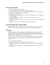
... slowest drive. NOTES ATA-100 compatible cables are attached to the same cable, the maximum transfer rate between the drives may be reduced to the Intel Desktop Board (Figure 9). 3. If an ATA-100 disk drive and a disk drive using slower IDE transfer protocols. Attach the cable end with the two closely spaced ...connectors (gray and black) to an ATAPI CD-ROM drive. Remove the AC power cord from the socket, and store it in an anti-static package. 7. Connecting the IDE Cable The IDE cable can connect two drives to reach...
... slowest drive. NOTES ATA-100 compatible cables are attached to the same cable, the maximum transfer rate between the drives may be reduced to the Intel Desktop Board (Figure 9). 3. If an ATA-100 disk drive and a disk drive using slower IDE transfer protocols. Attach the cable end with the two closely spaced ...connectors (gray and black) to an ATAPI CD-ROM drive. Remove the AC power cord from the socket, and store it in an anti-static package. 7. Connecting the IDE Cable The IDE cable can connect two drives to reach...
Product Guide
Page 33
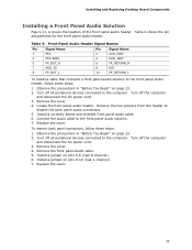
Turn off the computer and disconnect the AC power cord. 3. Locate the front panel audio header. To restore back panel operations, follow these steps: 1. Table 4. Remove the cover. 4. Observe the precautions in "...Turn off the computer and disconnect the AC power cord. 3. Remove the cover. 4. Turn off all peripheral devices connected to the computer. Install a jumper on page 23. 2. Replace the cover. 33 Turn off all peripheral devices connected to the computer. Installing and Replacing Desktop Board Components Installing a Front Panel Audio Solution Figure ...
Turn off the computer and disconnect the AC power cord. 3. Locate the front panel audio header. To restore back panel operations, follow these steps: 1. Table 4. Remove the cover. 4. Observe the precautions in "...Turn off the computer and disconnect the AC power cord. 3. Remove the cover. 4. Turn off all peripheral devices connected to the computer. Install a jumper on page 23. 2. Replace the cover. 33 Turn off all peripheral devices connected to the computer. Installing and Replacing Desktop Board Components Installing a Front Panel Audio Solution Figure ...
Product Guide
Page 34
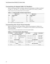
... Begin" on page 23. Front Panel Header Signal Names Pin Signal In/Out Description Pin Signal In/Out Description Hard Drive Activity LED Power LED 1 HD_PWR Out Hard disk LED pullup (330 Ω) to +5 V 2 HDR_BLNK_GRN Out Front panel green LED 3 HDA# ...Signal Name 1 Power 3 D- 5 D+ 7 Ground 9 Key Pin Signal Name 2 Power 4 D- 6 D+ 8 Ground 10 No connect Note: USB ports may be assigned as needed. Table 6 shows the pin assignments for the headers. Table 5. Table 6. Table 5 shows the pin assignments for the front panel header. Intel Desktop Board D201GLY2 Product ...
... Begin" on page 23. Front Panel Header Signal Names Pin Signal In/Out Description Pin Signal In/Out Description Hard Drive Activity LED Power LED 1 HD_PWR Out Hard disk LED pullup (330 Ω) to +5 V 2 HDR_BLNK_GRN Out Front panel green LED 3 HDA# ...Signal Name 1 Power 3 D- 5 D+ 7 Ground 9 Key Pin Signal Name 2 Power 4 D- 6 D+ 8 Ground 10 No connect Note: USB ports may be assigned as needed. Table 6 shows the pin assignments for the headers. Table 5. Table 6. Table 5 shows the pin assignments for the front panel header. Intel Desktop Board D201GLY2 Product ...
Product Guide
Page 36
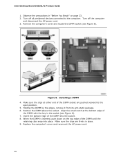
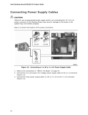
... or 2 x 12 Power Supply Cable 1. Connect the main power supply cable (2 x10 or 2 x 12) to the 2 x 2 connector (Figure 13). 3. Figure 13 shows the location of the power connectors. Intel Desktop Board D201GLY2 Product Guide Connecting Power Supply Cables CAUTION Failure to use an appropriate power supply and/or not connecting the 12 V (2 x 2) power connector to the Desktop Board may not function...
... or 2 x 12 Power Supply Cable 1. Connect the main power supply cable (2 x10 or 2 x 12) to the 2 x 2 connector (Figure 13). 3. Figure 13 shows the location of the power connectors. Intel Desktop Board D201GLY2 Product Guide Connecting Power Supply Cables CAUTION Failure to use an appropriate power supply and/or not connecting the 12 V (2 x 2) power connector to the Desktop Board may not function...

