Product Guide
Page 2
... a Class B digital device, pursuant to Part 15 of documents which may contain design defects or errors known as provided in this device must accept any time, without notice. For questions related to sale and/or use . Desktop Board D201GLY may cause the product to obtain the latest specifications and before placing your distributor to deviate from Intel Corporation by going...
... a Class B digital device, pursuant to Part 15 of documents which may contain design defects or errors known as provided in this device must accept any time, without notice. For questions related to sale and/or use . Desktop Board D201GLY may cause the product to obtain the latest specifications and before placing your distributor to deviate from Intel Corporation by going...
Product Guide
Page 5
... Main Memory ...13 Chipset ...14 Graphics Subsystem 14 Audio Subsystem 14 Input/Output (I/O) Controller 15 LAN Subsystem 15 LAN Subsystem Software 16 RJ-45 LAN Connector LEDs 16 Hi-Speed USB 2.0 Support 17 Enhanced IDE Interface 17 Expandability...17 BIOS ...17 IDE Auto Configuration 17 PCI Auto Configuration 18 Security Passwords 18 Power Management Features 18 ACPI ...18 Hardware Support 19 Power Connectors 19 Fan Headers 19 LAN Wake Capabilities 20 Wake from USB 20 Wake from PS/2 Keyboard/Mouse 20 PME# Wakeup Support 20 Battery ...20 Real-Time Clock...
... Main Memory ...13 Chipset ...14 Graphics Subsystem 14 Audio Subsystem 14 Input/Output (I/O) Controller 15 LAN Subsystem 15 LAN Subsystem Software 16 RJ-45 LAN Connector LEDs 16 Hi-Speed USB 2.0 Support 17 Enhanced IDE Interface 17 Expandability...17 BIOS ...17 IDE Auto Configuration 17 PCI Auto Configuration 18 Security Passwords 18 Power Management Features 18 ACPI ...18 Hardware Support 19 Power Connectors 19 Fan Headers 19 LAN Wake Capabilities 20 Wake from USB 20 Wake from PS/2 Keyboard/Mouse 20 PME# Wakeup Support 20 Battery ...20 Real-Time Clock...
Product Guide
Page 6
Intel Desktop Board D201GLY Product Guide Setting the Desktop Board Jumpers 34 Front Panel Audio Header/Jumper Block 34 BIOS Configuration Jumper 35 Clearing Passwords 36 Replacing the Battery 37 3 Updating the BIOS Updating the BIOS with the Iflash Memory Update Utility 43 Obtaining the BIOS Update File 43 Updating the BIOS with the Iflash Memory Update Utility 43 Recovering the BIOS 44 A BIOS Error Messages BIOS Front-panel Power LED Codes 45 BIOS Error Messages 45 B Regulatory Compliance Safety Regulations 47 Place Battery Marking 47 European Union Declaration of Conformity ...
Intel Desktop Board D201GLY Product Guide Setting the Desktop Board Jumpers 34 Front Panel Audio Header/Jumper Block 34 BIOS Configuration Jumper 35 Clearing Passwords 36 Replacing the Battery 37 3 Updating the BIOS Updating the BIOS with the Iflash Memory Update Utility 43 Obtaining the BIOS Update File 43 Updating the BIOS with the Iflash Memory Update Utility 43 Recovering the BIOS 44 A BIOS Error Messages BIOS Front-panel Power LED Codes 45 BIOS Error Messages 45 B Regulatory Compliance Safety Regulations 47 Place Battery Marking 47 European Union Declaration of Conformity ...
Product Guide
Page 7
... Ethernet LAN Connector LEDs 16 4. Hi-Speed USB 2.0 Header Signal Names 31 6. BIOS Error Messages 45 11. Lead-Free Board Markings 52 13. Front Panel Audio Header Signal Names 30 5. Product Certification Markings 55 vii Internal Headers 29 11. Feature Summary 9 2. Front Panel Header Signal Names 31 7. Installing a DIMM 26 9. Front Panel Audio Header/Jumper Block 35 8. Location of the Standby Power Indicator 19 5. Intel Desktop Board D201GLY Components 11 2. Safety Regulations 47 12. Jumper Settings for the BIOS Setup Program Modes 35 9. Connecting...
... Ethernet LAN Connector LEDs 16 4. Hi-Speed USB 2.0 Header Signal Names 31 6. BIOS Error Messages 45 11. Lead-Free Board Markings 52 13. Front Panel Audio Header Signal Names 30 5. Product Certification Markings 55 vii Internal Headers 29 11. Feature Summary 9 2. Front Panel Header Signal Names 31 7. Installing a DIMM 26 9. Front Panel Audio Header/Jumper Block 35 8. Location of the Standby Power Indicator 19 5. Intel Desktop Board D201GLY Components 11 2. Safety Regulations 47 12. Jumper Settings for the BIOS Setup Program Modes 35 9. Connecting...
Product Guide
Page 9
... ATA-100 support (two devices) • One VGA connector • One parallel port • One serial port • PS/2* keyboard and mouse ports • Intel® BIOS • Support for SMBIOS • Intel® Rapid BIOS Boot LAN Support • 10/100 Mb/s LAN Subsystem Power Management • Support for S3 • Wake on USB, PCI, PS/2, LAN, and front panel 9 1 Desktop Board Features This chapter briefly describes the main features of the Desktop Board. no support for Advanced Configuration and Power Interface (ACPI);
... ATA-100 support (two devices) • One VGA connector • One parallel port • One serial port • PS/2* keyboard and mouse ports • Intel® BIOS • Support for SMBIOS • Intel® Rapid BIOS Boot LAN Support • 10/100 Mb/s LAN Subsystem Power Management • Support for S3 • Wake on USB, PCI, PS/2, LAN, and front panel 9 1 Desktop Board Features This chapter briefly describes the main features of the Desktop Board. no support for Advanced Configuration and Power Interface (ACPI);
Product Guide
Page 12
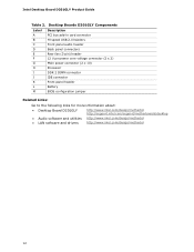
... M Description PCI bus add-in card connector Hi-speed USB 2.0 headers Front panel audio header Back panel connectors Rear fan (3-pin) header 12 V processor core voltage connector (2 x 2) Main power connector (2 x 10) Processor DDR 2 DIMM connector IDE connector Front panel header Battery BIOS configuration jumper Related Links: Go to the following links for more information about: • Desktop Board D201GLY • Audio software and utilities • LAN software and drivers http://www.intel.com/design/motherbd http://support.intel.com/support/motherboards/desktop http://www.intel.com...
... M Description PCI bus add-in card connector Hi-speed USB 2.0 headers Front panel audio header Back panel connectors Rear fan (3-pin) header 12 V processor core voltage connector (2 x 2) Main power connector (2 x 10) Processor DDR 2 DIMM connector IDE connector Front panel header Battery BIOS configuration jumper Related Links: Go to the following links for more information about: • Desktop Board D201GLY • Audio software and utilities • LAN software and drivers http://www.intel.com/design/motherbd http://support.intel.com/support/motherboards/desktop http://www.intel.com...
Product Guide
Page 13
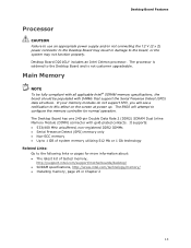
... latest list of tested memory, http://support.intel.com/support/motherboards/desktop/ • SDRAM specifications, http://www.intel.com/technology/memory/ • Installing memory, page 25 in damage to the board, or the system may not function properly. The Desktop Board has one 240-pin Double Data Rate 2 (DDR2) SDRAM Dual Inline Memory Module (DIMM) connector with DIMMs that support the Serial Presence Detect (SPD) data structure. Desktop Board D201GLY includes an Intel Celeron processor. The processor is...
... latest list of tested memory, http://support.intel.com/support/motherboards/desktop/ • SDRAM specifications, http://www.intel.com/technology/memory/ • Installing memory, page 25 in damage to the board, or the system may not function properly. The Desktop Board has one 240-pin Double Data Rate 2 (DDR2) SDRAM Dual Inline Memory Module (DIMM) connector with DIMMs that support the Serial Presence Detect (SPD) data structure. Desktop Board D201GLY includes an Intel Celeron processor. The processor is...
Product Guide
Page 14
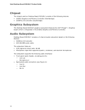
Intel Desktop Board D201GLY Product Guide Chipset The chipset used on the following audio interfaces: • Front panel audio header, including pins for: ― Line out ― Microphone in the SiS662 Graphics and Memory Controller. Audio Subsystem Desktop Board D201GLY includes a 2-channel audio subsystem based on Desktop Board D201GLY consists of the following devices: • SiS662 Graphics and Memory Controller (Northbridge) • SiS964L I /O Controller • ADI AD1888 audio codec The subsystem features: • S/N (signal-to-noise) ratio: 90 dB • Microphone input...
Intel Desktop Board D201GLY Product Guide Chipset The chipset used on the following audio interfaces: • Front panel audio header, including pins for: ― Line out ― Microphone in the SiS662 Graphics and Memory Controller. Audio Subsystem Desktop Board D201GLY includes a 2-channel audio subsystem based on Desktop Board D201GLY consists of the following devices: • SiS662 Graphics and Memory Controller (Northbridge) • SiS964L I /O Controller • ADI AD1888 audio codec The subsystem features: • S/N (signal-to-noise) ratio: 90 dB • Microphone input...
Product Guide
Page 15
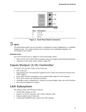
... utilities http://support.intel.com/support/motherboards/desktop/ • Installing a front panel audio solution (page 30) Input/Output (I/O) Controller The super I/O controller features the following: • One serial port • One parallel port with Extended Capabilities Port (ECP) and Enhanced Parallel Port (EPP) support • Serial IRQ interface compatible with serialized IRQ support for PCI systems • PS/2-style mouse and keyboard interfaces • Intelligent power management, including a programmable wake up event interface • PCI power management support LAN...
... utilities http://support.intel.com/support/motherboards/desktop/ • Installing a front panel audio solution (page 30) Input/Output (I/O) Controller The super I/O controller features the following: • One serial port • One parallel port with Extended Capabilities Port (ECP) and Enhanced Parallel Port (EPP) support • Serial IRQ interface compatible with serialized IRQ support for PCI systems • PS/2-style mouse and keyboard interfaces • Intelligent power management, including a programmable wake up event interface • PCI power management support LAN...
Product Guide
Page 17
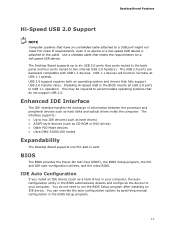
...-ROM or DVD drives) • Older PIO Mode devices • Ultra DMA-33/66/100 modes Expandability The Desktop Board supports one PCI add-in the BIOS automatically detects and configures the device for a full-speed USB device. This may be required to two internal USB 2.0 headers). IDE Auto Configuration If you install an IDE device (such as hard disks and optical drives inside the computer. You can override the auto-configuration options by specifying manual configuration in the BIOS reverts all USB 2.0 ports to the cable...
...-ROM or DVD drives) • Older PIO Mode devices • Ultra DMA-33/66/100 modes Expandability The Desktop Board supports one PCI add-in the BIOS automatically detects and configures the device for a full-speed USB device. This may be required to two internal USB 2.0 headers). IDE Auto Configuration If you install an IDE device (such as hard disks and optical drives inside the computer. You can override the auto-configuration options by specifying manual configuration in the BIOS reverts all USB 2.0 ports to the cable...
Product Guide
Page 18
...BIOS Setup program after you install a PCI add-in card. A supervisor password and a user password can enter either the supervisor password or the user password to view and change all Setup options. Setup options are set , the computer boots without asking for a password. The password prompt is displayed before the computer is implemented at the password prompt of ACPI with the following restrictions: • The supervisor password gives unrestricted access to access Setup. Intel Desktop Board D201GLY Product Guide PCI Auto Configuration If you install a PCI add-in card...
...BIOS Setup program after you install a PCI add-in card. A supervisor password and a user password can enter either the supervisor password or the user password to view and change all Setup options. Setup options are set , the computer boots without asking for a password. The password prompt is displayed before the computer is implemented at the password prompt of ACPI with the following restrictions: • The supervisor password gives unrestricted access to access Setup. Intel Desktop Board D201GLY Product Guide PCI Auto Configuration If you install a PCI add-in card...
Product Guide
Page 19
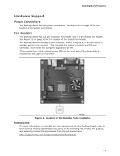
... system has a dual-colored power LED on standby current requirements for the Desktop Board, refer to the Technical Product Specification by the LED turning amber. Figure 4. See Figure 12 on page 32 for the location of the chassis fan header. See Figure 11 on page 33 for the location of the power connectors. Desktop Board Features Hardware Support Power Connectors The Desktop Board has two power connectors. This includes the memory module and PCI bus connector, even when...
... system has a dual-colored power LED on standby current requirements for the Desktop Board, refer to the Technical Product Specification by the LED turning amber. Figure 4. See Figure 12 on page 32 for the location of the chassis fan header. See Figure 11 on page 33 for the location of the power connectors. Desktop Board Features Hardware Support Power Connectors The Desktop Board has two power connectors. This includes the memory module and PCI bus connector, even when...
Product Guide
Page 20
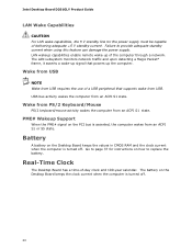
... an ACPI S1 state. PME# Wakeup Support When the PME# signal on the PCI bus is asserted, the computer wakes from USB requires the use of a USB peripheral that powers up of the computer through a network. Real-Time Clock The Desktop Board has a time-of delivering adequate +5 V standby current. Intel Desktop Board D201GLY Product Guide LAN Wake Capabilities CAUTION For LAN wake capabilities, the 5 V standby line for instructions on how to replace the battery. Failure to...
... an ACPI S1 state. PME# Wakeup Support When the PME# signal on the PCI bus is asserted, the computer wakes from USB requires the use of a USB peripheral that powers up of the computer through a network. Real-Time Clock The Desktop Board has a time-of delivering adequate +5 V standby current. Intel Desktop Board D201GLY Product Guide LAN Wake Capabilities CAUTION For LAN wake capabilities, the 5 V standby line for instructions on how to replace the battery. Failure to...
Product Guide
Page 21
... or perform any of the computer chassis. 21 Some circuitry on the board can continue to operate even though the front panel power button is not available, you how to: • Install the I/O shield • Install and remove the Desktop Board • Install and remove memory • Connect the IDE cable • Connect internal headers • Connect chassis fan and power supply cables • Set the BIOS configuration and audio jumpers • Clear passwords • Replace the battery Before You Begin CAUTIONS The procedures...
... or perform any of the computer chassis. 21 Some circuitry on the board can continue to operate even though the front panel power button is not available, you how to: • Install the I/O shield • Install and remove the Desktop Board • Install and remove memory • Connect the IDE cable • Connect internal headers • Connect chassis fan and power supply cables • Set the BIOS configuration and audio jumpers • Clear passwords • Replace the battery Before You Begin CAUTIONS The procedures...
Product Guide
Page 30
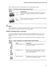
... front panel audio solution. 7. Replace the cover. Turn off all peripheral devices connected to the computer. Install a jumper on pins 9-10 (rear L channel). 7. Turn off the computer and disconnect the AC power cord. 3. Install a correctly keyed and shielded front panel audio cable. 6. Observe the precautions in "Before You Begin" on page 21. 2. Table 4 shows the pin assignments for the front panel audio header. Locate the front panel audio header. Replace the cover. 30 Intel Desktop Board D201GLY Product Guide Installing a Front Panel Audio Solution...
... front panel audio solution. 7. Replace the cover. Turn off all peripheral devices connected to the computer. Install a jumper on pins 9-10 (rear L channel). 7. Turn off the computer and disconnect the AC power cord. 3. Install a correctly keyed and shielded front panel audio cable. 6. Observe the precautions in "Before You Begin" on page 21. 2. Table 4 shows the pin assignments for the front panel audio header. Locate the front panel audio header. Replace the cover. 30 Intel Desktop Board D201GLY Product Guide Installing a Front Panel Audio Solution...
Product Guide
Page 35
... Setup program modes. Configure (2-3) After the Power-On Self-Test (POST) runs, the BIOS displays the Maintenance Menu. Use this header is used for front panel audio, the back panel audio line out and mic-in signals are routed to the back panel connectors. No jumpers installed Table 4 lists the names of the signals available on this header/jumper block. BIOS Configuration Jumper The three-pin BIOS jumper block enables all board configuration to clear passwords. Figure 13, B shows the location of the Desktop Board's BIOS configuration jumper block. Recovery...
... Setup program modes. Configure (2-3) After the Power-On Self-Test (POST) runs, the BIOS displays the Maintenance Menu. Use this header is used for front panel audio, the back panel audio line out and mic-in signals are routed to the back panel connectors. No jumpers installed Table 4 lists the names of the signals available on this header/jumper block. BIOS Configuration Jumper The three-pin BIOS jumper block enables all board configuration to clear passwords. Figure 13, B shows the location of the Desktop Board's BIOS configuration jumper block. Recovery...
Product Guide
Page 36
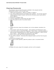
... computer cover. 12. Use the arrow keys to normal mode. 1. To restore normal operation, place the jumper on the computer. 36 Intel Desktop Board D201GLY Product Guide Clearing Passwords This procedure assumes that you confirm clearing the password. Turn off the computer. Remove the computer cover. 4. Replace the cover, plug in the computer and the configuration jumper is set to select Clear Passwords. The computer starts the Setup program. Find the configuration jumper block (see Figure...
... computer cover. 12. Use the arrow keys to normal mode. 1. To restore normal operation, place the jumper on the computer. 36 Intel Desktop Board D201GLY Product Guide Clearing Passwords This procedure assumes that you confirm clearing the password. Turn off the computer. Remove the computer cover. 4. Replace the cover, plug in the computer and the configuration jumper is set to select Clear Passwords. The computer starts the Setup program. Find the configuration jumper block (see Figure...
Product Guide
Page 43
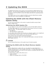
... pressing the key after the Power-On Self-Test (POST) memory test begins and before the operating system boot begins. You can obtain either of the BIOS by using the Iflash BIOS update file. The Iflash BIOS update file contains: • New BIOS file • Intel Flash Memory Update Utility You can access the BIOS Setup program by navigating to the Desktop Board D201GLY page on the Intel World Wide Web site at: http://support.intel.com/support/motherboards/desktop Navigate to...
... pressing the key after the Power-On Self-Test (POST) memory test begins and before the operating system boot begins. You can obtain either of the BIOS by using the Iflash BIOS update file. The Iflash BIOS update file contains: • New BIOS file • Intel Flash Memory Update Utility You can access the BIOS Setup program by navigating to the Desktop Board D201GLY page on the Intel World Wide Web site at: http://support.intel.com/support/motherboards/desktop Navigate to...
Product Guide
Page 44
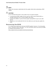
... recovering the BIOS for desktop board D201GLY, go to a bootable USB flash drive or other bootable USB media. 2. Manually run the IFLASH.EXE file from the USB device and manually update the BIOS. Uncompress the BIOS update file and copy the .BIO file and IFLASH.EXE to : http://support.intel.com/support/motherboards/desktop/ 44 Configure the BIOS or use the F10 key option during POST to boot to the USB device. 3. Intel Desktop Board D201GLY Product Guide NOTE Review the instructions distributed with the update utility before attempting a BIOS update. Recovering the BIOS It is...
... recovering the BIOS for desktop board D201GLY, go to a bootable USB flash drive or other bootable USB media. 2. Manually run the IFLASH.EXE file from the USB device and manually update the BIOS. Uncompress the BIOS update file and copy the .BIO file and IFLASH.EXE to : http://support.intel.com/support/motherboards/desktop/ 44 Configure the BIOS or use the F10 key option during POST to boot to the USB device. 3. Intel Desktop Board D201GLY Product Guide NOTE Review the instructions distributed with the update utility before attempting a BIOS update. Recovering the BIOS It is...
Product Guide
Page 45
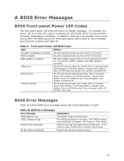
...) until BIOS update is incorrect. The CMOS memory may be bad. For example, the power LED is on when the system is complete. Run Setup to blink an error message describing the problem (see Table 9). In addition, whenever a recoverable error occurs during POST, the BIOS causes the front-panel power LED to reset values. The CMOS checksum is complete. Front-panel Power LED Blink Codes Type Processor initialization complete POST complete BIOS update in progress Video error Pattern...
...) until BIOS update is incorrect. The CMOS memory may be bad. For example, the power LED is on when the system is complete. Run Setup to blink an error message describing the problem (see Table 9). In addition, whenever a recoverable error occurs during POST, the BIOS causes the front-panel power LED to reset values. The CMOS checksum is complete. Front-panel Power LED Blink Codes Type Processor initialization complete POST complete BIOS update in progress Video error Pattern...


