Product Guide
Page 3
... for Intended Applications All Intel Desktop Boards are evaluated as Information Technology Equipment (I.T.E.) for use in personal computers (PC) for installation in this manual: CAUTION Cautions warn the user about how to prevent damage to update the BIOS 4 Configuring for RAID (Intel® Matrix Storage Technology (Intel® MST)): information about configuring your system for general audiences. Preface This Product Guide gives information about board layout, component installation, BIOS update, and regulatory requirements...
... for Intended Applications All Intel Desktop Boards are evaluated as Information Technology Equipment (I.T.E.) for use in personal computers (PC) for installation in this manual: CAUTION Cautions warn the user about how to prevent damage to update the BIOS 4 Configuring for RAID (Intel® Matrix Storage Technology (Intel® MST)): information about configuring your system for general audiences. Preface This Product Guide gives information about board layout, component installation, BIOS update, and regulatory requirements...
Product Guide
Page 5
... Intel G45 Graphics Subsystem 15 DVI-I Support 15 HDMI* Technology Support 15 Intel® Viiv™ Technology 15 Audio Subsystem 16 Legacy Input/Output (I/O) Controller 17 LAN Subsystem 17 LAN Subsystem Software 17 LAN Status Indicators 17 Hi-Speed USB 2.0 Support 18 Serial ATA...19 Serial ATA RAID 19 Intel® Rapid Recover Technology (Intel® RRT 19 Expandability...19 BIOS ...20 Serial ATA Auto Configuration 20 PCI Express* Auto Configuration 20 Security Passwords 20 Hardware Management Features 21 Fan Speed, Thermal, and Voltage Monitoring and Control 21 Chassis...
... Intel G45 Graphics Subsystem 15 DVI-I Support 15 HDMI* Technology Support 15 Intel® Viiv™ Technology 15 Audio Subsystem 16 Legacy Input/Output (I/O) Controller 17 LAN Subsystem 17 LAN Subsystem Software 17 LAN Status Indicators 17 Hi-Speed USB 2.0 Support 18 Serial ATA...19 Serial ATA RAID 19 Intel® Rapid Recover Technology (Intel® RRT 19 Expandability...19 BIOS ...20 Serial ATA Auto Configuration 20 PCI Express* Auto Configuration 20 Security Passwords 20 Hardware Management Features 21 Fan Speed, Thermal, and Voltage Monitoring and Control 21 Chassis...
Product Guide
Page 6
... (SATA) Cables 40 Connecting to Internal Headers and Connectors 41 Front Panel HD Audio Header 42 Chassis Intrusion Header 42 Consumer IR (CIR) Headers 42 USB 2.0 Headers 43 Serial Port Header 44 Alternate Front Panel Power LED Header 44 Front Panel Header 44 Connecting to the Audio System 45 Connecting Chassis Fan and Power Supply Cables 46 Chassis Fan Cables 46 Power Supply Cables 47 Setting the BIOS Configuration Jumper 48 Clearing Passwords 49 Replacing the Battery 50 3 Updating the BIOS 55 Updating the BIOS with the Intel® Express BIOS Update Utility 55 Updating the...
... (SATA) Cables 40 Connecting to Internal Headers and Connectors 41 Front Panel HD Audio Header 42 Chassis Intrusion Header 42 Consumer IR (CIR) Headers 42 USB 2.0 Headers 43 Serial Port Header 44 Alternate Front Panel Power LED Header 44 Front Panel Header 44 Connecting to the Audio System 45 Connecting Chassis Fan and Power Supply Cables 46 Chassis Fan Cables 46 Power Supply Cables 47 Setting the BIOS Configuration Jumper 48 Clearing Passwords 49 Replacing the Battery 50 3 Updating the BIOS 55 Updating the BIOS with the Intel® Express BIOS Update Utility 55 Updating the...
Product Guide
Page 7
... BIOS Configuration Jumper Block 48 22. Lift the Load Plate 32 8. Connecting the Processor Fan Heat Sink Cable 35 13. Desktop Board DG45FC China RoHS Material Self Declaration Table 75 Tables 1. Audio Jack Retasking Support 16 4. Remove the Protective Socket Cover 32 9. Remove the Processor from the Protective Processor Cover 33 10. Dual Channel Memory Configuration Example 36 14. Internal Headers and Connectors 41 18. Desktop Board DG45FC Components 12 3. LAN Status LEDs 18 3. Install the Processor 33 11. Connecting a Serial ATA Cable...
... BIOS Configuration Jumper Block 48 22. Lift the Load Plate 32 8. Connecting the Processor Fan Heat Sink Cable 35 13. Desktop Board DG45FC China RoHS Material Self Declaration Table 75 Tables 1. Audio Jack Retasking Support 16 4. Remove the Protective Socket Cover 32 9. Remove the Processor from the Protective Processor Cover 33 10. Dual Channel Memory Configuration Example 36 14. Internal Headers and Connectors 41 18. Desktop Board DG45FC Components 12 3. LAN Status LEDs 18 3. Install the Processor 33 11. Connecting a Serial ATA Cable...
Product Guide
Page 9
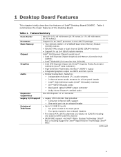
... audio Expansion Capabilities Legacy I/O Support Peripheral Interfaces One PCI Express 1.1 x1 connector • Legacy I/O Controller that provides: ― Consumer Infrared (CIR) support ― One serial port via an onboard header • Up to 10 USB 2.0 ports ― Six ports routed to the back panel ― Four ports routed to two onboard headers • Five Serial ATA (SATA) channels (3.0 Gb/s) via ICH10R including one external SATA (eSATA) channel • SATA RAID support via Intel® Matrix Storage Technology (Intel® MST) including support for Intel...
... audio Expansion Capabilities Legacy I/O Support Peripheral Interfaces One PCI Express 1.1 x1 connector • Legacy I/O Controller that provides: ― Consumer Infrared (CIR) support ― One serial port via an onboard header • Up to 10 USB 2.0 ports ― Six ports routed to the back panel ― Four ports routed to two onboard headers • Five Serial ATA (SATA) channels (3.0 Gb/s) via ICH10R including one external SATA (eSATA) channel • SATA RAID support via Intel® Matrix Storage Technology (Intel® MST) including support for Intel...
Product Guide
Page 10
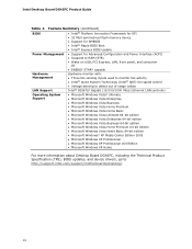
... Mbit symmetrical flash memory device • Support for SMBIOS • Intel® Rapid BIOS Boot • Intel® Express BIOS Update Power Management • Support for Advanced Configuration and Power Interface (ACPI) • Suspend to RAM (STR) • Wake on USB, PCI Express, LAN, front panel, and consumer IR • ENERGY STAR* capable Hardware Management Hardware monitor with: • Three fan sensing inputs used to monitor fan activity • Intel® Quiet System Technology (Intel® QST) fan speed control LAN Support • Voltage sensing to detect...
... Mbit symmetrical flash memory device • Support for SMBIOS • Intel® Rapid BIOS Boot • Intel® Express BIOS Update Power Management • Support for Advanced Configuration and Power Interface (ACPI) • Suspend to RAM (STR) • Wake on USB, PCI Express, LAN, front panel, and consumer IR • ENERGY STAR* capable Hardware Management Hardware monitor with: • Three fan sensing inputs used to monitor fan activity • Intel® Quiet System Technology (Intel® QST) fan speed control LAN Support • Voltage sensing to detect...
Product Guide
Page 19
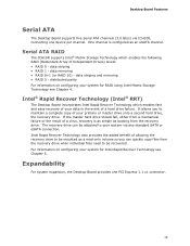
... Desktop Board incorporates Intel Rapid Recover Technology which enables the following RAID (Redundant Array of a hard drive failure. Expandability For system expansion, the Desktop Board provides one device per channel. One channel is as simple as booting from the recovery drive when individual files need to be mounted as an eSATA channel. data striping • RAID 1 - data striping and mirroring • RAID 5 - For information on configuring your system via ICH10R, connecting one PCI Express 1.1 x1 connector...
... Desktop Board incorporates Intel Rapid Recover Technology which enables the following RAID (Redundant Array of a hard drive failure. Expandability For system expansion, the Desktop Board provides one device per channel. One channel is as simple as booting from the recovery drive when individual files need to be mounted as an eSATA channel. data striping • RAID 1 - data striping and mirroring • RAID 5 - For information on configuring your system via ICH10R, connecting one PCI Express 1.1 x1 connector...
Product Guide
Page 20
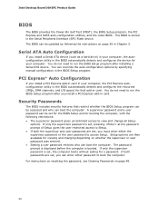
... the supervisor password is set , you install a PCI Express add-in card in the BIOS automatically detects and configures the device for a password. Intel Desktop Board DG45FC Product Guide BIOS The BIOS provides the Power-On Self-Test (POST), the BIOS Setup program, the PCI Express and SATA auto-configuration utilities, and the video BIOS. PCI Express* Auto Configuration If you must enter either password to run the BIOS Setup program after you install a PCI Express add-in the BIOS Setup program. For instructions on resetting the password, see Clearing Passwords on page...
... the supervisor password is set , you install a PCI Express add-in card in the BIOS automatically detects and configures the device for a password. Intel Desktop Board DG45FC Product Guide BIOS The BIOS provides the Power-On Self-Test (POST), the BIOS Setup program, the PCI Express and SATA auto-configuration utilities, and the video BIOS. PCI Express* Auto Configuration If you must enter either password to run the BIOS Setup program after you install a PCI Express add-in the BIOS Setup program. For instructions on resetting the password, see Clearing Passwords on page...

Product Guide
Page 21
... removed. Chassis Intrusion The board supports a chassis security feature that can adjust fan speed according to the chassis intrusion header on the chassis that can be connected to thermal conditions. • Fan speed controllers and sensors integrated into the ICH10R • Thermal sensors in the Channel A socket to enable Intel Quiet System Technology. • Thermally monitored closed-loop fan control, for the GMCH is 66 °C. See Figure 17 for Management (WfM) specification. Desktop Board...
... removed. Chassis Intrusion The board supports a chassis security feature that can adjust fan speed according to the chassis intrusion header on the chassis that can be connected to thermal conditions. • Fan speed controllers and sensors integrated into the ICH10R • Thermal sensors in the Channel A socket to enable Intel Quiet System Technology. • Thermally monitored closed-loop fan control, for the GMCH is 66 °C. See Figure 17 for Management (WfM) specification. Desktop Board...
Product Guide
Page 22
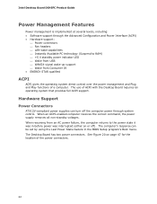
... Plug and Play functions of a computer. Hardware Support Power Connectors ATX12V-compliant power supplies can be set by using the Last Power State feature in before power was in the BIOS Setup program's Boot menu. When an ACPI-enabled computer receives the correct command, the power supply removes all non-standby voltages. See Figure 20 on or off the computer power through the Advanced Configuration and Power Interface (ACPI) • Hardware support: ⎯ Power connectors ⎯ Fan headers ⎯ LAN wake...
... Plug and Play functions of a computer. Hardware Support Power Connectors ATX12V-compliant power supplies can be set by using the Last Power State feature in before power was in the BIOS Setup program's Boot menu. When an ACPI-enabled computer receives the correct command, the power supply removes all non-standby voltages. See Figure 20 on or off the computer power through the Advanced Configuration and Power Interface (ACPI) • Hardware support: ⎯ Power connectors ⎯ Fan headers ⎯ LAN wake...
Product Guide
Page 23
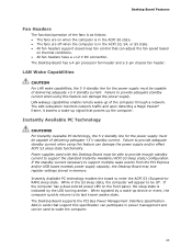
Instantly Available PC technology enables the board to provide adequate standby current when using this feature can damage the power supply. LAN wakeup capabilities enable remote wake-up signal that support this Desktop Board must be used with this specification can participate in power management and can adjust the fan speed based on thermal conditions. • All fan headers have a +12 V DC connection. Failure to enter the ACPI S3 (Suspend-toRAM) sleep state. While in...
Instantly Available PC technology enables the board to provide adequate standby current when using this feature can damage the power supply. LAN wakeup capabilities enable remote wake-up signal that support this Desktop Board must be used with this specification can participate in power management and can adjust the fan speed based on thermal conditions. • All fan headers have a +12 V DC connection. Failure to enter the ACPI S3 (Suspend-toRAM) sleep state. While in...
Product Guide
Page 27
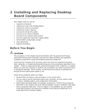
... panel power button is not available, you open the computer or perform any of the computer chassis. 27 2 Installing and Replacing Desktop Board Components This chapter tells you how to: • Install the I/O shield • Install and remove the Desktop Board • Install and remove a processor • Install and remove memory • Connect the Serial ATA cables • Connect to the internal headers • Connect to the onboard audio system • Connect chassis fan and power supply cables • Set the BIOS configuration jumper • Clear passwords • Replace...
... panel power button is not available, you open the computer or perform any of the computer chassis. 27 2 Installing and Replacing Desktop Board Components This chapter tells you how to: • Install the I/O shield • Install and remove the Desktop Board • Install and remove a processor • Install and remove memory • Connect the Serial ATA cables • Connect to the internal headers • Connect to the onboard audio system • Connect chassis fan and power supply cables • Set the BIOS configuration jumper • Clear passwords • Replace...
Product Guide
Page 35
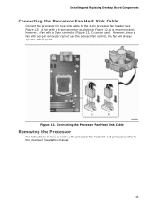
... fan with a 3-pin connector (Figure 12, B) can be used. Connecting the Processor Fan Heat Sink Cable Removing the Processor For instructions on how to remove the processor fan heat sink and processor, refer to the 4-pin processor fan header (see Figure 12). however, a fan with a 3-pin connector cannot use the onboard fan control, the fan will always operate at full speed. Figure 12. Installing and Replacing Desktop Board Components Connecting the Processor Fan Heat Sink Cable Connect the processor fan heat sink cable to the processor installation manual. 35 A fan with a 4-pin connector...
... fan with a 3-pin connector (Figure 12, B) can be used. Connecting the Processor Fan Heat Sink Cable Removing the Processor For instructions on how to remove the processor fan heat sink and processor, refer to the 4-pin processor fan header (see Figure 12). however, a fan with a 3-pin connector cannot use the onboard fan control, the fan will always operate at full speed. Figure 12. Installing and Replacing Desktop Board Components Connecting the Processor Fan Heat Sink Cable Connect the processor fan heat sink cable to the processor installation manual. 35 A fan with a 4-pin connector...

Product Guide
Page 43
..., even if no device or a low-speed USB device is attached to Enabled. Installing and Replacing Desktop Board Components NOTE The Consumer IR option must be used to connect two USB devices. Table 7. Back Panel CIR Emitter (Output) Header Signal Names Pin Signal Name 1 Emitter Out 1 3 Ground 5 Jack Detect 1 Pin Signal Name 2 Emitter Out 2 4 Key (no pin) Pin Signal Name 2 LED 4 Learn-In 6 Vcc 8 CIR Input Table 8. USB Port B Signal Name Power (+5 V) DD+ Ground No...
..., even if no device or a low-speed USB device is attached to Enabled. Installing and Replacing Desktop Board Components NOTE The Consumer IR option must be used to connect two USB devices. Table 7. Back Panel CIR Emitter (Output) Header Signal Names Pin Signal Name 1 Emitter Out 1 3 Ground 5 Jack Detect 1 Pin Signal Name 2 Emitter Out 2 4 Key (no pin) Pin Signal Name 2 LED 4 Learn-In 6 Vcc 8 CIR Input Table 8. USB Port B Signal Name Power (+5 V) DD+ Ground No...
Product Guide
Page 49
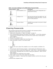
... Jumper Settings for the BIOS Setup Program Modes Jumper Setting Mode Normal (default) (1-2) Description The BIOS uses the current configuration and passwords for booting. The computer starts the Setup program. Select Yes and press . Configure (2-3) Recovery (None) After the Power-On Self-Test (POST) runs, the BIOS displays the Maintenance Menu. Installing and Replacing Desktop Board Components Table 13. Use this menu to the computer. Observe the precautions in the computer, turn on page 27. 2. Turn off all peripheral devices connected to clear passwords...
... Jumper Settings for the BIOS Setup Program Modes Jumper Setting Mode Normal (default) (1-2) Description The BIOS uses the current configuration and passwords for booting. The computer starts the Setup program. Select Yes and press . Configure (2-3) Recovery (None) After the Power-On Self-Test (POST) runs, the BIOS displays the Maintenance Menu. Installing and Replacing Desktop Board Components Table 13. Use this menu to the computer. Observe the precautions in the computer, turn on page 27. 2. Turn off all peripheral devices connected to clear passwords...
Product Guide
Page 55
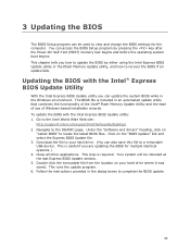
... this file to a removable USB device. Download the file to view and change the BIOS settings for multiple identical systems.) 4. Double-click the executable file from the location on the "BIOS Update" link and select the Express BIOS Update file. 3. The BIOS file is required. Your system will be used to your hard drive where it was saved. This runs the update program. 6. You can access the BIOS Setup program by either using the Intel Express BIOS Update utility or the Iflash Memory Update utility...
... this file to a removable USB device. Download the file to view and change the BIOS settings for multiple identical systems.) 4. Double-click the executable file from the location on the "BIOS Update" link and select the Express BIOS Update file. 3. The BIOS file is required. Your system will be used to your hard drive where it was saved. This runs the update program. 6. You can access the BIOS Setup program by either using the Intel Express BIOS Update utility or the Iflash Memory Update utility...
Product Guide
Page 58
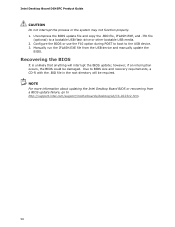
... use the F10 option during POST to boot to a bootable USB flash drive or other bootable USB media. 2. Due to http://support.intel.com/support/motherboards/desktop/sb/CS-022312.htm. 58 Uncompress the BIOS update file and copy the .BIO file, IFLASH.EXE, and .ITK file (optional) to the USB device. 3. Intel Desktop Board DG45FC Product Guide CAUTION Do not interrupt the process or the system may not function properly. 1. Manually run the IFLASH.EXE file from a BIOS update failure...
... use the F10 option during POST to boot to a bootable USB flash drive or other bootable USB media. 2. Due to http://support.intel.com/support/motherboards/desktop/sb/CS-022312.htm. 58 Uncompress the BIOS update file and copy the .BIO file, IFLASH.EXE, and .ITK file (optional) to the USB device. 3. Intel Desktop Board DG45FC Product Guide CAUTION Do not interrupt the process or the system may not function properly. 1. Manually run the IFLASH.EXE file from a BIOS update failure...
Product Guide
Page 59
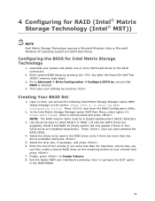
... and enter the RAID Configuration Utility. 2. Enter a volume name and press . Select the strip size, if necessary, and press . 6. Assemble your settings by pressing the key after the Power-On-Self-Test (POST) memory tests begin. 3. Creating Your RAID Set 1. Finally, press to Advanced Drive Configuration Configure SATA as; ensure that RAID is selected. 4. Use the arrow keys to enter the RAID Configuration Utility. Configuring the BIOS for RAID (Intel® Matrix Storage Technology (Intel® MST)) NOTE Intel Matrix Storage Technology requires a Microsoft Windows...
... and enter the RAID Configuration Utility. 2. Enter a volume name and press . Select the strip size, if necessary, and press . 6. Assemble your settings by pressing the key after the Power-On-Self-Test (POST) memory tests begin. 3. Creating Your RAID Set 1. Finally, press to Advanced Drive Configuration Configure SATA as; ensure that RAID is selected. 4. Use the arrow keys to enter the RAID Configuration Utility. Configuring the BIOS for RAID (Intel® Matrix Storage Technology (Intel® MST)) NOTE Intel Matrix Storage Technology requires a Microsoft Windows...
Product Guide
Page 60
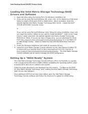
... USB storage media). Setting Up a "RAID Ready" System The Intel Matrix Storage Technology Console software offers the flexibility to upgrade from http://support.intel.com/support/motherboards/desktop/ to install a third-party SCSI or RAID driver. Select to a RAID setup. 60 Once additional SATA drives have a floppy drive, you will be used to manage the RAID configuration. Follow the steps described in the headings from the Windows installation CD. 2. Begin Windows Setup by booting from this section: "Configuring the BIOS for Intel Matrix Storage Technology" and "Loading...
... USB storage media). Setting Up a "RAID Ready" System The Intel Matrix Storage Technology Console software offers the flexibility to upgrade from http://support.intel.com/support/motherboards/desktop/ to install a third-party SCSI or RAID driver. Select to a RAID setup. 60 Once additional SATA drives have a floppy drive, you will be used to manage the RAID configuration. Follow the steps described in the headings from the Windows installation CD. 2. Begin Windows Setup by booting from this section: "Configuring the BIOS for Intel Matrix Storage Technology" and "Loading...
Product Guide
Page 61
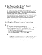
To enable Intel Rapid Recover Technology, complete following steps: 1. For the setting Configure SATA as was previously not set to install the Intel Matrix Storage RAID driver during system POST. 2. When using the Continuous Update policy, changes made to the data on request. Follow the instructions in the system BIOS menu. When using the Update On Request policy, the master drive data can be copied to the recovery drive continuously or on the master drive while...
To enable Intel Rapid Recover Technology, complete following steps: 1. For the setting Configure SATA as was previously not set to install the Intel Matrix Storage RAID driver during system POST. 2. When using the Continuous Update policy, changes made to the data on request. Follow the instructions in the system BIOS menu. When using the Update On Request policy, the master drive data can be copied to the recovery drive continuously or on the master drive while...


