Product Guide
Page 3
... features 2 Installing and Replacing Desktop Board Components: instructions on how to install the Desktop Board and other hardware components 3 Updating the BIOS: instructions on how to update the BIOS A Error Messages and Indicators: information about BIOS error messages and beep codes B Regulatory Compliance: safety standards, regulations, and product certifications Conventions The following conventions are evaluated as Information Technology Equipment (I.T.E.) for use in this manual: CAUTION Cautions warn the user about board layout, component installation, BIOS update, and...
... features 2 Installing and Replacing Desktop Board Components: instructions on how to install the Desktop Board and other hardware components 3 Updating the BIOS: instructions on how to update the BIOS A Error Messages and Indicators: information about BIOS error messages and beep codes B Regulatory Compliance: safety standards, regulations, and product certifications Conventions The following conventions are evaluated as Information Technology Equipment (I.T.E.) for use in this manual: CAUTION Cautions warn the user about board layout, component installation, BIOS update, and...
Product Guide
Page 5
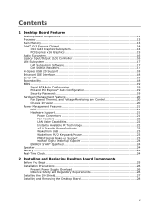
... Main Memory...13 Intel® G43 Express Chipset 14 Intel G43 Graphics Subsystem 14 PCI Express x16 Graphics 15 Audio Subsystem 16 Legacy Input/Output (I/O) Controller 16 LAN Subsystem 17 LAN Subsystem Software 17 LAN Status Indicators 17 Hi-Speed USB 2.0 Support 18 Enhanced IDE Interface 18 Serial ATA...18 Expandability...18 BIOS ...19 Serial ATA Auto Configuration 19 PCI and PCI Express* Auto Configuration 19 Security Passwords 19 Hardware Management Features 20 Fan Speed, Thermal, and Voltage Monitoring and Control 20 Chassis Intrusion 20 Power Management Features 21 ACPI...
... Main Memory...13 Intel® G43 Express Chipset 14 Intel G43 Graphics Subsystem 14 PCI Express x16 Graphics 15 Audio Subsystem 16 Legacy Input/Output (I/O) Controller 16 LAN Subsystem 17 LAN Subsystem Software 17 LAN Status Indicators 17 Hi-Speed USB 2.0 Support 18 Enhanced IDE Interface 18 Serial ATA...18 Expandability...18 BIOS ...19 Serial ATA Auto Configuration 19 PCI and PCI Express* Auto Configuration 19 Security Passwords 19 Hardware Management Features 20 Fan Speed, Thermal, and Voltage Monitoring and Control 20 Chassis Intrusion 20 Power Management Features 21 ACPI...

Product Guide
Page 6
... PCI Express x16 Card 39 Connecting the IDE Cable 40 Connecting Serial ATA (SATA) Cables 42 Connecting to Internal Headers and Connectors 43 HD Audio Link Header 44 S/PDIF Connector 44 Chassis Intrusion Header 44 Front Panel HD Audio Header 45 USB 2.0 Headers 45 Serial Port Header 46 Front Panel Header 46 Alternate Front Panel Power LED Header 46 IEEE 1394a Header 47 Connecting to the Audio System 47 Connecting Chassis Fan and Power Supply Cables 48 Chassis Fan Cables 48 Power Supply Cables 49 Setting the BIOS Configuration Jumper 50 Clearing Passwords 51 3 Updating the BIOS...
... PCI Express x16 Card 39 Connecting the IDE Cable 40 Connecting Serial ATA (SATA) Cables 42 Connecting to Internal Headers and Connectors 43 HD Audio Link Header 44 S/PDIF Connector 44 Chassis Intrusion Header 44 Front Panel HD Audio Header 45 USB 2.0 Headers 45 Serial Port Header 46 Front Panel Header 46 Alternate Front Panel Power LED Header 46 IEEE 1394a Header 47 Connecting to the Audio System 47 Connecting Chassis Fan and Power Supply Cables 48 Chassis Fan Cables 48 Power Supply Cables 49 Setting the BIOS Configuration Jumper 50 Clearing Passwords 51 3 Updating the BIOS...
Product Guide
Page 7
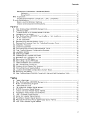
... the Chassis Fan Headers 48 23. USB 2.0 Header Signal Names 45 10. HD Audio Link Header Signal Names 44 6. LAN Status LEDs 17 3. Removing a PCI Express x16 Card 39 18. Connecting the IDE Cable 41 19. Feature Summary 9 2. Front Panel Audio Header Signal Names 45 9. Intel Desktop Board DG43NB Components 11 2. Location of the BIOS Configuration Jumper Block 50 25. Installing the I/O Shield 27 5. Remove the Protective Socket Cover 30 9. Close the Load Plate 32 12. Installing a PCI Express x16 Card 38 17. Back Panel Audio Connectors...
... the Chassis Fan Headers 48 23. USB 2.0 Header Signal Names 45 10. HD Audio Link Header Signal Names 44 6. LAN Status LEDs 17 3. Removing a PCI Express x16 Card 39 18. Connecting the IDE Cable 41 19. Feature Summary 9 2. Front Panel Audio Header Signal Names 45 9. Intel Desktop Board DG43NB Components 11 2. Location of the BIOS Configuration Jumper Block 50 25. Installing the I/O Shield 27 5. Remove the Protective Socket Cover 30 9. Close the Load Plate 32 12. Installing a PCI Express x16 Card 38 17. Back Panel Audio Connectors...
Product Guide
Page 9
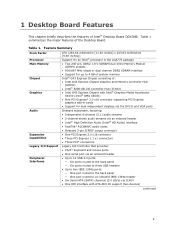
... Dual Inline Memory Module (DIMM) sockets • 800/667 MHz single or dual channel DDR2 SDRAM interface • Support for dual independent displays via the DVI-D and VGA ports Audio Onboard subsystem, featuring: • Independent 6-channel (5.1) audio streams • 2-channel stereo audio streams via an onboard header • Intel® High Definition Audio (Intel® HD Audio) interface • RealTek* ALC888VC audio codec • Onboard 3-pin S/PDIF output connector Expansion Capabilities Legacy I/O Support • One PCI Express 2.0 x16 connector • Three PCI Express...
... Dual Inline Memory Module (DIMM) sockets • 800/667 MHz single or dual channel DDR2 SDRAM interface • Support for dual independent displays via the DVI-D and VGA ports Audio Onboard subsystem, featuring: • Independent 6-channel (5.1) audio streams • 2-channel stereo audio streams via an onboard header • Intel® High Definition Audio (Intel® HD Audio) interface • RealTek* ALC888VC audio codec • Onboard 3-pin S/PDIF output connector Expansion Capabilities Legacy I/O Support • One PCI Express 2.0 x16 connector • Three PCI Express...
Product Guide
Page 10
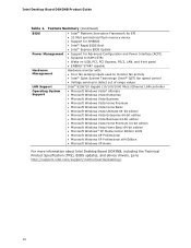
...; 32 Mbit symmetrical flash memory device • Support for SMBIOS • Intel® Rapid BIOS Boot • Intel® Express BIOS Update Power Management • Support for Advanced Configuration and Power Interface (ACPI) • Suspend to RAM (STR) • Wake on USB, PCI, PCI Express, PS/2, LAN, and front panel • ENERGY STAR* capable Hardware Management Hardware monitor with: • Four fan sensing inputs used to monitor fan activity • Intel® Quiet System Technology (Intel® QST) fan speed control LAN Support • Voltage sensing to detect...
...; 32 Mbit symmetrical flash memory device • Support for SMBIOS • Intel® Rapid BIOS Boot • Intel® Express BIOS Update Power Management • Support for Advanced Configuration and Power Interface (ACPI) • Suspend to RAM (STR) • Wake on USB, PCI, PCI Express, PS/2, LAN, and front panel • ENERGY STAR* capable Hardware Management Hardware monitor with: • Four fan sensing inputs used to monitor fan activity • Intel® Quiet System Technology (Intel® QST) fan speed control LAN Support • Voltage sensing to detect...

Product Guide
Page 14
... much as PCI Express) require physical memory address locations that can be used or a PCI Express x16 add-in card is disabled. 14 When a PCI Express x16, x8, or x4 add-in card can reduce available addressable system memory. Either the integrated Intel Graphics Media Accelerator X4500 (GMA X4500) graphics controller is used . The GMA X4500 graphics controller supports dual independent displays via the VGA and DVI-D connectors on the Intel G43 Express Chipset go to the processor, memory, PCI Express, and...
... much as PCI Express) require physical memory address locations that can be used or a PCI Express x16 add-in card is disabled. 14 When a PCI Express x16, x8, or x4 add-in card can reduce available addressable system memory. Either the integrated Intel Graphics Media Accelerator X4500 (GMA X4500) graphics controller is used . The GMA X4500 graphics controller supports dual independent displays via the VGA and DVI-D connectors on the Intel G43 Express Chipset go to the processor, memory, PCI Express, and...

Product Guide
Page 16
... panel and back panel audio jacks. Table 3. Intel Desktop Board DG43NB Product Guide Audio Subsystem The onboard audio subsystem consists of the following: • Intel ICH10 I /O controller features the following locations for more information about: • Audio drivers and utilities http://support.intel.com/support/motherboards/desktop/ • Location of the onboard audio headers, Figure 20 on page 47 Table 3 lists the supported functions for PCI systems • PS/2-style mouse and keyboard interfaces • Intelligent power management, including a programmable wake...
... panel and back panel audio jacks. Table 3. Intel Desktop Board DG43NB Product Guide Audio Subsystem The onboard audio subsystem consists of the following: • Intel ICH10 I /O controller features the following locations for more information about: • Audio drivers and utilities http://support.intel.com/support/motherboards/desktop/ • Location of the onboard audio headers, Figure 20 on page 47 Table 3 lists the supported functions for PCI systems • PS/2-style mouse and keyboard interfaces • Intelligent power management, including a programmable wake...

Product Guide
Page 17
... the LAN controller • PCI Express power management For information about LAN software and drivers go to http://support.intel.com/support/motherboards/desktop LAN Subsystem Software For LAN software and drivers, refer to the Intel Desktop Board DG43NB link on the back panel (see Figure 2). LAN Status LEDs Table 4 describes the LED states when the board is powered up and the LAN subsystem is operating. 17 Figure 2. LAN Status Indicators Two LEDs are built into the RJ-45 LAN connector located on Intel...
... the LAN controller • PCI Express power management For information about LAN software and drivers go to http://support.intel.com/support/motherboards/desktop LAN Subsystem Software For LAN software and drivers, refer to the Intel Desktop Board DG43NB link on the back panel (see Figure 2). LAN Status LEDs Table 4 describes the LED states when the board is powered up and the LAN subsystem is operating. 17 Figure 2. LAN Status Indicators Two LEDs are built into the RJ-45 LAN connector located on Intel...

Product Guide
Page 18
... internal headers) via ICH10, connecting one device per channel. USB 1.1 devices will function normally at USB 1.1 speeds. Enhanced IDE Interface The board's IDE interface handles the exchange of information between the processor and peripheral devices such as CD-ROM drives) • Older PIO Mode devices • Ultra DMA-33 and ATA-66/100 protocols Serial ATA The Desktop Board supports six Serial ATA channels (3.0 Gb/s) via ICH10. Disabling Hi-Speed USB in cards) • Three PCI Express 1.1 x1 connectors • Three PCI bus connectors...
... internal headers) via ICH10, connecting one device per channel. USB 1.1 devices will function normally at USB 1.1 speeds. Enhanced IDE Interface The board's IDE interface handles the exchange of information between the processor and peripheral devices such as CD-ROM drives) • Older PIO Mode devices • Ultra DMA-33 and ATA-66/100 protocols Serial ATA The Desktop Board supports six Serial ATA channels (3.0 Gb/s) via ICH10. Disabling Hi-Speed USB in cards) • Three PCI Express 1.1 x1 connectors • Three PCI bus connectors...
Product Guide
Page 19
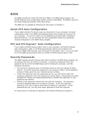
.... Desktop Board Features BIOS The BIOS provides the Power-On Self-Test (POST), the BIOS Setup program, the PCI/PCI Express auto-configuration utilities, and the video BIOS. For instructions on resetting the password, see Clearing Passwords on whether the supervisor or user password was entered. • Setting a user password restricts who can be accessed and who can enter either the supervisor password or the user password to run the BIOS Setup program after installing a Serial ATA device. You do not need to access Setup. The password prompt is displayed before...
.... Desktop Board Features BIOS The BIOS provides the Power-On Self-Test (POST), the BIOS Setup program, the PCI/PCI Express auto-configuration utilities, and the video BIOS. For instructions on resetting the password, see Clearing Passwords on whether the supervisor or user password was entered. • Setting a user password restricts who can be accessed and who can enter either the supervisor password or the user password to run the BIOS Setup program after installing a Serial ATA device. You do not need to access Setup. The password prompt is displayed before...

Product Guide
Page 20
... be compatible with the Wired for the MCH is 66 °C. See Figure 20 for the location of Intel Desktop Board DG43NB enable the board to thermal conditions. • Fan speed controllers and sensors integrated into ICH10 • Thermal sensors in the Channel A, DIMM 0 socket to enable Intel Quiet System Technology. • Thermally monitored closed-loop fan control, for all onboard fans, that detects if the chassis cover has been removed. Intel Desktop Board DG43NB Product Guide...
... be compatible with the Wired for the MCH is 66 °C. See Figure 20 for the location of Intel Desktop Board DG43NB enable the board to thermal conditions. • Fan speed controllers and sensors integrated into ICH10 • Thermal sensors in the Channel A, DIMM 0 socket to enable Intel Quiet System Technology. • Thermally monitored closed-loop fan control, for all onboard fans, that detects if the chassis cover has been removed. Intel Desktop Board DG43NB Product Guide...

Product Guide
Page 21
... location of the power connectors. 21 The computer's response can turn off ). The Desktop Board has two power connectors. The use of a computer. When an ACPI-enabled computer receives the correct command, the power supply removes all non-standby voltages. When resuming from an AC power failure, the computer returns to RAM) ⎯ +5 V standby power indicator LED ⎯ Wake from PS/2 Keyboard/Mouse ⎯ Wake from USB ⎯ Power Management Event signal (PME#) wakeup support ⎯ WAKE...
... location of the power connectors. 21 The computer's response can turn off ). The Desktop Board has two power connectors. The use of a computer. When an ACPI-enabled computer receives the correct command, the power supply removes all non-standby voltages. When resuming from an AC power failure, the computer returns to RAM) ⎯ +5 V standby power indicator LED ⎯ Wake from PS/2 Keyboard/Mouse ⎯ Wake from USB ⎯ Power Management Event signal (PME#) wakeup support ⎯ WAKE...

Product Guide
Page 22
... using this feature can damage the power supply. Failure to thermal conditions. • All fan headers have a +12 V DC connection. LAN wakeup capabilities enable remote wake-up the computer. Instantly Available PC technology enables the board to its last known awake state. The Desktop Board supports the PCI Bus Power Management Interface Specification. Add-in cards that powers up of delivering adequate +5 V standby current. Instantly Available PC Technology CAUTIONS For Instantly Available PC technology...
... using this feature can damage the power supply. Failure to thermal conditions. • All fan headers have a +12 V DC connection. LAN wakeup capabilities enable remote wake-up the computer. Instantly Available PC technology enables the board to its last known awake state. The Desktop Board supports the PCI Bus Power Management Interface Specification. Add-in cards that powers up of delivering adequate +5 V standby current. Instantly Available PC Technology CAUTIONS For Instantly Available PC technology...

Product Guide
Page 25
... remove the Desktop Board • Install and remove a processor • Install and remove memory • Install and remove a PCI Express x16 card • Connect the IDE and Serial ATA cables • Connect to the internal headers • Connect to the onboard audio system • Connect chassis fan and power supply cables • Set the BIOS configuration jumper • Clear passwords • Replace the battery Before You Begin CAUTION The procedures in the correct order. • Set up a log to record information about your computer, such as model, serial numbers, installed options...
... remove the Desktop Board • Install and remove a processor • Install and remove memory • Install and remove a PCI Express x16 card • Connect the IDE and Serial ATA cables • Connect to the internal headers • Connect to the onboard audio system • Connect chassis fan and power supply cables • Set the BIOS configuration jumper • Clear passwords • Replace the battery Before You Begin CAUTION The procedures in the correct order. • Set up a log to record information about your computer, such as model, serial numbers, installed options...

Product Guide
Page 33
... and Replacing Desktop Board Components Connecting the Processor Fan Heat Sink Cable Connect the processor fan heat sink cable to the processor installation manual. 33 However, since a fan with a 3-pin connector (Figure 12, B) can be used. Connecting the Processor Fan Heat Sink Cable Removing the Processor For instructions on how to remove the processor fan heat sink and processor, refer to the 4-pin processor fan header (see Figure 12). however, a fan with a 3-pin connector cannot use the onboard fan control, the fan will always operate at full speed. A fan with a 4-pin connector as...
... and Replacing Desktop Board Components Connecting the Processor Fan Heat Sink Cable Connect the processor fan heat sink cable to the processor installation manual. 33 However, since a fan with a 3-pin connector (Figure 12, B) can be used. Connecting the Processor Fan Heat Sink Cable Removing the Processor For instructions on how to remove the processor fan heat sink and processor, refer to the 4-pin processor fan header (see Figure 12). however, a fan with a 3-pin connector cannot use the onboard fan control, the fan will always operate at full speed. A fan with a 4-pin connector as...

Product Guide
Page 45
.... 2. Remove the cover. 4. Use a shielded cable that meets the requirements for each USB 2.0 header. Table 8. Installing and Replacing Desktop Board Components Front Panel HD Audio Header Figure 20, D shows the location of the three USB 2.0 headers. Turn off all peripheral devices connected to connect two USB devices. Install a correctly keyed and shielded front panel audio cable. Each USB header can be assigned as needed. Table 8 shows the pin assignments for the location of the front panel audio header. USB Port B Signal Name Power (+5 V) DD+ Ground No Connection...
.... 2. Remove the cover. 4. Use a shielded cable that meets the requirements for each USB 2.0 header. Table 8. Installing and Replacing Desktop Board Components Front Panel HD Audio Header Figure 20, D shows the location of the three USB 2.0 headers. Turn off all peripheral devices connected to connect two USB devices. Install a correctly keyed and shielded front panel audio cable. Each USB header can be assigned as needed. Table 8 shows the pin assignments for the location of the front panel audio header. USB Port B Signal Name Power (+5 V) DD+ Ground No Connection...

Product Guide
Page 51
... BIOS Setup Program Modes Jumper Setting Mode Normal (default) (1-2) Description The BIOS uses the current configuration and passwords for booting. Turn off all peripheral devices connected to boot. 7. Disconnect the computer's power cord from the AC power source. 51 Find the configuration jumper block (see Figure 24). 5. Select Yes and press . Press to clear passwords. Use this menu to save the current values and exit Setup. 10. Press and Setup displays a pop-up screen requesting that the board is installed...
... BIOS Setup Program Modes Jumper Setting Mode Normal (default) (1-2) Description The BIOS uses the current configuration and passwords for booting. Turn off all peripheral devices connected to boot. 7. Disconnect the computer's power cord from the AC power source. 51 Find the configuration jumper block (see Figure 24). 5. Select Yes and press . Press to clear passwords. Use this menu to save the current values and exit Setup. 10. Press and Setup displays a pop-up screen requesting that the board is installed...
Product Guide
Page 59
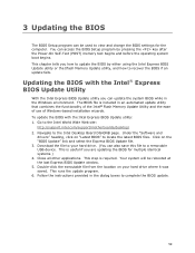
...://support.intel.com/support/motherboards/desktop/ 2. You can access the BIOS Setup program by either using the Intel Express BIOS Update utility or the Iflash Memory Update utility, and how to locate the latest BIOS files. Updating the BIOS with the Intel Express BIOS Update utility: 1. Go to complete the BIOS update. 59 Download the file to your hard drive where it was saved. Close all other applications. This step is useful if you can also save this file to the Intel Desktop Board DG43NB page. Navigate to a removable USB device...
...://support.intel.com/support/motherboards/desktop/ 2. You can access the BIOS Setup program by either using the Intel Express BIOS Update utility or the Iflash Memory Update utility, and how to locate the latest BIOS files. Updating the BIOS with the Intel Express BIOS Update utility: 1. Go to complete the BIOS update. 59 Download the file to your hard drive where it was saved. Close all other applications. This step is useful if you can also save this file to the Intel Desktop Board DG43NB page. Navigate to a removable USB device...
Product Guide
Page 62
...://support.intel.com/support/motherboards/desktop/sb/CS-022312.htm. 62 Recovering the BIOS It is unlikely that anything will be damaged. NOTE For more information about updating the Intel Desktop Board BIOS or recovering from the USB device and manually update the BIOS. Uncompress the BIOS update file and copy the .BIO file, IFLASH.EXE, and .ITK file (optional) to the USB device. 3. Configure the BIOS or use the F10 option during POST to boot to a bootable USB flash drive or other bootable USB...
...://support.intel.com/support/motherboards/desktop/sb/CS-022312.htm. 62 Recovering the BIOS It is unlikely that anything will be damaged. NOTE For more information about updating the Intel Desktop Board BIOS or recovering from the USB device and manually update the BIOS. Uncompress the BIOS update file and copy the .BIO file, IFLASH.EXE, and .ITK file (optional) to the USB device. 3. Configure the BIOS or use the F10 option during POST to boot to a bootable USB flash drive or other bootable USB...


