Product Guide
Page 3
... use in personal computers (PC) for Intel® Desktop Board DG41TY. may not be supported without further evaluation by Intel. Document Organization The chapters in this product for other PC or embedded non-PC applications or other hardware components 3 Updating the BIOS: instructions on how to update the BIOS A Error Messages and Indicators: information about BIOS error messages and beep codes B Regulatory Compliance: information about board layout, component installation, BIOS update...
... use in personal computers (PC) for Intel® Desktop Board DG41TY. may not be supported without further evaluation by Intel. Document Organization The chapters in this product for other PC or embedded non-PC applications or other hardware components 3 Updating the BIOS: instructions on how to update the BIOS A Error Messages and Indicators: information about BIOS error messages and beep codes B Regulatory Compliance: information about board layout, component installation, BIOS update...
Product Guide
Page 5
... IDE Auto Configuration 19 PCI* and PCI Express* Auto Configuration 19 Security Passwords 20 Hardware Management Features 20 Hardware Monitoring and Fan Speed Control 21 Chassis Intrusion 21 Power Management Features 21 ACPI ...21 Hardware Support 22 Power Connectors 22 Fan Headers 22 LAN Wake Capabilities 22 Instantly Available PC Technology 23 +5 V Standby Power Indicator LED 23 Wake from USB 24 PME# Signal Wake-up Support 24 WAKE# Signal Wake-up Support 24 ENERGY STAR* Capable 24 Speaker...24 Battery ...24 Real-Time Clock 25 2 Installing and Replacing Desktop Board...
... IDE Auto Configuration 19 PCI* and PCI Express* Auto Configuration 19 Security Passwords 20 Hardware Management Features 20 Hardware Monitoring and Fan Speed Control 21 Chassis Intrusion 21 Power Management Features 21 ACPI ...21 Hardware Support 22 Power Connectors 22 Fan Headers 22 LAN Wake Capabilities 22 Instantly Available PC Technology 23 +5 V Standby Power Indicator LED 23 Wake from USB 24 PME# Signal Wake-up Support 24 WAKE# Signal Wake-up Support 24 ENERGY STAR* Capable 24 Speaker...24 Battery ...24 Real-Time Clock 25 2 Installing and Replacing Desktop Board...
Product Guide
Page 6
...Front Panel Audio Header 46 Serial Port Header 47 HD Audio Link Header 47 Chassis Intrusion Header 48 Front Panel Header 48 Alternate Front Panel Power LED Header 49 USB 2.0 Headers 49 Connecting to the Back Panel Audio Connectors 50 Connecting Chassis Fan and Power Supply Cables 51 Connecting Chassis Fan Cables 51 Connecting Supply Power Cables 52 Setting the BIOS Configuration Jumper 53 Clearing Passwords 54 Replacing the Battery 55 3 Updating the BIOS Updating the BIOS with the Intel® Express BIOS Update Utility 61 Updating the BIOS with the ISO Image BIOS Update File or...
...Front Panel Audio Header 46 Serial Port Header 47 HD Audio Link Header 47 Chassis Intrusion Header 48 Front Panel Header 48 Alternate Front Panel Power LED Header 49 USB 2.0 Headers 49 Connecting to the Back Panel Audio Connectors 50 Connecting Chassis Fan and Power Supply Cables 51 Connecting Chassis Fan Cables 51 Connecting Supply Power Cables 52 Setting the BIOS Configuration Jumper 53 Clearing Passwords 54 Replacing the Battery 55 3 Updating the BIOS Updating the BIOS with the Intel® Express BIOS Update Utility 61 Updating the BIOS with the ISO Image BIOS Update File or...
Product Guide
Page 7
... Channel Memory Configuration Example 36 14. Installing a DIMM 38 16. Installing a PCI Express x16 Card 40 17. Feature Summary 9 2. Alternate Front Panel Power LED Header 49 14. Intel Desktop Board DG41TY Mounting Screw Hole Locations 30 6. Connecting the Processor Fan Heat Sink Cable to the Processor Fan Header ..........35 13. LAN Connector LEDs 18 5. Front Panel Header 48 13. Beep Codes 65 17. Installing the I/O Shield 29 5. Lift the Load Plate 32 8. Connecting a Serial ATA Cable 44 21. Jumper Settings for Intel HD Audio 46 8. Serial Port...
... Channel Memory Configuration Example 36 14. Installing a DIMM 38 16. Installing a PCI Express x16 Card 40 17. Feature Summary 9 2. Alternate Front Panel Power LED Header 49 14. Intel Desktop Board DG41TY Mounting Screw Hole Locations 30 6. Connecting the Processor Fan Heat Sink Cable to the Processor Fan Header ..........35 13. LAN Connector LEDs 18 5. Front Panel Header 48 13. Beep Codes 65 17. Installing the I/O Shield 29 5. Lift the Load Plate 32 8. Connecting a Serial ATA Cable 44 21. Jumper Settings for Intel HD Audio 46 8. Serial Port...
Product Guide
Page 9
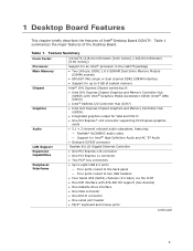
... back panel ― Four ports routed to two USB headers • Four Serial ATA (SATA) channels (3.0 Gb/s) via the ICH7 • One IDE interface with ATA-66/100 support (two devices) • One diskette drive interface • One VGA connector • One DVI-D connector • One serial port header • PS/2* keyboard and mouse ports continued 9 Table 1 summarizes the major features of : • Intel G41 Express Chipset Graphics and Memory Controller Hub (GMCH) with Intel® Graphics...
... back panel ― Four ports routed to two USB headers • Four Serial ATA (SATA) channels (3.0 Gb/s) via the ICH7 • One IDE interface with ATA-66/100 support (two devices) • One diskette drive interface • One VGA connector • One DVI-D connector • One serial port header • PS/2* keyboard and mouse ports continued 9 Table 1 summarizes the major features of : • Intel G41 Express Chipset Graphics and Memory Controller Hub (GMCH) with Intel® Graphics...
Product Guide
Page 10
... symmetrical flash memory device • Support for SMBIOS • Intel® Rapid BIOS Boot • Intel® Express BIOS Update Power Management • Support for Advanced Configuration and Power Interface (ACPI) • Suspend to RAM (STR) • Wake on USB, PCI Express, LAN, and front panel • ENERGY STAR* capable Hardware Monitor • Voltage sense to detect out of range power supply voltages • Thermal sense to detect out of range temperatures • Three fan headers • Three fan sense inputs to monitor fan speed...
... symmetrical flash memory device • Support for SMBIOS • Intel® Rapid BIOS Boot • Intel® Express BIOS Update Power Management • Support for Advanced Configuration and Power Interface (ACPI) • Suspend to RAM (STR) • Wake on USB, PCI Express, LAN, and front panel • ENERGY STAR* capable Hardware Monitor • Voltage sense to detect out of range power supply voltages • Thermal sense to detect out of range temperatures • Three fan headers • Three fan sense inputs to monitor fan speed...
Product Guide
Page 13
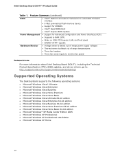
... following links for more information about : • Intel Desktop Board DG41TY http://www.intel.com/design/motherbd http://support.intel.com/support/motherboards/desktop • Supported processors http://processormatch.intel.com • Audio software and utilities http://www.intel.com/design/motherbd • LAN software and drivers http://www.intel.com/design/motherbd Processor CAUTION Failure to use an appropriate power supply and/or not connecting the 12 V (2 x 2 pin) power connector to the Desktop Board may result in damage to the...
... following links for more information about : • Intel Desktop Board DG41TY http://www.intel.com/design/motherbd http://support.intel.com/support/motherboards/desktop • Supported processors http://processormatch.intel.com • Audio software and utilities http://www.intel.com/design/motherbd • LAN software and drivers http://www.intel.com/design/motherbd Processor CAUTION Failure to use an appropriate power supply and/or not connecting the 12 V (2 x 2 pin) power connector to the Desktop Board may result in damage to the...
Product Guide
Page 16
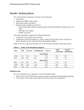
... audio (using the back panel audio connectors) and 2-channel stereo (using the front panel audio header) Table 3 lists the supported functions for more information about: • Audio drivers and utilities http://support.intel.com/support/motherboards/desktop/ • The location of the following: • Intel® ICH7 • Realtek ALC888VC audio codec • Back panel audio connectors • Onboard audio headers/connectors: ⎯ Front panel audio header supporting both Intel High Definition Audio and AC '97 Audio ⎯ HD Audio Link header ⎯ S/PDIF connector The audio...
... audio (using the back panel audio connectors) and 2-channel stereo (using the front panel audio header) Table 3 lists the supported functions for more information about: • Audio drivers and utilities http://support.intel.com/support/motherboards/desktop/ • The location of the following: • Intel® ICH7 • Realtek ALC888VC audio codec • Back panel audio connectors • Onboard audio headers/connectors: ⎯ Front panel audio header supporting both Intel High Definition Audio and AC '97 Audio ⎯ HD Audio Link header ⎯ S/PDIF connector The audio...
Product Guide
Page 17
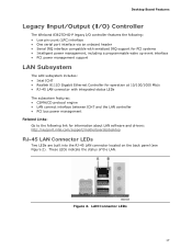
...; RJ-45 LAN connector with integrated status LEDs The subsystem features: • CSMA/CD protocol engine • LAN connect interface between ICH7 and the LAN controller • PCI bus power management Related Links: Go to the following link for information about LAN software and drivers: http://support.intel.com/support/motherboards/desktop RJ-45 LAN Connector LEDs Two LEDs are built into the RJ-45 LAN connector located on the back panel (see Figure 2). LAN Connector LEDs 17 Figure...
...; RJ-45 LAN connector with integrated status LEDs The subsystem features: • CSMA/CD protocol engine • LAN connect interface between ICH7 and the LAN controller • PCI bus power management Related Links: Go to the following link for information about LAN software and drivers: http://support.intel.com/support/motherboards/desktop RJ-45 LAN Connector LEDs Two LEDs are built into the RJ-45 LAN connector located on the back panel (see Figure 2). LAN Connector LEDs 17 Figure...
Product Guide
Page 18
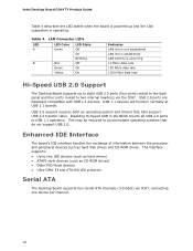
USB 2.0 ports are backward compatible with USB 1.1 devices. This may be required to two IDE devices (such as hard drives) • ATAPI-style devices (such as hard disk drives and CD-ROM drives. LAN Connector LEDs LED A B LED Color Green N/A Green Yellow LED State Off On Blinking Off On On Indicates LAN link is not established LAN link is established LAN activity is operating. Intel Desktop Board DG41TY Product Guide Table 4 describes the LED states when the board is powered up and...
USB 2.0 ports are backward compatible with USB 1.1 devices. This may be required to two IDE devices (such as hard drives) • ATAPI-style devices (such as hard disk drives and CD-ROM drives. LAN Connector LEDs LED A B LED Color Green N/A Green Yellow LED State Off On Blinking Off On On Indicates LAN link is not established LAN link is established LAN activity is operating. Intel Desktop Board DG41TY Product Guide Table 4 describes the LED states when the board is powered up and...
Product Guide
Page 19
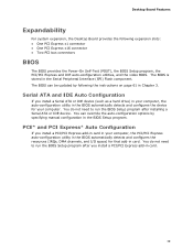
...-in the BIOS automatically detects and configures the device for your computer, the auto-configuration utility in card. You can be updated by specifying manual configuration in the Serial Peripheral Interface (SPI) Flash component. The BIOS can override the auto-configuration options by following expansion slots: • One PCI Express x1 connector • One PCI Express x16 connector • Two PCI bus connectors BIOS The BIOS provides the Power-On Self-Test (POST), the BIOS Setup program, the PCI/PCI Express and IDE auto-configuration utilities, and the video BIOS.
...-in the BIOS automatically detects and configures the device for your computer, the auto-configuration utility in card. You can be updated by specifying manual configuration in the Serial Peripheral Interface (SPI) Flash component. The BIOS can override the auto-configuration options by following expansion slots: • One PCI Express x1 connector • One PCI Express x16 connector • Two PCI bus connectors BIOS The BIOS provides the Power-On Self-Test (POST), the BIOS Setup program, the PCI/PCI Express and IDE auto-configuration utilities, and the video BIOS.
Product Guide
Page 22
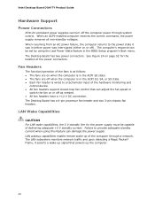
... fan header is wired to a tachometer input of the computer through system control. Intel Desktop Board DG41TY Product Guide Hardware Support Power Connectors ATX12V-compliant power supplies can turn off the computer power through a network. LAN wakeup capabilities enable remote wake-up the computer. 22 Failure to the power state it asserts a wake-up signal that powers up of the hardware monitoring and control device. • All fan headers support closed-loop fan control that can adjust the fan speed or switch the fan on...
... fan header is wired to a tachometer input of the computer through system control. Intel Desktop Board DG41TY Product Guide Hardware Support Power Connectors ATX12V-compliant power supplies can turn off the computer power through a network. LAN wakeup capabilities enable remote wake-up the computer. 22 Failure to the power state it asserts a wake-up signal that powers up of the hardware monitoring and control device. • All fan headers support closed-loop fan control that can adjust the fan speed or switch the fan on...
Product Guide
Page 23
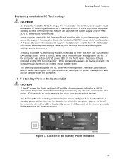
.... Power supplies used to wake the computer. +5 V Standby Power Indicator LED CAUTION If the AC power has been switched off and the standby power indicator is standby power still present on the front panel, the sleep state is still present at the memory module sockets and the PCI bus connectors. Add-in cards that support this Desktop Board must be used with this specification can damage the power supply and/or effect ACPI S3 sleep state functionality. Failure...
.... Power supplies used to wake the computer. +5 V Standby Power Indicator LED CAUTION If the AC power has been switched off and the standby power indicator is standby power still present on the front panel, the sleep state is still present at the memory module sockets and the PCI bus connectors. Add-in cards that support this Desktop Board must be used with this specification can damage the power supply and/or effect ACPI S3 sleep state functionality. Failure...
Product Guide
Page 27
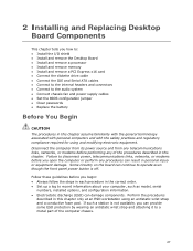
... chapter. 2 Installing and Replacing Desktop Board Components This chapter tells you how to: • Install the I/O shield • Install and remove the Desktop Board • Install and remove a processor • Install and remove memory • Install and remove a PCI Express x16 card • Connect the diskette drive cable • Connect the IDE and Serial ATA cables • Connect to the internal headers and connectors • Connect to a metal part of the procedures described in this chapter only at an ESD workstation using and modifying...
... chapter. 2 Installing and Replacing Desktop Board Components This chapter tells you how to: • Install the I/O shield • Install and remove the Desktop Board • Install and remove a processor • Install and remove memory • Install and remove a PCI Express x16 card • Connect the diskette drive cable • Connect the IDE and Serial ATA cables • Connect to the internal headers and connectors • Connect to a metal part of the procedures described in this chapter only at an ESD workstation using and modifying...
Product Guide
Page 35
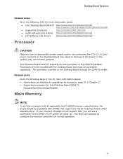
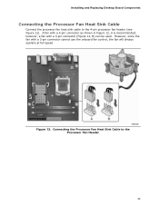
Installing and Replacing Desktop Board Components Connecting the Processor Fan Heat Sink Cable Connect the processor fan heat sink cable to the Processor Fan Header 35 A fan with a 3-pin connector (Figure 12, B) can be used. however, a fan with a 4-pin connector as shown in Figure 12, A is recommended; Figure 12. However, since the fan with a 3-pin connector cannot use the onboard fan control, the fan will always operate at full speed. Connecting the Processor Fan Heat Sink Cable to the 4-pin processor fan header (see Figure 12).
Installing and Replacing Desktop Board Components Connecting the Processor Fan Heat Sink Cable Connect the processor fan heat sink cable to the Processor Fan Header 35 A fan with a 3-pin connector (Figure 12, B) can be used. however, a fan with a 4-pin connector as shown in Figure 12, A is recommended; Figure 12. However, since the fan with a 3-pin connector cannot use the onboard fan control, the fan will always operate at full speed. Connecting the Processor Fan Heat Sink Cable to the 4-pin processor fan header (see Figure 12).

Product Guide
Page 51
Figure 23 shows the location of the Chassis Fan Headers 51 Figure 23. Installing and Replacing Desktop Board Components Connecting Chassis Fan and Power Supply Cables Connecting Chassis Fan Cables Connect chassis fan cables to the 3-pin chassis fan headers on the Desktop Board. Location of the chassis fan headers.
Figure 23 shows the location of the Chassis Fan Headers 51 Figure 23. Installing and Replacing Desktop Board Components Connecting Chassis Fan and Power Supply Cables Connecting Chassis Fan Cables Connect chassis fan cables to the 3-pin chassis fan headers on the Desktop Board. Location of the chassis fan headers.
Product Guide
Page 53
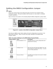
...be done in the BIOS Setup program. Jumper Settings for the BIOS Setup Program Modes Jumper Setting Mode Normal (default) (1-2) Description The BIOS uses the current configuration and passwords for the BIOS Setup program modes. Figure 25 shows the location of the BIOS Configuration Jumper Block The three-pin BIOS jumper block enables all board configurations to clear passwords. Installing and Replacing Desktop Board Components Setting the BIOS Configuration Jumper NOTE Always turn off the power and unplug the power cord from the computer before moving the jumper. Table 15 shows...
...be done in the BIOS Setup program. Jumper Settings for the BIOS Setup Program Modes Jumper Setting Mode Normal (default) (1-2) Description The BIOS uses the current configuration and passwords for the BIOS Setup program modes. Figure 25 shows the location of the BIOS Configuration Jumper Block The three-pin BIOS jumper block enables all board configurations to clear passwords. Installing and Replacing Desktop Board Components Setting the BIOS Configuration Jumper NOTE Always turn off the power and unplug the power cord from the computer before moving the jumper. Table 15 shows...
Product Guide
Page 54
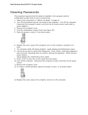
... peripheral devices connected to the computer. The computer starts the Setup program. Select Yes and press . Intel Desktop Board DG41TY Product Guide Clearing Passwords This procedure assumes that you confirm clearing the password. Use the arrow keys to save the current values and exit Setup. 10. Turn off the computer. Replace the cover, plug in the computer, turn on pins 1-2 as shown below . 13. Remove the computer cover. 4. Replace the cover, plug in...
... peripheral devices connected to the computer. The computer starts the Setup program. Select Yes and press . Intel Desktop Board DG41TY Product Guide Clearing Passwords This procedure assumes that you confirm clearing the password. Use the arrow keys to save the current values and exit Setup. 10. Turn off the computer. Replace the cover, plug in the computer, turn on pins 1-2 as shown below . 13. Remove the computer cover. 4. Replace the cover, plug in...
Product Guide
Page 61
...: http://support.intel.com/support/motherboards/desktop/ 2. This chapter tells you can access the BIOS Setup program by either using the Intel Express BIOS Update utility or the Iflash Memory Update utility, and how to recover the BIOS if an update fails. Go to complete the BIOS update. 61 Navigate to view and change the BIOS settings for multiple identical systems.) 4. 3 Updating the BIOS The BIOS Setup program can also save this file to a removable USB device. You can update the system BIOS while...
...: http://support.intel.com/support/motherboards/desktop/ 2. This chapter tells you can access the BIOS Setup program by either using the Intel Express BIOS Update utility or the Iflash Memory Update utility, and how to recover the BIOS if an update fails. Go to complete the BIOS update. 61 Navigate to view and change the BIOS settings for multiple identical systems.) 4. 3 Updating the BIOS The BIOS Setup program can also save this file to a removable USB device. You can update the system BIOS while...
Product Guide
Page 64
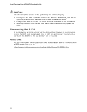
... will be damaged. however, if an interruption occurs, the BIOS could be required. Uncompress the BIOS update file and copy the .BIO file, IFLASH.EXE, and .ITK file (optional) to the USB device. 3. Intel Desktop Board DG41TY Product Guide CAUTION Do not interrupt the process or the system may not function properly. 1. Configure the BIOS or use the F10 option during POST to boot to a bootable USB flash drive or other bootable USB media. 2.
... will be damaged. however, if an interruption occurs, the BIOS could be required. Uncompress the BIOS update file and copy the .BIO file, IFLASH.EXE, and .ITK file (optional) to the USB device. 3. Intel Desktop Board DG41TY Product Guide CAUTION Do not interrupt the process or the system may not function properly. 1. Configure the BIOS or use the F10 option during POST to boot to a bootable USB flash drive or other bootable USB media. 2.


