
Product Guide
Page 3
... This Product Guide gives information about BIOS error messages and beep codes B Regulatory Compliance: safety and EMC regulations and product certifications Conventions The following conventions are arranged as follows: 1 Desktop Board Features: a summary of product features 2 Installing and Replacing Desktop Board Components: instructions on how to install the Desktop Board and other environments, such as Information Technology Equipment (I.T.E.) for use in personal computers (PC) for installation in this...
... This Product Guide gives information about BIOS error messages and beep codes B Regulatory Compliance: safety and EMC regulations and product certifications Conventions The following conventions are arranged as follows: 1 Desktop Board Features: a summary of product features 2 Installing and Replacing Desktop Board Components: instructions on how to install the Desktop Board and other environments, such as Information Technology Equipment (I.T.E.) for use in personal computers (PC) for installation in this...

Product Guide
Page 5
... 10 Processor ...12 Main Memory...12 Intel® 945GC Express Chipset 13 Onboard Audio Subsystem 13 Input/Output (I/O) Controller 14 LAN Subsystem 15 LAN Subsystem Software 15 LAN Status LEDs 15 Hi-Speed USB 2.0 Support 16 Enhanced IDE Interface 16 Serial ATA...16 Expandability...16 BIOS ...17 IDE Auto Configuration 17 PCI Auto Configuration 17 Security Passwords 17 Power Management Features 18 ACPI ...18 Hardware Support 18 Power Connectors 18 Fan Headers 18 +5 V Standby Power Indicator LED 19 LAN Wake Capabilities 20 Wake from USB 20 Wake from PS/2 Keyboard/Mouse...
... 10 Processor ...12 Main Memory...12 Intel® 945GC Express Chipset 13 Onboard Audio Subsystem 13 Input/Output (I/O) Controller 14 LAN Subsystem 15 LAN Subsystem Software 15 LAN Status LEDs 15 Hi-Speed USB 2.0 Support 16 Enhanced IDE Interface 16 Serial ATA...16 Expandability...16 BIOS ...17 IDE Auto Configuration 17 PCI Auto Configuration 17 Security Passwords 17 Power Management Features 18 ACPI ...18 Hardware Support 18 Power Connectors 18 Fan Headers 18 +5 V Standby Power Indicator LED 19 LAN Wake Capabilities 20 Wake from USB 20 Wake from PS/2 Keyboard/Mouse...
Product Guide
Page 6
... Desktop Board DG945GCLF Product Guide Connecting Power Supply Cables 33 Setting the BIOS Configuration Jumper 34 Clearing Passwords 35 Replacing the Battery 36 3 Updating the BIOS Updating the BIOS with the Intel® Express BIOS Update Utility 41 Updating the BIOS with the Iflash Memory Update Utility 41 Obtaining the BIOS Update File 41 Updating the BIOS with the Iflash Memory Update Utility 42 Recovering the BIOS 42 A BIOS Error Messages BIOS Front-panel Power LED Codes 43 BIOS Beep Codes 43 BIOS Error Messages 44 B Regulatory Compliance Safety Standards 45 Place Battery...
... Desktop Board DG945GCLF Product Guide Connecting Power Supply Cables 33 Setting the BIOS Configuration Jumper 34 Clearing Passwords 35 Replacing the Battery 36 3 Updating the BIOS Updating the BIOS with the Intel® Express BIOS Update Utility 41 Updating the BIOS with the Iflash Memory Update Utility 41 Obtaining the BIOS Update File 41 Updating the BIOS with the Iflash Memory Update Utility 42 Recovering the BIOS 42 A BIOS Error Messages BIOS Front-panel Power LED Codes 43 BIOS Beep Codes 43 BIOS Error Messages 44 B Regulatory Compliance Safety Standards 45 Place Battery...

Product Guide
Page 7
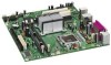
...the Chassis Fan Header 32 13. Connecting a 2 x 10 or 2 x 12 Power Supply Cable 33 14. Hi-Speed USB 2.0 Header Signal Names 31 6. Jumper Settings for Intel High Definition Audio 31 5. EMC Regulations 53 15. Intel Desktop Board DG945GCLF Components 10 2. Installing a DIMM 26 9. Safety Standards 45 12. Front Panel Audio Header Signal Names for the BIOS Setup Program Modes 35 8. BIOS Error Messages 44 11. BIOS Beep Codes 43 10. Location of the Standby Power Indicator 19 5. Desktop Boards DG945GCLF Components 11 3. BIOS Front-panel Power LED Blink Codes...
...the Chassis Fan Header 32 13. Connecting a 2 x 10 or 2 x 12 Power Supply Cable 33 14. Hi-Speed USB 2.0 Header Signal Names 31 6. Jumper Settings for Intel High Definition Audio 31 5. EMC Regulations 53 15. Intel Desktop Board DG945GCLF Components 10 2. Installing a DIMM 26 9. Safety Standards 45 12. Front Panel Audio Header Signal Names for the BIOS Setup Program Modes 35 8. BIOS Error Messages 44 11. BIOS Beep Codes 43 10. Location of the Standby Power Indicator 19 5. Desktop Boards DG945GCLF Components 11 3. BIOS Front-panel Power LED Blink Codes...
Product Guide
Page 9
... an onboard USB header • One IDE interface with ATA-100/66 support (two devices) • Two Serial ATA (3.0 Gb/s) interfaces • One VGA connector • One parallel port • One serial port • PS/2* keyboard and mouse ports • Intel® BIOS • Support for SMBIOS • Intel® Rapid BIOS Boot • Intel® Express BIOS Update • 10/100 Mb/s LAN Subsystem • Support for Advanced Configuration and Power Interface (ACPI) • Wake on USB, PCI, PS/2, LAN, and front panel...
... an onboard USB header • One IDE interface with ATA-100/66 support (two devices) • Two Serial ATA (3.0 Gb/s) interfaces • One VGA connector • One parallel port • One serial port • PS/2* keyboard and mouse ports • Intel® BIOS • Support for SMBIOS • Intel® Rapid BIOS Boot • Intel® Express BIOS Update • 10/100 Mb/s LAN Subsystem • Support for Advanced Configuration and Power Interface (ACPI) • Wake on USB, PCI, PS/2, LAN, and front panel...

Product Guide
Page 12
Intel Desktop Board DG945GCLF Product Guide Processor CAUTION Failure to use an appropriate power supply and/or not connecting the 12 V (2 x 2) power connector to the Desktop Board may result in damage to http://support.intel.com/support/motherboards/desktop/. 12 It supports: • 667/533 MHz unbuffered, non-registered DDR2 DIMMs • Serial Presence Detect (SPD) memory only • Non-ECC memory • Up to 2 GB of memory For the latest list of tested memory, go to...
Intel Desktop Board DG945GCLF Product Guide Processor CAUTION Failure to use an appropriate power supply and/or not connecting the 12 V (2 x 2) power connector to the Desktop Board may result in damage to http://support.intel.com/support/motherboards/desktop/. 12 It supports: • 667/533 MHz unbuffered, non-registered DDR2 DIMMs • Serial Presence Detect (SPD) memory only • Non-ECC memory • Up to 2 GB of memory For the latest list of tested memory, go to...

Product Guide
Page 13
... processor, memory, and the DMI interconnect. Onboard Audio Subsystem Desktop Board D945GCLF has a 4-channel (two independent 2-channel audio streams) onboard audio subsystem that are configurable through the audio device drivers: ― Line in/retasking jack ― Line out/retasking jack ― Mic in • Back panel audio connectors that includes a Realtek ALC662 audio codec. The audio subsystem features: • Intel High Definition Audio interface • Advanced jack sense, for the back panel connectors, that enables the audio...
... processor, memory, and the DMI interconnect. Onboard Audio Subsystem Desktop Board D945GCLF has a 4-channel (two independent 2-channel audio streams) onboard audio subsystem that are configurable through the audio device drivers: ― Line in/retasking jack ― Line out/retasking jack ― Mic in • Back panel audio connectors that includes a Realtek ALC662 audio codec. The audio subsystem features: • Intel High Definition Audio interface • Advanced jack sense, for the back panel connectors, that enables the audio...

Product Guide
Page 14
... Extended Capabilities Port (ECP) and Enhanced Parallel Port (EPP) support • Serial IRQ interface compatible with serialized IRQ support for PCI systems • PS/2-style mouse and keyboard interfaces • Intelligent power management, including a programmable wake up event interface • PCI power management support 14 Intel Desktop Board DG945GCLF Product Guide Figure 2 shows the default assignment of the back panel audio connectors. Poor audio quality occurs if passive (non-amplified) speakers are connected to this...
... Extended Capabilities Port (ECP) and Enhanced Parallel Port (EPP) support • Serial IRQ interface compatible with serialized IRQ support for PCI systems • PS/2-style mouse and keyboard interfaces • Intelligent power management, including a programmable wake up event interface • PCI power management support 14 Intel Desktop Board DG945GCLF Product Guide Figure 2 shows the default assignment of the back panel audio connectors. Poor audio quality occurs if passive (non-amplified) speakers are connected to this...
Product Guide
Page 16
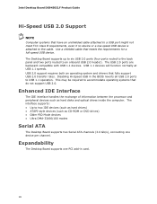
... Serial ATA channels (3.0 Gb/s), connecting one device per channel. The interface supports: • Up to USB 1.1 operation. Expandability The Desktop Board supports one PCI add-in the BIOS reverts all USB 2.0 ports to two IDE devices (such as hard drives) • ATAPI-style devices (such as hard disks and optical drives inside the computer. Disabling Hi-Speed USB in card. 16 This may be required to an onboard USB 2.0 header). USB 1.1 devices will function normally at USB 1.1 speeds. The USB 2.0 ports are backward compatible with USB 1.1 devices. The Desktop Board supports...
... Serial ATA channels (3.0 Gb/s), connecting one device per channel. The interface supports: • Up to USB 1.1 operation. Expandability The Desktop Board supports one PCI add-in the BIOS reverts all USB 2.0 ports to two IDE devices (such as hard drives) • ATAPI-style devices (such as hard disks and optical drives inside the computer. Disabling Hi-Speed USB in card. 16 This may be required to an onboard USB 2.0 header). USB 1.1 devices will function normally at USB 1.1 speeds. The USB 2.0 ports are backward compatible with USB 1.1 devices. The Desktop Board supports...

Product Guide
Page 17
... password to view and change all Setup options. For instructions on resetting the password, see Clearing Passwords on whether the supervisor or user password was entered. • Setting a user password restricts who can enter either the supervisor password or the user password to Setup. • If both passwords are set , you install a PCI add-in card in the BIOS Setup program. Desktop Board Features BIOS The BIOS provides the Power-On Self-Test (POST), the BIOS Setup program, the PCI and IDE auto-configuration utilities, and the video BIOS. The password prompt is displayed...
... password to view and change all Setup options. For instructions on resetting the password, see Clearing Passwords on whether the supervisor or user password was entered. • Setting a user password restricts who can enter either the supervisor password or the user password to Setup. • If both passwords are set , you install a PCI add-in card in the BIOS Setup program. Desktop Board Features BIOS The BIOS provides the Power-On Self-Test (POST), the BIOS Setup program, the PCI and IDE auto-configuration utilities, and the video BIOS. The password prompt is displayed...

Product Guide
Page 18
... for the location of the chassis fan header. 18 See Figure 12 on page 33 for the location of the power connectors. Hardware Support Power Connectors The Desktop Board has two power connectors. Intel Desktop Board DG945GCLF Product Guide Power Management Features Power management is implemented at several levels, including: • Advanced Configuration and Power Interface (ACPI) • Hardware support: ― Power connectors ― Fan headers ― +5 V standby power indicator LED ― LAN Wake capabilities ― Wake from USB ― Wake from PS/2 keyboard/mouse ―...
... for the location of the chassis fan header. 18 See Figure 12 on page 33 for the location of the power connectors. Hardware Support Power Connectors The Desktop Board has two power connectors. Intel Desktop Board DG945GCLF Product Guide Power Management Features Power management is implemented at several levels, including: • Advanced Configuration and Power Interface (ACPI) • Hardware support: ― Power connectors ― Fan headers ― +5 V standby power indicator LED ― LAN Wake capabilities ― Wake from USB ― Wake from PS/2 keyboard/mouse ―...
Product Guide
Page 21
...) can damage components. If such a station is off. Failure to disconnect power, telecommunications links, networks, or modems before performing any procedures can continue to : • Install the I/O shield • Install and remove the Desktop Board • Install and remove memory • Connect the IDE cable • Connect the SATA cable • Connect internal headers • Connect chassis fan and power supply cables • Set the BIOS configuration and audio jumpers • Clear passwords • Replace the battery Before You Begin CAUTIONS The procedures in this...
...) can damage components. If such a station is off. Failure to disconnect power, telecommunications links, networks, or modems before performing any procedures can continue to : • Install the I/O shield • Install and remove the Desktop Board • Install and remove memory • Connect the IDE cable • Connect the SATA cable • Connect internal headers • Connect chassis fan and power supply cables • Set the BIOS configuration and audio jumpers • Clear passwords • Replace the battery Before You Begin CAUTIONS The procedures in this...

Product Guide
Page 26
... end of the DIMM with the key in "Before You Begin" on the top edge of the DIMM into place. Turn off all peripheral devices connected to the open position. 5. Position the DIMM above the socket. Holding the DIMM by the edges, remove it from its anti-static package. 6. Intel Desktop Board DG945GCLF Product Guide 1. Insert the bottom edge of...
... end of the DIMM with the key in "Before You Begin" on the top edge of the DIMM into place. Turn off all peripheral devices connected to the open position. 5. Position the DIMM above the socket. Holding the DIMM by the edges, remove it from its anti-static package. 6. Intel Desktop Board DG945GCLF Product Guide 1. Insert the bottom edge of...
Product Guide
Page 27
... slowest drive. The cable supports the ATA-100 transfer protocol. Attach the cable end with drives using any parts you removed or disconnected to the computer. Turn off all peripheral devices connected to reach the DIMM sockets. 8. Reinstall and reconnect any other IDE transfer protocol are backward compatible with the single connector (blue) to an ATAPI CD-ROM drive. Do not connect an ATA device as a slave to the Intel Desktop Board...
... slowest drive. The cable supports the ATA-100 transfer protocol. Attach the cable end with drives using any parts you removed or disconnected to the computer. Turn off all peripheral devices connected to reach the DIMM sockets. 8. Reinstall and reconnect any other IDE transfer protocol are backward compatible with the single connector (blue) to an ATAPI CD-ROM drive. Do not connect an ATA device as a slave to the Intel Desktop Board...

Product Guide
Page 31
... and Replacing Desktop Board Components Front Panel HD Audio Header Figure 11, A shows the location of the USB 2.0 header. Front Panel Audio Header Signal Names for the headers. Turn off all peripheral devices connected to the computer. Hi-Speed USB 2.0 Header Signal Names USB Port A USB Port B Pin Signal Name 1 Power 3 D- 5 D+ 7 Ground 9 Key Pin Signal Name 2 Power 4 D- 6 D+ 8 Ground 10 No connect Note: USB ports may be assigned as needed. 31 Install a correctly keyed and shielded front panel audio cable. Table 5 shows the pin assignments for Intel High...
... and Replacing Desktop Board Components Front Panel HD Audio Header Figure 11, A shows the location of the USB 2.0 header. Front Panel Audio Header Signal Names for the headers. Turn off all peripheral devices connected to the computer. Hi-Speed USB 2.0 Header Signal Names USB Port A USB Port B Pin Signal Name 1 Power 3 D- 5 D+ 7 Ground 9 Key Pin Signal Name 2 Power 4 D- 6 D+ 8 Ground 10 No connect Note: USB ports may be assigned as needed. 31 Install a correctly keyed and shielded front panel audio cable. Table 5 shows the pin assignments for Intel High...

Product Guide
Page 34
BIOS Configuration Jumper Block The three-pin BIOS jumper block enables all board configuration to be done in unreliable computer operation. Figure 14 shows the location of the Desktop Board's BIOS configuration jumper block. Moving the jumper with the power on may result in the BIOS Setup program. Figure 14. Table 7 shows the jumper settings for the Setup program modes. 34 Intel Desktop Board DG945GCLF Product Guide Setting the BIOS Configuration Jumper NOTE Always turn off the power and unplug the power cord from the computer before changing a jumper.
BIOS Configuration Jumper Block The three-pin BIOS jumper block enables all board configuration to be done in unreliable computer operation. Figure 14 shows the location of the Desktop Board's BIOS configuration jumper block. Moving the jumper with the power on may result in the BIOS Setup program. Figure 14. Table 7 shows the jumper settings for the Setup program modes. 34 Intel Desktop Board DG945GCLF Product Guide Setting the BIOS Configuration Jumper NOTE Always turn off the power and unplug the power cord from the computer before changing a jumper.

Product Guide
Page 35
.... 2. Replace the cover, plug in "Before You Begin" on pins 2-3 as shown below. 6. Press and Setup displays a pop-up screen requesting that the board is installed in the event of the Desktop Board's BIOS configuration jumper block. Press to select Clear Passwords. Remove the computer cover. 4. Use the arrow keys to save the current values and exit Setup. 10. Configure (2-3) After the Power-On Self-Test (POST) runs, the BIOS displays the Maintenance Menu. Turn off...
.... 2. Replace the cover, plug in "Before You Begin" on pins 2-3 as shown below. 6. Press and Setup displays a pop-up screen requesting that the board is installed in the event of the Desktop Board's BIOS configuration jumper block. Press to select Clear Passwords. Remove the computer cover. 4. Use the arrow keys to save the current values and exit Setup. 10. Configure (2-3) After the Power-On Self-Test (POST) runs, the BIOS displays the Maintenance Menu. Turn off...

Product Guide
Page 41
... key after the Power-On Self-Test (POST) memory test begins and before the operating system boot begins. Updating the BIOS with the Intel Express BIOS Update utility: 1. To update the BIOS with the Intel® Express BIOS Update Utility With the Intel Express BIOS Update utility you need to a removable USB device. This runs the update program. 6. 3 Updating the BIOS The BIOS Setup program can be rebooted at the last Express BIOS Update window. 5. The Iflash BIOS update file is included in this file to update the BIOS. Download the file to your hard drive...
... key after the Power-On Self-Test (POST) memory test begins and before the operating system boot begins. Updating the BIOS with the Intel Express BIOS Update utility: 1. To update the BIOS with the Intel® Express BIOS Update Utility With the Intel Express BIOS Update utility you need to a removable USB device. This runs the update program. 6. 3 Updating the BIOS The BIOS Setup program can be rebooted at the last Express BIOS Update window. 5. The Iflash BIOS update file is included in this file to update the BIOS. Download the file to your hard drive...

Product Guide
Page 42
....EXE file from a bootable USB flash drive or other bootable USB media. 2. For more information about recovering the BIOS for desktop board DG945GCLF, go to the USB device. 3. The Iflash BIOS update files can update the system BIOS from the USB device and manually update the BIOS. CAUTION Do not interrupt the process or the system may not function properly. Configure the BIOS or use the F10 key option during POST to boot to : http://support.intel.com/support/motherboards/desktop/ 42...
....EXE file from a bootable USB flash drive or other bootable USB media. 2. For more information about recovering the BIOS for desktop board DG945GCLF, go to the USB device. 3. The Iflash BIOS update files can update the system BIOS from the USB device and manually update the BIOS. CAUTION Do not interrupt the process or the system may not function properly. Configure the BIOS or use the F10 key option during POST to boot to : http://support.intel.com/support/motherboards/desktop/ 42...

Product Guide
Page 43
... 0.5 second; BIOS Beep Codes Type Pattern Memory error Three long beeps Thermal warning Four alternating beeps: High tone, low tone, high tone, low tone Frequency 1280 Hz High tone: 2000 Hz Low tone: 1600 Hz 43 BIOS Front-panel Power LED Blink Codes Type Processor initialization complete POST complete BIOS update in Table 9. These beep codes can be heard through a speaker attached to display messages. A BIOS Error Messages BIOS Front-panel Power LED Blink Codes The front-panel power LED is used by the BIOS to the board's line out...
... 0.5 second; BIOS Beep Codes Type Pattern Memory error Three long beeps Thermal warning Four alternating beeps: High tone, low tone, high tone, low tone Frequency 1280 Hz High tone: 2000 Hz Low tone: 1600 Hz 43 BIOS Front-panel Power LED Blink Codes Type Processor initialization complete POST complete BIOS update in Table 9. These beep codes can be heard through a speaker attached to display messages. A BIOS Error Messages BIOS Front-panel Power LED Blink Codes The front-panel power LED is used by the BIOS to the board's line out...


