
Product Specification
Page 5
...11 1.2.3 Board Layout 12 1.2.4 Block Diagram 14 1.3 Online Support ...15 1.4 Processor ...15 1.5 System Memory ...16 1.5.1 Memory Configurations 17 1.6 Intel® 945G Chipset ...21 1.6.1 Intel 945G Graphics Subsystem 21 1.6.2 USB ...23 1.6.3 IDE Support 24 1.6.4 Real-Time Clock, CMOS SRAM, and Battery 25 1.7 PCI Express* Connectors 30 1.8 IEEE-1394a Connectors 30 1.9 Legacy I/O Controller 30 1.9.1 Serial Port...31 1.9.2 Parallel Port (Optional 31 1.9.3 Diskette Drive Controller 31 1.9.4 Keyboard and Mouse Interface 31 1.10 Audio Subsystem ...32 1.10.1 Audio Subsystem Software 32...
...11 1.2.3 Board Layout 12 1.2.4 Block Diagram 14 1.3 Online Support ...15 1.4 Processor ...15 1.5 System Memory ...16 1.5.1 Memory Configurations 17 1.6 Intel® 945G Chipset ...21 1.6.1 Intel 945G Graphics Subsystem 21 1.6.2 USB ...23 1.6.3 IDE Support 24 1.6.4 Real-Time Clock, CMOS SRAM, and Battery 25 1.7 PCI Express* Connectors 30 1.8 IEEE-1394a Connectors 30 1.9 Legacy I/O Controller 30 1.9.1 Serial Port...31 1.9.2 Parallel Port (Optional 31 1.9.3 Diskette Drive Controller 31 1.9.4 Keyboard and Mouse Interface 31 1.10 Audio Subsystem ...32 1.10.1 Audio Subsystem Software 32...

Product Specification
Page 7
... 14. LAN Connector LED Locations 34 12. Connection Diagram for Front Panel USB Connectors 61 19. Location of the Jumper Block 62 21. Power States and Targeted System Power 38 8. Supported Memory Configurations 16 5. DMA Channels ...47 vii Contents 3.8 Adjusting Boot Speed 84 3.8.1 Peripheral Selection and Configuration 84 3.8.2 BIOS Boot Optimizations 84 3.9 BIOS Security Features 85 4 Error Messages and Beep Codes 4.1 Speaker...87 4.2 BIOS Beep Codes...87 4.3 BIOS Error Messages 87 4.4 Port 80h POST Codes 88 Figures 1. Board Components ...12 2. Connection Diagram for...
... 14. LAN Connector LED Locations 34 12. Connection Diagram for Front Panel USB Connectors 61 19. Location of the Jumper Block 62 21. Power States and Targeted System Power 38 8. Supported Memory Configurations 16 5. DMA Channels ...47 vii Contents 3.8 Adjusting Boot Speed 84 3.8.1 Peripheral Selection and Configuration 84 3.8.2 BIOS Boot Optimizations 84 3.9 BIOS Security Features 85 4 Error Messages and Beep Codes 4.1 Speaker...87 4.2 BIOS Beep Codes...87 4.3 BIOS Error Messages 87 4.4 Port 80h POST Codes 88 Figures 1. Board Components ...12 2. Connection Diagram for...

Product Specification
Page 8
.... Beep Codes ...87 42. Port 80h POST Code Ranges 88 44. Intel Desktop Board D945GBO Technical Product Specification 11. Processor Core Power Connector 57 24. EMC Regulations ...77 36. BIOS Setup Configuration Jumper Settings 62 29. Environmental Specifications 71 33. Port 80h POST Codes 89 45. PCI Interrupt Routing Map 51 15. Front and Rear Chassis Fan Connectors 56 22. BIOS Error Messages 87 43. Chassis Intrusion Connector 56 19. PCI Configuration Space Map 49 13. Front Panel Connector 59 26. BIOS Setup Program Function Keys 80...
.... Beep Codes ...87 42. Port 80h POST Code Ranges 88 44. Intel Desktop Board D945GBO Technical Product Specification 11. Processor Core Power Connector 57 24. EMC Regulations ...77 36. BIOS Setup Configuration Jumper Settings 62 29. Environmental Specifications 71 33. Port 80h POST Codes 89 45. PCI Interrupt Routing Map 51 15. Front and Rear Chassis Fan Connectors 56 22. BIOS Error Messages 87 43. Chassis Intrusion Connector 56 19. PCI Configuration Space Map 49 13. Front Panel Connector 59 26. BIOS Setup Program Function Keys 80...
Product Specification
Page 10
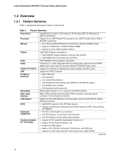
... : • Intel® 82945G Graphics Memory Controller Hub (GMCH) • Intel® 82801GH I/O Controller Hub (ICH7DH) Intel® GMA950 onboard graphics subsystem Audio 8-channel (7.1) audio subsystem with five analog audio outputs and one S/PDIF digital audio output (optical) using the Sigmatel* 9220/9223 audio codec Legacy I/O Control USB Peripheral Interfaces SATA RAID IEEE-1394a Interface LAN Support BIOS Legacy I/O controller for diskette drive, serial, parallel, and PS/2* ports Support for USB 2.0 devices • Eight USB ports • One serial port • Four Serial ATA...
... : • Intel® 82945G Graphics Memory Controller Hub (GMCH) • Intel® 82801GH I/O Controller Hub (ICH7DH) Intel® GMA950 onboard graphics subsystem Audio 8-channel (7.1) audio subsystem with five analog audio outputs and one S/PDIF digital audio output (optical) using the Sigmatel* 9220/9223 audio codec Legacy I/O Control USB Peripheral Interfaces SATA RAID IEEE-1394a Interface LAN Support BIOS Legacy I/O controller for diskette drive, serial, parallel, and PS/2* ports Support for USB 2.0 devices • Eight USB ports • One serial port • Four Serial ATA...

Product Specification
Page 14
... Slot 1 Gigabit Ethernet Controller LAN Connector USB Back Panel/Front Panel USB Ports Parallel ATA IDE Connector Parallel ATA IDE Interface LGA775 Processor Socket System Bus (1066/800 MHz) PCI Express x16 Interface PCI Express x16 Connector Intel 945G Chipset Intel 82945G Graphics and Memory Controller Hub (GMCH) Legacy I/O Controller LPC Bus Serial Port Parallel Port (Optional) PS/2 Mouse PS/2 Keyboard Diskette Drive Connector Intel 82801GH I/O Controller Hub (ICH7DH) Serial Peripheral Interface (SPI) Flash Device DMI Interconnect High Definition Audio Link VGA Port Channel...
... Slot 1 Gigabit Ethernet Controller LAN Connector USB Back Panel/Front Panel USB Ports Parallel ATA IDE Connector Parallel ATA IDE Interface LGA775 Processor Socket System Bus (1066/800 MHz) PCI Express x16 Interface PCI Express x16 Connector Intel 945G Chipset Intel 82945G Graphics and Memory Controller Hub (GMCH) Legacy I/O Controller LPC Bus Serial Port Parallel Port (Optional) PS/2 Mouse PS/2 Keyboard Diskette Drive Connector Intel 82801GH I/O Controller Hub (ICH7DH) Serial Peripheral Interface (SPI) Flash Device DMI Interconnect High Definition Audio Link VGA Port Channel...

Product Specification
Page 21
... provides interfaces to http://developer.intel.com/ Chapter 2 1.6.1 Intel 945G Graphics Subsystem The Intel 945G chipset contains two separate, mutually exclusive graphics options. The component also provides integrated graphics capabilities supporting 3D, 2D and display capabilities. The ICH7DH is used, or a PCI Express x16 add-in card is installed, the GMA950 graphics controller is disabled. 1.6.1.1 Intel® GMA950 Graphics Controller The Intel GMA950 graphics controller features the following devices: • Intel 82945G Graphics Memory Controller Hub (GMCH) with Direct...
... provides interfaces to http://developer.intel.com/ Chapter 2 1.6.1 Intel 945G Graphics Subsystem The Intel 945G chipset contains two separate, mutually exclusive graphics options. The component also provides integrated graphics capabilities supporting 3D, 2D and display capabilities. The ICH7DH is used, or a PCI Express x16 add-in card is installed, the GMA950 graphics controller is disabled. 1.6.1.1 Intel® GMA950 Graphics Controller The Intel GMA950 graphics controller features the following devices: • Intel 82945G Graphics Memory Controller Hub (GMCH) with Direct...

Product Specification
Page 22
... of this would be accessed by the graphics subsystem. When an ADD2/ADD2+ card is detected, the Intel GMA950 graphics controller is enabled and the PCI Express x16 connector is configured for DVO mode. DVO mode enables the DVO ports to be when using an ADD2/ADD2+ card • Dynamic Video Memory Technology (DVMT) support up to 224 MB • Intel® Zoom Utility For information about DVMT Obtaining graphics software and utilities Refer to Section...
... of this would be accessed by the graphics subsystem. When an ADD2/ADD2+ card is detected, the Intel GMA950 graphics controller is enabled and the PCI Express x16 connector is configured for DVO mode. DVO mode enables the DVO ports to be when using an ADD2/ADD2+ card • Dynamic Video Memory Technology (DVMT) support up to 224 MB • Intel® Zoom Utility For information about DVMT Obtaining graphics software and utilities Refer to Section...

Product Specification
Page 25
... use new low-voltage power connectors and require adaptors or power supplies equipped with data protection. The clock is devoted to ± 13 minutes/year at a block level across all mirrored sets. Replace the battery with an equivalent one logical drive. The ICH7DH allows for example, the date and time) might not be teamed together to be loaded into CMOS RAM at power-on separate disk drives. RAID...
... use new low-voltage power connectors and require adaptors or power supplies equipped with data protection. The clock is devoted to ± 13 minutes/year at a block level across all mirrored sets. Replace the battery with an equivalent one logical drive. The ICH7DH allows for example, the date and time) might not be teamed together to be loaded into CMOS RAM at power-on separate disk drives. RAID...
Product Specification
Page 40
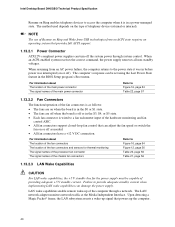
... Intel Desktop Board D945GBO Technical Product Specification Resume on Ring enables telephony devices to access the computer when it was in before power was interrupted (on or off). NOTE The use of providing adequate +5 V standby current. When an ACPI-enabled system receives the correct command, the power supply removes all non-standby voltages. The method used depends on the type of the hardware monitoring and fan control ASIC. • All fan connectors support...
... Intel Desktop Board D945GBO Technical Product Specification Resume on Ring enables telephony devices to access the computer when it was in before power was interrupted (on or off). NOTE The use of providing adequate +5 V standby current. When an ACPI-enabled system receives the correct command, the power supply removes all non-standby voltages. The method used depends on the type of the hardware monitoring and fan control ASIC. • All fan connectors support...

Product Specification
Page 46
... 0BFFFFH 0A0000H 09FFFFH 00000H Upper BIOS area (64 KB) Lower BIOS area (64 KB; 16 KB x 4) Add-in cards and BIOS settings. Intel Desktop Board D945GBO Technical Product Specification The amount of the system memory map. All installed system memory can be used will vary based on add-in Card BIOS and Buffer area (128 KB; 16 KB x 8) Standard PCI/ ISA Video Memory (SMM Memory) 128 KB DOS area...
... 0BFFFFH 0A0000H 09FFFFH 00000H Upper BIOS area (64 KB) Lower BIOS area (64 KB; 16 KB x 4) Add-in cards and BIOS settings. Intel Desktop Board D945GBO Technical Product Specification The amount of the system memory map. All installed system memory can be used will vary based on add-in Card BIOS and Buffer area (128 KB; 16 KB x 8) Standard PCI/ ISA Video Memory (SMM Memory) 128 KB DOS area...

Product Specification
Page 49
...00 Description Memory controller of Intel 82945G component PCI Express x16 graphics port (Note 1) Integrated graphics controller Intel High Definition Audio Controller PCI Express port 1 PCI Express port 2 PCI Express port 3 PCI Express port 4 USB UHCI controller 1 USB UHCI controller 2 USB UHCI controller 3 USB UHCI controller 4 EHCI controller PCI bridge PCI controller Parallel ATA IDE controller Serial ATA controller SMBus controller Gigabit LAN controller PCI Conventional bus connector 1 PCI Conventional bus connector 2 IEEE-1394a controller (if present) PCI Express video controller (Note...
...00 Description Memory controller of Intel 82945G component PCI Express x16 graphics port (Note 1) Integrated graphics controller Intel High Definition Audio Controller PCI Express port 1 PCI Express port 2 PCI Express port 3 PCI Express port 4 USB UHCI controller 1 USB UHCI controller 2 USB UHCI controller 3 USB UHCI controller 4 EHCI controller PCI bridge PCI controller Parallel ATA IDE controller Serial ATA controller SMBus controller Gigabit LAN controller PCI Conventional bus connector 1 PCI Conventional bus connector 2 IEEE-1394a controller (if present) PCI Express video controller (Note...

Product Specification
Page 52
... board's connectors. AC D JK L F H B E G I /O connectors (see page 54) 2.7.1 Back Panel Connectors Figure 15 shows the location of the back panel connectors. The other internal connectors are color-coded. The back panel connectors are not overcurrent protected and should connect only to devices inside the computer's chassis, such as fans and internal peripherals. Intel Desktop Board D945GBO Technical Product Specification 2.7 Connectors CAUTION Only the following connectors have overcurrent protection: back panel USB, front panel USB, and PS/2. Do not use...
... board's connectors. AC D JK L F H B E G I /O connectors (see page 54) 2.7.1 Back Panel Connectors Figure 15 shows the location of the back panel connectors. The other internal connectors are color-coded. The back panel connectors are not overcurrent protected and should connect only to devices inside the computer's chassis, such as fans and internal peripherals. Intel Desktop Board D945GBO Technical Product Specification 2.7 Connectors CAUTION Only the following connectors have overcurrent protection: back panel USB, front panel USB, and PS/2. Do not use...
Product Specification
Page 79
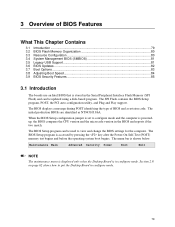
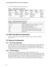
... ...79 3.2 BIOS Flash Memory Organization 80 3.3 Resource Configuration 80 3.4 System Management BIOS (SMBIOS 81 3.5 Legacy USB Support...81 3.6 BIOS Updates ...82 3.7 Boot Options ...83 3.8 Adjusting Boot Speed 84 3.9 BIOS Security Features 85 3.1 Introduction The boards use an Intel BIOS that is stored in the BIOS and reports if the two match. Maintenance Main Advanced Security Power Boot Exit NOTE The maintenance menu is displayed only when the Desktop Board is shown below. The menu bar is in configure mode. 79...
... ...79 3.2 BIOS Flash Memory Organization 80 3.3 Resource Configuration 80 3.4 System Management BIOS (SMBIOS 81 3.5 Legacy USB Support...81 3.6 BIOS Updates ...82 3.7 Boot Options ...83 3.8 Adjusting Boot Speed 84 3.9 BIOS Security Features 85 3.1 Introduction The boards use an Intel BIOS that is stored in the BIOS and reports if the two match. Maintenance Main Advanced Security Power Boot Exit NOTE The maintenance menu is displayed only when the Desktop Board is shown below. The menu bar is in configure mode. 79...
Product Specification
Page 80
... after adding a PCI card, the BIOS automatically configures interrupts, the I /O channel support. The IDE interface supports hard drives up the PCI IDE connector with independent I /O space, and other system resources. BIOS Setup Program Menu Bar Maintenance Main Advanced Security Clears passwords and displays processor information Displays processor and memory configuration Configures advanced features available through the chipset Sets passwords and security features Power Boot Configures power management features and power supply controls Selects boot options Exit Saves or...
... after adding a PCI card, the BIOS automatically configures interrupts, the I /O channel support. The IDE interface supports hard drives up the PCI IDE connector with independent I /O space, and other system resources. BIOS Setup Program Menu Bar Maintenance Main Advanced Security Clears passwords and displays processor information Displays processor and memory configuration Configures advanced features available through the chipset Sets passwords and security features Power Boot Configures power management features and power supply controls Selects boot options Exit Saves or...

Product Specification
Page 81
... information. Legacy USB support is a Desktop Management Interface (DMI) compliant method for system components. The BIOS enables applications such as an ATAPI master device. To use a USB keyboard to be used to access the BIOS Setup program, and to an ATAPI CD-ROM drive. 3.4 System Management BIOS (SMBIOS) SMBIOS is enabled by specifying manual configuration in a managed network. POST completes. 81 You can obtain the SMBIOS information. 3.5 Legacy USB Support Legacy USB support enables USB devices to enter and configure the BIOS Setup program and...
... information. Legacy USB support is a Desktop Management Interface (DMI) compliant method for system components. The BIOS enables applications such as an ATAPI master device. To use a USB keyboard to be used to access the BIOS Setup program, and to an ATAPI CD-ROM drive. 3.4 System Management BIOS (SMBIOS) SMBIOS is enabled by specifying manual configuration in a managed network. POST completes. 81 You can obtain the SMBIOS information. 3.5 Legacy USB Support Legacy USB support enables USB devices to enter and configure the BIOS Setup program and...
Product Specification
Page 83
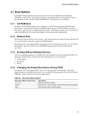
...-ROM drive, the system will attempt to boot from CD-ROM is listed as a boot device. This selection allows booting from a diskette drive, hard drives, CD-ROM, or the network. Table 39 lists the boot device menu options. Table 39. Overview of available boot devices (as set to Full. 3.7.3 Booting Without Attached Devices For use this key during POST, the User Access Level in the BIOS Setup program's Security menu must be set in the BIOS setup program's Boot Device Priority Submenu). This menu displays the list of BIOS Features 3.7 Boot Options...
...-ROM drive, the system will attempt to boot from CD-ROM is listed as a boot device. This selection allows booting from a diskette drive, hard drives, CD-ROM, or the network. Table 39 lists the boot device menu options. Table 39. Overview of available boot devices (as set to Full. 3.7.3 Booting Without Attached Devices For use this key during POST, the User Access Level in the BIOS Setup program's Security menu must be set in the BIOS setup program's Boot Device Priority Submenu). This menu displays the list of BIOS Features 3.7 Boot Options...

Product Specification
Page 84
... different monitors. Intel Desktop Board D945GBO Technical Product Specification 3.8 Adjusting Boot Speed These factors affect system boot speed: • Selecting and configuring peripherals properly • Optimized BIOS boot parameters 3.8.1 Peripheral Selection and Configuration The following techniques help improve system boot speed: • Choose a hard drive with parameters such as "power-up to four seconds of the following BIOS Setup program settings reduces the POST execution time: • In the Boot Menu, set the hard disk drive as logo displays, screen...
... different monitors. Intel Desktop Board D945GBO Technical Product Specification 3.8 Adjusting Boot Speed These factors affect system boot speed: • Selecting and configuring peripherals properly • Optimized BIOS boot parameters 3.8.1 Peripheral Selection and Configuration The following techniques help improve system boot speed: • Choose a hard drive with parameters such as "power-up to four seconds of the following BIOS Setup program settings reduces the POST execution time: • In the Boot Menu, set the hard disk drive as logo displays, screen...

Product Specification
Page 85
... BIOS Setup program. This is the user mode. • If only the supervisor password is booted. Passwords may be displayed before the computer is set, pressing the key at the password prompt of the BIOS Setup program allows the user restricted access to Setup. • If both passwords are set , users can enter either the supervisor password or the user password to access Setup. Table 40 shows the effects of options Can change all Setup options. Overview of BIOS Features 3.9 BIOS...
... BIOS Setup program. This is the user mode. • If only the supervisor password is booted. Passwords may be displayed before the computer is set, pressing the key at the password prompt of the BIOS Setup program allows the user restricted access to Setup. • If both passwords are set , users can enter either the supervisor password or the user password to access Setup. Table 40 shows the effects of options Can change all Setup options. Overview of BIOS Features 3.9 BIOS...

Product Specification
Page 88
... - 8F 90 - 9F A0 - DF E0 - FF: FF processor exception. Intel Desktop Board D945GBO Technical Product Specification 4.4 Port 80h POST Codes During the POST, the BIOS generates diagnostic progress codes (POST-codes) to I /O Busses: PCI, USB, ISA, ATA, etc. 5F is left at port 80h. Reserved for future use . Boot device selection. I /O port 80h. Start with PCI. F0 - E0 - The POST card can decode the port and display the contents on a medium such as a seven-segment...
... - 8F 90 - 9F A0 - DF E0 - FF: FF processor exception. Intel Desktop Board D945GBO Technical Product Specification 4.4 Port 80h POST Codes During the POST, the BIOS generates diagnostic progress codes (POST-codes) to I /O Busses: PCI, USB, ISA, ATA, etc. 5F is left at port 80h. Reserved for future use . Boot device selection. I /O port 80h. Start with PCI. F0 - E0 - The POST card can decode the port and display the contents on a medium such as a seven-segment...

Product Specification
Page 89
... the memory controller and the DIMMs Configuring memory Optimizing memory settings Initializing memory, such as ECC init Testing memory PCI Bus Enumerating PCI busses Allocating resources to PCI bus Hot Plug PCI controller initialization Reserved for PCI Bus USB Resetting USB bus Reserved for USB ATA/ATAPI/SATA Resetting PATA/SATA bus and all devices Reserved for ATA SMBus Resetting SMBUS Reserved for SMBUS Local Console Resetting the VGA controller Disabling the VGA controller Enabling the VGA controller Remote Console Resetting the console controller Disabling the console controller Enabling...
... the memory controller and the DIMMs Configuring memory Optimizing memory settings Initializing memory, such as ECC init Testing memory PCI Bus Enumerating PCI busses Allocating resources to PCI bus Hot Plug PCI controller initialization Reserved for PCI Bus USB Resetting USB bus Reserved for USB ATA/ATAPI/SATA Resetting PATA/SATA bus and all devices Reserved for ATA SMBus Resetting SMBUS Reserved for SMBUS Local Console Resetting the VGA controller Disabling the VGA controller Enabling the VGA controller Remote Console Resetting the console controller Disabling the console controller Enabling...


