
Product Guide
Page 3
... supported without further evaluation by Intel. Preface This Product Guide gives information about BIOS error messages and beep codes B Regulatory Compliance: safety standards, regulations, and product certifications iii The suitability of product features 2 Installing and Replacing Desktop Board Components: instructions on how to update the BIOS 4 Configuring for RAID (Intel® Matrix Storage Technology (Intel® MST)): information about configuring your system for RAID 5 Configuring for Intel® Rapid Recover Technology (Intel® RRT): information about configuring...
... supported without further evaluation by Intel. Preface This Product Guide gives information about BIOS error messages and beep codes B Regulatory Compliance: safety standards, regulations, and product certifications iii The suitability of product features 2 Installing and Replacing Desktop Board Components: instructions on how to update the BIOS 4 Configuring for RAID (Intel® Matrix Storage Technology (Intel® MST)): information about configuring your system for RAID 5 Configuring for Intel® Rapid Recover Technology (Intel® RRT): information about configuring...

Product Guide
Page 5
... Execution Technology (Intel® TXT 20 Hi-Speed USB 2.0 Support 21 Serial ATA...21 Serial ATA RAID 21 Intel® Rapid Recover Technology (Intel® RRT 22 Expandability...22 BIOS ...22 Serial ATA Auto Configuration 22 PCI and PCI Express* Auto Configuration 22 Security Passwords 23 Intel® Trusted Platform Module (Intel® TPM 23 Hardware Management Features 24 Fan Speed, Thermal, and Voltage Monitoring and Control 24 Chassis Intrusion 24 Power Management Features 25 ACPI ...25 Hardware Support 25 Power Connectors 25 Fan Headers 25 LAN Wake...
... Execution Technology (Intel® TXT 20 Hi-Speed USB 2.0 Support 21 Serial ATA...21 Serial ATA RAID 21 Intel® Rapid Recover Technology (Intel® RRT 22 Expandability...22 BIOS ...22 Serial ATA Auto Configuration 22 PCI and PCI Express* Auto Configuration 22 Security Passwords 23 Intel® Trusted Platform Module (Intel® TPM 23 Hardware Management Features 24 Fan Speed, Thermal, and Voltage Monitoring and Control 24 Chassis Intrusion 24 Power Management Features 25 ACPI ...25 Hardware Support 25 Power Connectors 25 Fan Headers 25 LAN Wake...

Product Guide
Page 6
...Card 44 Connecting Serial ATA (SATA) Cables 45 Connecting to Internal Headers 46 HD Audio Link Header 47 Front Panel Audio Header 47 Serial Port Header 48 Chassis Intrusion Header 48 Alternate Front Panel Power LED Header 48 Front Panel Header 49 USB 2.0 Headers 49 IEEE 1394a Header 50 Connecting to the Audio System 50 Connecting Chassis Fan and Power Supply Cables 51 Chassis Fan Cables 51 Power Supply Cables 52 Setting the BIOS Configuration Jumper 53 Clearing or Changing Passwords 54 Replacing the Battery 55 3 Updating the BIOS Updating the BIOS with the Intel® Express...
...Card 44 Connecting Serial ATA (SATA) Cables 45 Connecting to Internal Headers 46 HD Audio Link Header 47 Front Panel Audio Header 47 Serial Port Header 48 Chassis Intrusion Header 48 Alternate Front Panel Power LED Header 48 Front Panel Header 49 USB 2.0 Headers 49 IEEE 1394a Header 50 Connecting to the Audio System 50 Connecting Chassis Fan and Power Supply Cables 51 Chassis Fan Cables 51 Power Supply Cables 52 Setting the BIOS Configuration Jumper 53 Clearing or Changing Passwords 54 Replacing the Battery 55 3 Updating the BIOS Updating the BIOS with the Intel® Express...

Product Guide
Page 7
... Your RAID Set 65 Loading the Intel Matrix Storage Technology RAID Drivers and Software 66 Setting Up a "RAID Ready" System 66 5 Configuring for Intel® Rapid Recover Technology (Intel® RRT) Enabling Intel Rapid Recover Technology 67 Creating a Recovery Volume 68 Creating a Recovery Volume Using the RAID Option ROM 68 Creating a Recovery Volume Using the Intel Matrix Storage Console 68 Disk Synchronization Mode 69 Mounting the Recovery Disk 69 A Error Messages and Indicators BIOS Beep Codes 71 BIOS Error Messages 71 B Regulatory Compliance Safety Standards 73 Place Battery...
... Your RAID Set 65 Loading the Intel Matrix Storage Technology RAID Drivers and Software 66 Setting Up a "RAID Ready" System 66 5 Configuring for Intel® Rapid Recover Technology (Intel® RRT) Enabling Intel Rapid Recover Technology 67 Creating a Recovery Volume 68 Creating a Recovery Volume Using the RAID Option ROM 68 Creating a Recovery Volume Using the Intel Matrix Storage Console 68 Disk Synchronization Mode 69 Mounting the Recovery Disk 69 A Error Messages and Indicators BIOS Beep Codes 71 BIOS Error Messages 71 B Regulatory Compliance Safety Standards 73 Place Battery...

Product Guide
Page 8
... 7. Front Panel Audio Header Signal Names for the BIOS Setup Program Modes 54 16. Lead-Free Second Level Interconnect Marks 79 20. Intel Desktop Board DQ45CB Product Guide 16. Dual Channel Memory Configuration with Three DIMMs 39 17. Installing a PCI Express x16 Card 43 20. Internal Headers 46 23. Location of the Chassis Fan Headers 51 25. Alternate Front Panel Power LED Header Signal Names 48 12. Front Panel Header Signal Names 49 13. Installing a DIMM 41 19. Connecting Power Supply Cables 52 26. Serial Port Header Signal Names...
... 7. Front Panel Audio Header Signal Names for the BIOS Setup Program Modes 54 16. Lead-Free Second Level Interconnect Marks 79 20. Intel Desktop Board DQ45CB Product Guide 16. Dual Channel Memory Configuration with Three DIMMs 39 17. Installing a PCI Express x16 Card 43 20. Internal Headers 46 23. Location of the Chassis Fan Headers 51 25. Alternate Front Panel Power LED Header Signal Names 48 12. Front Panel Header Signal Names 49 13. Installing a DIMM 41 19. Connecting Power Supply Cables 52 26. Serial Port Header Signal Names...

Product Guide
Page 9
...Processor Main Memory Chipset Graphics Audio microATX (243.84 millimeters [9.60 inches] x 243.84 millimeters [9.60 inches]) Support for an Intel® processor in cards • Integrated graphics output via DVI-D and DVI-I ports Onboard subsystem, featuring: • Independent 6-channel (5.1) audio streams • 2-channel stereo audio streams via an onboard header • Intel® High Definition Audio (Intel® HD Audio) interface • Analog Devices AD1882 audio codec Expansion Capabilities Legacy I/O Support • One PCI Express 2.0 x16 connector • Two PCI Express...
...Processor Main Memory Chipset Graphics Audio microATX (243.84 millimeters [9.60 inches] x 243.84 millimeters [9.60 inches]) Support for an Intel® processor in cards • Integrated graphics output via DVI-D and DVI-I ports Onboard subsystem, featuring: • Independent 6-channel (5.1) audio streams • 2-channel stereo audio streams via an onboard header • Intel® High Definition Audio (Intel® HD Audio) interface • Analog Devices AD1882 audio codec Expansion Capabilities Legacy I/O Support • One PCI Express 2.0 x16 connector • Two PCI Express...

Product Guide
Page 10
... memory device • Support for SMBIOS • Intel® Rapid BIOS Boot • Intel® Express BIOS Update Power Management • Support for Advanced Configuration and Power Interface (ACPI) • Suspend to RAM (STR) • Wake on USB, PCI Express, PCI, LAN, and front panel • ENERGY STAR* capable Hardware Management LAN Support Hardware monitor with: • Three fan sensing inputs used to monitor fan activity • Intel® Quiet System Technology (Intel® QST) fan speed control • Voltage sensing to http://support.intel.com/support/motherboards...
... memory device • Support for SMBIOS • Intel® Rapid BIOS Boot • Intel® Express BIOS Update Power Management • Support for Advanced Configuration and Power Interface (ACPI) • Suspend to RAM (STR) • Wake on USB, PCI Express, PCI, LAN, and front panel • ENERGY STAR* capable Hardware Management LAN Support Hardware monitor with: • Three fan sensing inputs used to monitor fan activity • Intel® Quiet System Technology (Intel® QST) fan speed control • Voltage sensing to http://support.intel.com/support/motherboards...
Product Guide
Page 14
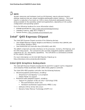
... about: • SDRAM specifications, http://intel.com/technology/memory/ • Installing memory, page 38 in a reduction of as much as PCI Express) require physical memory address locations that can reduce available addressable system memory. The ICH10DO is a centralized controller for MPEG-2 only ⎯ Software DVD at 30 fps full screen ⎯ Dynamic Video Memory Technology (DVMT) 5.0 14 Go to the following devices: • Intel 82Q45 Express Chipset Graphics and Memory Controller Hub (GMCH) with Direct...
... about: • SDRAM specifications, http://intel.com/technology/memory/ • Installing memory, page 38 in a reduction of as much as PCI Express) require physical memory address locations that can reduce available addressable system memory. The ICH10DO is a centralized controller for MPEG-2 only ⎯ Software DVD at 30 fps full screen ⎯ Dynamic Video Memory Technology (DVMT) 5.0 14 Go to the following devices: • Intel 82Q45 Express Chipset Graphics and Memory Controller Hub (GMCH) with Direct...

Product Guide
Page 21
... and mirroring • RAID 5 - NOTE Intel TXT requires the use of a processor with USB 1.1 devices. data striping • RAID 1 - Additionally, thirdparty software may be required. USB 1.1 devices will function normally at USB 1.1 speeds. data mirroring • RAID 0+1 (or RAID 10) - Disabling Hi-Speed USB in the BIOS reverts all USB 2.0 ports to three internal headers) via ICH10DO, connecting one device per channel. Serial ATA RAID ICH10DO supports Intel® Matrix Storage Technology which enables the following RAID (Redundant Array of software-based attacks.
... and mirroring • RAID 5 - NOTE Intel TXT requires the use of a processor with USB 1.1 devices. data striping • RAID 1 - Additionally, thirdparty software may be required. USB 1.1 devices will function normally at USB 1.1 speeds. data mirroring • RAID 0+1 (or RAID 10) - Disabling Hi-Speed USB in the BIOS reverts all USB 2.0 ports to three internal headers) via ICH10DO, connecting one device per channel. Serial ATA RAID ICH10DO supports Intel® Matrix Storage Technology which enables the following RAID (Redundant Array of software-based attacks.

Product Guide
Page 22
...hard drive should fail, either from the recovery drive. Expandability For system expansion, the Desktop Board provides the following the instructions in Chapter 3. The BIOS can override the auto-configuration options by following expansion slots: • One PCI Express 2.0 x16 connector (compatible with PCI Express 1.1 add-in cards) • Two PCI Express 1.1 x1 connectors • One PCI bus connector BIOS The BIOS provides the Power-On Self-Test (POST), the BIOS Setup program, the PCI/PCI Express auto-configuration utilities, and the video BIOS. You can be mounted as a hard drive...
...hard drive should fail, either from the recovery drive. Expandability For system expansion, the Desktop Board provides the following the instructions in Chapter 3. The BIOS can override the auto-configuration options by following expansion slots: • One PCI Express 2.0 x16 connector (compatible with PCI Express 1.1 add-in cards) • Two PCI Express 1.1 x1 connectors • One PCI bus connector BIOS The BIOS provides the Power-On Self-Test (POST), the BIOS Setup program, the PCI/PCI Express auto-configuration utilities, and the video BIOS. You can be mounted as a hard drive...

Product Guide
Page 25
... fans are off the computer power through the Advanced Configuration and Power Interface (ACPI) • Hardware support: ⎯ Power connectors ⎯ Fan headers ⎯ LAN wake capabilities ⎯ Instantly Available PC technology (Suspend to RAM) ⎯ +5 V standby power indicator LED ⎯ Wake from an AC power failure, the computer returns to thermal conditions. • All fan headers have a +12 V DC connection. The Desktop Board has a 4-pin processor fan header and two 3-pin chassis fan headers. 25 The computer's response can adjust the fan speed...
... fans are off the computer power through the Advanced Configuration and Power Interface (ACPI) • Hardware support: ⎯ Power connectors ⎯ Fan headers ⎯ LAN wake capabilities ⎯ Instantly Available PC technology (Suspend to RAM) ⎯ +5 V standby power indicator LED ⎯ Wake from an AC power failure, the computer returns to thermal conditions. • All fan headers have a +12 V DC connection. The Desktop Board has a 4-pin processor fan header and two 3-pin chassis fan headers. 25 The computer's response can adjust the fan speed...
Product Guide
Page 26
... Available (ACPI S3 sleep state) configuration. If the standby current necessary to provide adequate standby current when using this feature can be capable of delivering adequate +5 V standby current. The Desktop Board supports the PCI Bus Power Management Interface Specification. Failure to support multiple wake events from the PCI and/or USB buses exceeds power supply capacity, the Desktop Board may lose register settings stored in cards that powers up signal that support this Desktop Board must...
... Available (ACPI S3 sleep state) configuration. If the standby current necessary to provide adequate standby current when using this feature can be capable of delivering adequate +5 V standby current. The Desktop Board supports the PCI Bus Power Management Interface Specification. Failure to support multiple wake events from the PCI and/or USB buses exceeds power supply capacity, the Desktop Board may lose register settings stored in cards that powers up signal that support this Desktop Board must...

Product Guide
Page 29
... using and modifying electronic equipment. If such a station is off. 2 Installing and Replacing Desktop Board Components This chapter tells you how to: • Install the I/O shield • Install and remove the Desktop Board • Install and remove a processor • Install and remove memory • Install and remove a PCI Express x16 card • Connect the Serial ATA cables • Connect to the internal headers • Connect to the onboard audio system • Connect chassis fan and power supply cables • Set the BIOS configuration jumper • Clear passwords...
... using and modifying electronic equipment. If such a station is off. 2 Installing and Replacing Desktop Board Components This chapter tells you how to: • Install the I/O shield • Install and remove the Desktop Board • Install and remove a processor • Install and remove memory • Install and remove a PCI Express x16 card • Connect the Serial ATA cables • Connect to the internal headers • Connect to the onboard audio system • Connect chassis fan and power supply cables • Set the BIOS configuration jumper • Clear passwords...

Product Guide
Page 37
... Installing and Replacing Desktop Board Components Connecting the Processor Fan Heat Sink Cable Connect the processor fan heat sink cable to the processor installation manual. 37 However, since a fan with a 3-pin connector (Figure 13, B) can be used. however, a fan with a 3-pin connector cannot use the onboard fan control, the fan will always operate at full speed. Connecting the Processor Fan Heat Sink Cable Removing the Processor For instructions on how to remove the processor fan heat sink and processor, refer to the 4-pin processor fan header (see Figure 13). A fan with a 4-pin...
... Installing and Replacing Desktop Board Components Connecting the Processor Fan Heat Sink Cable Connect the processor fan heat sink cable to the processor installation manual. 37 However, since a fan with a 3-pin connector (Figure 13, B) can be used. however, a fan with a 3-pin connector cannot use the onboard fan control, the fan will always operate at full speed. Connecting the Processor Fan Heat Sink Cable Removing the Processor For instructions on how to remove the processor fan heat sink and processor, refer to the 4-pin processor fan header (see Figure 13). A fan with a 4-pin...

Product Guide
Page 50
... via audio software. Figure 23 shows the default back panel audio connector assignments. The audio connectors are connected to this output. 50 Item Description A Line In B Line Out C Mic In Figure 23. Intel Desktop Board DQ45CB Product Guide IEEE 1394a Header See Figure 22, H for the header. Back Panel Audio Connectors NOTE The back panel line out connector is designed to the Audio System After installing the Analog Devices audio driver from the Intel Express Installer DVD-ROM, the multi-channel audio...
... via audio software. Figure 23 shows the default back panel audio connector assignments. The audio connectors are connected to this output. 50 Item Description A Line In B Line Out C Mic In Figure 23. Intel Desktop Board DQ45CB Product Guide IEEE 1394a Header See Figure 22, H for the header. Back Panel Audio Connectors NOTE The back panel line out connector is designed to the Audio System After installing the Analog Devices audio driver from the Intel Express Installer DVD-ROM, the multi-channel audio...

Product Guide
Page 54
... the computer, turn on the computer, and allow it to clear passwords. Place the jumper on page 29. 2. Remove the computer cover. 4. Use the arrow keys to clear or change the BIOS security passwords (user and supervisor). Setup displays the Maintenance menu. 8. Replace the cover, plug in "Before You Begin" on pins 2-3 as shown below. 6. Press and Setup displays a pop-up screen requesting that the board is set to the computer. Use this menu to boot. 7.
... the computer, turn on the computer, and allow it to clear passwords. Place the jumper on page 29. 2. Remove the computer cover. 4. Use the arrow keys to clear or change the BIOS security passwords (user and supervisor). Setup displays the Maintenance menu. 8. Replace the cover, plug in "Before You Begin" on pins 2-3 as shown below. 6. Press and Setup displays a pop-up screen requesting that the board is set to the computer. Use this menu to boot. 7.

Product Guide
Page 55
...;C with an equivalent one. Replacing the Battery A coin-cell battery (CR2032) powers the real-time clock and CMOS memory. Please read the Intel TPM user guide and back-up Intel TPM keys and data before removing the battery. Batteries should be accurate. Turn off the computer. Press to maintain its monotonic counters. The clock is for anti-replay protection of used batteries must be in CMOS RAM (for example, the date...
...;C with an equivalent one. Replacing the Battery A coin-cell battery (CR2032) powers the real-time clock and CMOS memory. Please read the Intel TPM user guide and back-up Intel TPM keys and data before removing the battery. Batteries should be accurate. Turn off the computer. Press to maintain its monotonic counters. The clock is for anti-replay protection of used batteries must be in CMOS RAM (for example, the date...

Product Guide
Page 61
... included in the Windows environment. This runs the update program. 6. Click on your hard drive. (You can be rebooted at the last Express BIOS Update window. 5. This is useful if you can access the BIOS Setup program by either using the Intel Express BIOS Update utility or the Iflash Memory Update utility, and how to recover the BIOS if an update fails. 3 Updating the BIOS The BIOS Setup program can also save this file to a removable USB device. The BIOS file is required.
... included in the Windows environment. This runs the update program. 6. Click on your hard drive. (You can be rebooted at the last Express BIOS Update window. 5. This is useful if you can access the BIOS Setup program by either using the Intel Express BIOS Update utility or the Iflash Memory Update utility, and how to recover the BIOS if an update fails. 3 Updating the BIOS The BIOS Setup program can also save this file to a removable USB device. The BIOS file is required.

Product Guide
Page 66
... USB storage media). Setting Up a "RAID Ready" System The Intel Matrix Storage Technology Console software offers the flexibility to upgrade from http://support.intel.com/support/motherboards/desktop/ to the system. or If you can be using Microsoft Windows XP, press at http://support.intel.com/support/motherboards/desktop/. Select to install a third-party SCSI or RAID driver. Finish the Windows installation and install all necessary drivers. 4. Once additional SATA drives have a floppy drive, you will be using Microsoft Windows Vista, follow the setup installation...
... USB storage media). Setting Up a "RAID Ready" System The Intel Matrix Storage Technology Console software offers the flexibility to upgrade from http://support.intel.com/support/motherboards/desktop/ to the system. or If you can be using Microsoft Windows XP, press at http://support.intel.com/support/motherboards/desktop/. Select to install a third-party SCSI or RAID driver. Finish the Windows installation and install all necessary drivers. 4. Once additional SATA drives have a floppy drive, you will be using Microsoft Windows Vista, follow the setup installation...

Product Guide
Page 67
... If Configure SATA as , ensure it . You can be copied to enable it is reconnected. When using the Continuous Update policy, changes made to the data on request. For the setting Intel Rapid Recover Technology, select to the recovery drive continuously or on the master drive while the recovery drive is set to install the Intel Matrix Storage RAID driver during system POST. 2. To enable Intel Rapid Recover Technology, complete following steps: 1. Follow the instructions...
... If Configure SATA as , ensure it . You can be copied to enable it is reconnected. When using the Continuous Update policy, changes made to the data on request. For the setting Intel Rapid Recover Technology, select to the recovery drive continuously or on the master drive while the recovery drive is set to install the Intel Matrix Storage RAID driver during system POST. 2. To enable Intel Rapid Recover Technology, complete following steps: 1. Follow the instructions...


