Product Guide
Page 3
... product features 2 Installing and Replacing Desktop Board Components: instructions on how to install the Desktop Board and other hardware components 3 Updating the BIOS: instructions on how to update the BIOS A Error Messages and Indicators: information about BIOS error messages and beep codes B Regulatory Compliance: information about board layout, component installation, BIOS update, and regulatory requirements for Intended Applications All Intel Desktop Boards are arranged as medical, industrial, alarm systems, test equipment, etc. Use Only for Intel® Desktop Board DG41RQ.
... product features 2 Installing and Replacing Desktop Board Components: instructions on how to install the Desktop Board and other hardware components 3 Updating the BIOS: instructions on how to update the BIOS A Error Messages and Indicators: information about BIOS error messages and beep codes B Regulatory Compliance: information about board layout, component installation, BIOS update, and regulatory requirements for Intended Applications All Intel Desktop Boards are arranged as medical, industrial, alarm systems, test equipment, etc. Use Only for Intel® Desktop Board DG41RQ.
Product Guide
Page 5
...1 Desktop Board Features Desktop Board Components 11 Processor ...13 Main Memory...14 Intel® G41 Express Chipset 15 Audio Subsystem 16 Legacy Input/Output (I/O) Controller 17 LAN Subsystem 17 Hi-Speed USB 2.0 Support 18 Enhanced IDE Interface 18 Serial ATA...18 Expandability...19 BIOS ...19 Serial ATA and IDE Auto Configuration 19 PCI* and PCI Express* Auto Configuration 19 Security Passwords 20 Hardware Management Features 20 Hardware Monitoring and Fan Speed Control 20 Power Management Features 21 ACPI ...21 Hardware Support 21 Power Connectors 21 Fan Headers 21 LAN Wake...
...1 Desktop Board Features Desktop Board Components 11 Processor ...13 Main Memory...14 Intel® G41 Express Chipset 15 Audio Subsystem 16 Legacy Input/Output (I/O) Controller 17 LAN Subsystem 17 Hi-Speed USB 2.0 Support 18 Enhanced IDE Interface 18 Serial ATA...18 Expandability...19 BIOS ...19 Serial ATA and IDE Auto Configuration 19 PCI* and PCI Express* Auto Configuration 19 Security Passwords 20 Hardware Management Features 20 Hardware Monitoring and Fan Speed Control 20 Power Management Features 21 ACPI ...21 Hardware Support 21 Power Connectors 21 Fan Headers 21 LAN Wake...
Product Guide
Page 6
...x16 Card 39 Connecting the IDE Cable 40 Connecting the Serial ATA (SATA) Cables 41 Connecting to the Internal Headers and Connectors 42 Front Panel Audio Header 43 S/PDIF Connector 43 Serial Port Header 44 Parallel Port Header 44 Front Panel Header 45 Alternate Front Panel Power LED Header 45 USB 2.0 Headers 46 Connecting to the Back Panel Audio Connectors 47 Connecting Chassis Fan and Power Supply Cables 48 Connecting a Chassis Fan Cable 48 Connecting Supply Power Cables 49 Setting the BIOS Configuration Jumper 50 Clearing Passwords 51 Replacing the Battery 52 3 Updating the...
...x16 Card 39 Connecting the IDE Cable 40 Connecting the Serial ATA (SATA) Cables 41 Connecting to the Internal Headers and Connectors 42 Front Panel Audio Header 43 S/PDIF Connector 43 Serial Port Header 44 Parallel Port Header 44 Front Panel Header 45 Alternate Front Panel Power LED Header 45 USB 2.0 Headers 46 Connecting to the Back Panel Audio Connectors 47 Connecting Chassis Fan and Power Supply Cables 48 Connecting a Chassis Fan Cable 48 Connecting Supply Power Cables 49 Setting the BIOS Configuration Jumper 50 Clearing Passwords 51 Replacing the Battery 52 3 Updating the...
Product Guide
Page 7
.... Beep Codes 61 15. Connecting Power Supply Cables 49 24. Location of the Rear Chassis Fan Header 48 23. Close the Load Plate 32 12. Installing a DIMM 36 16. Front Panel Audio Header Signal Names for the BIOS Setup Program Modes 50 14. Serial Port Header Signal Names 44 9. Installing a PCI Express x16 Card 38 17. Connecting a Serial ATA Cable 41 20. USB 2.0 Header Signal Names 46 13. BIOS Error Messages 61 16. Lift the Load Plate 30 8. Intel Desktop Board DG41RQ Components 12 3. LAN Connector LEDs 18 5. Jumper Settings for...
.... Beep Codes 61 15. Connecting Power Supply Cables 49 24. Location of the Rear Chassis Fan Header 48 23. Close the Load Plate 32 12. Installing a DIMM 36 16. Front Panel Audio Header Signal Names for the BIOS Setup Program Modes 50 14. Serial Port Header Signal Names 44 9. Installing a PCI Express x16 Card 38 17. Connecting a Serial ATA Cable 41 20. USB 2.0 Header Signal Names 46 13. BIOS Error Messages 61 16. Lift the Load Plate 30 8. Intel Desktop Board DG41RQ Components 12 3. LAN Connector LEDs 18 5. Jumper Settings for...

Product Guide
Page 9
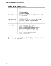
... PCI Express x1 connector • Two PCI* bus connectors • Up to eight USB 2.0 ports: ― Four ports routed to the back panel ― Four ports routed to two USB headers • Four Serial ATA (SATA) channels (3.0 Gb/s) via the ICH7 • One IDE interface with ATA-66/100 support (two devices) • One VGA connector • One parallel port header • One serial port header • PS/2* keyboard and mouse connectors continued 9 Feature Summary Form Factor Processor Main Memory Chipset Graphics Audio LAN Support Expansion...
... PCI Express x1 connector • Two PCI* bus connectors • Up to eight USB 2.0 ports: ― Four ports routed to the back panel ― Four ports routed to two USB headers • Four Serial ATA (SATA) channels (3.0 Gb/s) via the ICH7 • One IDE interface with ATA-66/100 support (two devices) • One VGA connector • One parallel port header • One serial port header • PS/2* keyboard and mouse connectors continued 9 Feature Summary Form Factor Processor Main Memory Chipset Graphics Audio LAN Support Expansion...
Product Guide
Page 10
...; Intel® Rapid BIOS Boot • Intel® Express BIOS Update Power Management • Support for Advanced Configuration and Power Interface (ACPI) • Suspend to RAM (STR) • Wake on USB, PCI Express, LAN, PS/2, and front panel • ENERGY STAR* capable Hardware Monitor • Voltage sense to detect out of range power supply voltages • Thermal sense to detect out of range temperatures • Two fan headers • Two fan sense inputs to monitor fan speed Supported Operating Systems The Desktop Board supports the...
...; Intel® Rapid BIOS Boot • Intel® Express BIOS Update Power Management • Support for Advanced Configuration and Power Interface (ACPI) • Suspend to RAM (STR) • Wake on USB, PCI Express, LAN, PS/2, and front panel • ENERGY STAR* capable Hardware Monitor • Voltage sense to detect out of range power supply voltages • Thermal sense to detect out of range temperatures • Two fan headers • Two fan sense inputs to monitor fan speed Supported Operating Systems The Desktop Board supports the...

Product Guide
Page 12
...V processor core voltage connector (2 x 2 pin) Processor socket Processor fan header (4-pin) DDR2 Channel A DIMM 0 socket DDR2 Channel B DIMM 0 socket Main power connector (2 x 12 pin) IDE connector Battery Alternate front panel power LED header Front panel header Serial ATA connectors (4) BIOS configuration jumper block High-speed USB 2.0 headers (2) Speaker Serial port header S/PDIF connector Front panel audio header Go to the following links for more information about: • Intel Desktop Board DG41RQ • Supported processors • Audio software and utilities • LAN software...
...V processor core voltage connector (2 x 2 pin) Processor socket Processor fan header (4-pin) DDR2 Channel A DIMM 0 socket DDR2 Channel B DIMM 0 socket Main power connector (2 x 12 pin) IDE connector Battery Alternate front panel power LED header Front panel header Serial ATA connectors (4) BIOS configuration jumper block High-speed USB 2.0 headers (2) Speaker Serial port header S/PDIF connector Front panel audio header Go to the following links for more information about: • Intel Desktop Board DG41RQ • Supported processors • Audio software and utilities • LAN software...
Product Guide
Page 16
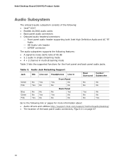
Intel Desktop Board DG41RQ Product Guide Audio Subsystem The onboard audio subsystem consists of the following: • Intel® ICH7 • Realtek ALC662 audio codec • Back panel audio connectors • Onboard audio headers/connectors: ⎯ Front panel audio header supporting both Intel High Definition Audio and AC '97 Audio ⎯ HD Audio Link header ⎯ S/PDIF connector The audio subsystem supports the following features: • A signal-to the following link or pages for the front panel and back panel audio jacks. Table...
Intel Desktop Board DG41RQ Product Guide Audio Subsystem The onboard audio subsystem consists of the following: • Intel® ICH7 • Realtek ALC662 audio codec • Back panel audio connectors • Onboard audio headers/connectors: ⎯ Front panel audio header supporting both Intel High Definition Audio and AC '97 Audio ⎯ HD Audio Link header ⎯ S/PDIF connector The audio subsystem supports the following features: • A signal-to the following link or pages for the front panel and back panel audio jacks. Table...

Product Guide
Page 17
... LEDs indicate the status of the LAN. Figure 2. LAN Connector LEDs 17 Desktop Board Features Legacy Input/Output (I/O) Controller The Winbond 83627DHG-P legacy I/O controller provides the following functions: • One serial port interface via an onboard header • One parallel port interface via an onboard header • Serial IRQ interface compatible with serialized IRQ support for PCI systems • Intelligent power management, including a programmable wake up event interface • PCI power management support LAN Subsystem The LAN subsystem includes: • Intel...
... LEDs indicate the status of the LAN. Figure 2. LAN Connector LEDs 17 Desktop Board Features Legacy Input/Output (I/O) Controller The Winbond 83627DHG-P legacy I/O controller provides the following functions: • One serial port interface via an onboard header • One parallel port interface via an onboard header • Serial IRQ interface compatible with serialized IRQ support for PCI systems • Intelligent power management, including a programmable wake up event interface • PCI power management support LAN Subsystem The LAN subsystem includes: • Intel...
Product Guide
Page 18
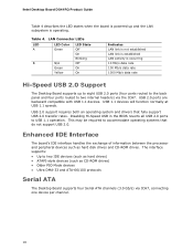
... Hi-Speed USB 2.0 Support The Desktop Board supports up and the LAN subsystem is powered up to eight USB 2.0 ports (four ports routed to the back panel and four ports routed to two IDE devices (such as hard drives) • ATAPI-style devices (such as hard disk drives and CD-ROM drives. USB 2.0 ports are backward compatible with USB 1.1 devices. Table 4. Enhanced IDE Interface The board's IDE interface handles the exchange of information between the processor and peripheral devices such as CD-ROM drives) •...
... Hi-Speed USB 2.0 Support The Desktop Board supports up and the LAN subsystem is powered up to eight USB 2.0 ports (four ports routed to the back panel and four ports routed to two IDE devices (such as hard drives) • ATAPI-style devices (such as hard disk drives and CD-ROM drives. USB 2.0 ports are backward compatible with USB 1.1 devices. Table 4. Enhanced IDE Interface The board's IDE interface handles the exchange of information between the processor and peripheral devices such as CD-ROM drives) •...
Product Guide
Page 19
... IDE device (such as a hard drive) in your computer, the auto-configuration utility in the BIOS automatically detects and configures the device for your computer, the PCI/PCI Express auto-configuration utility in the BIOS automatically detects and configures the resources (IRQs, DMA channels, and I/O space) for that add-in the BIOS Setup program. You can be updated by specifying manual configuration in card. Serial ATA and IDE Auto Configuration If you install a PCI/PCI Express add-in the Serial Peripheral Interface (SPI) Flash component. Desktop Board...
... IDE device (such as a hard drive) in your computer, the auto-configuration utility in the BIOS automatically detects and configures the device for your computer, the PCI/PCI Express auto-configuration utility in the BIOS automatically detects and configures the resources (IRQs, DMA channels, and I/O space) for that add-in the BIOS Setup program. You can be updated by specifying manual configuration in card. Serial ATA and IDE Auto Configuration If you install a PCI/PCI Express add-in the Serial Peripheral Interface (SPI) Flash component. Desktop Board...
Product Guide
Page 20
... (processor and a remote thermal sensor) 20 Fan speed controllers and sensors are then available for Management (WfM) specification. Setup options are integrated into the legacy I /O controller, delivering acoustically- Related Links: For instructions on resetting the password, see Clearing Passwords on whether the supervisor or user password was entered. • Setting a user password restricts who can boot the computer. If only the supervisor password is set, pressing at the password prompt of Intel Desktop Board DG41RQ enable the board to...
... (processor and a remote thermal sensor) 20 Fan speed controllers and sensors are then available for Management (WfM) specification. Setup options are integrated into the legacy I /O controller, delivering acoustically- Related Links: For instructions on resetting the password, see Clearing Passwords on whether the supervisor or user password was entered. • Setting a user password restricts who can boot the computer. If only the supervisor password is set, pressing at the password prompt of Intel Desktop Board DG41RQ enable the board to...
Product Guide
Page 21
... location of ACPI with the Desktop Board requires an operating system that provides full ACPI support. When an ACPI-enabled computer receives the correct command, the power supply removes all non-standby voltages. The computer's response can turn off the computer power through the Advanced Configuration and Power Interface (ACPI) • Hardware support: ⎯ Power connectors ⎯ Fan headers ⎯ LAN wake capabilities ⎯ Instantly Available PC technology (Suspend to RAM) ⎯ +5 V standby power indicator LED ⎯ Wake from USB...
... location of ACPI with the Desktop Board requires an operating system that provides full ACPI support. When an ACPI-enabled computer receives the correct command, the power supply removes all non-standby voltages. The computer's response can turn off the computer power through the Advanced Configuration and Power Interface (ACPI) • Hardware support: ⎯ Power connectors ⎯ Fan headers ⎯ LAN wake capabilities ⎯ Instantly Available PC technology (Suspend to RAM) ⎯ +5 V standby power indicator LED ⎯ Wake from USB...
Product Guide
Page 22
.... Intel Desktop Board DG41RQ Product Guide • All fan headers support closed-loop fan control that can damage the power supply and/or effect ACPI S3 sleep state functionality. LAN wakeup capabilities enable remote wake-up the computer. While in power management and can damage the power supply. The Desktop Board supports the PCI Bus Power Management Interface Specification. When signaled by the LED turning amber. If the standby current necessary to enter the ACPI S3 (Suspend-toRAM) sleep state. Failure to...
.... Intel Desktop Board DG41RQ Product Guide • All fan headers support closed-loop fan control that can damage the power supply and/or effect ACPI S3 sleep state functionality. LAN wakeup capabilities enable remote wake-up the computer. While in power management and can damage the power supply. The Desktop Board supports the PCI Bus Power Management Interface Specification. When signaled by the LED turning amber. If the standby current necessary to enter the ACPI S3 (Suspend-toRAM) sleep state. Failure to...
Product Guide
Page 25
... to operate even though the front panel power button is not available, you how to: • Install the I/O shield • Install and remove the Desktop Board • Install and remove a processor • Install and remove memory • Install and remove a PCI Express x16 card • Connect the IDE and Serial ATA cables • Connect to the internal headers and connectors • Connect to the audio system • Connect chassis fan and power supply cables • Set the BIOS configuration jumper • Clear passwords • Replace the battery Before You Begin CAUTION The...
... to operate even though the front panel power button is not available, you how to: • Install the I/O shield • Install and remove the Desktop Board • Install and remove a processor • Install and remove memory • Install and remove a PCI Express x16 card • Connect the IDE and Serial ATA cables • Connect to the internal headers and connectors • Connect to the audio system • Connect chassis fan and power supply cables • Set the BIOS configuration jumper • Clear passwords • Replace the battery Before You Begin CAUTION The...
Product Guide
Page 48
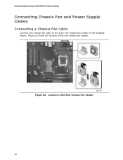
Intel Desktop Board DG41RQ Product Guide Connecting Chassis Fan and Power Supply Cables Connecting a Chassis Fan Cable Connect your chassis fan cable to the 3-pin rear chassis fan header on the Desktop Board. Location of the rear chassis fan header. Figure 22. Figure 22 shows the location of the Rear Chassis Fan Header 48
Intel Desktop Board DG41RQ Product Guide Connecting Chassis Fan and Power Supply Cables Connecting a Chassis Fan Cable Connect your chassis fan cable to the 3-pin rear chassis fan header on the Desktop Board. Location of the rear chassis fan header. Figure 22. Figure 22 shows the location of the Rear Chassis Fan Header 48
Product Guide
Page 50
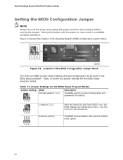
...the BIOS Configuration Jumper Block The three-pin BIOS jumper block enables all board configurations to clear passwords. Table 13. Figure 24 shows the location of the Desktop Board's BIOS configuration jumper block. Jumper Settings for the BIOS Setup Program Modes Jumper Setting Mode Normal (default) (1-2) Description The BIOS uses the current configuration and passwords for the BIOS Setup program modes. Moving the jumper with the power on may result in the BIOS Setup program. Intel Desktop Board DG41RQ Product Guide Setting the BIOS Configuration Jumper NOTE Always turn off...
...the BIOS Configuration Jumper Block The three-pin BIOS jumper block enables all board configurations to clear passwords. Table 13. Figure 24 shows the location of the Desktop Board's BIOS configuration jumper block. Jumper Settings for the BIOS Setup Program Modes Jumper Setting Mode Normal (default) (1-2) Description The BIOS uses the current configuration and passwords for the BIOS Setup program modes. Moving the jumper with the power on may result in the BIOS Setup program. Intel Desktop Board DG41RQ Product Guide Setting the BIOS Configuration Jumper NOTE Always turn off...
Product Guide
Page 51
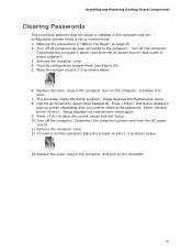
... Replace the cover, plug in the computer, turn on pins 1-2 as shown below . 13. Turn off all peripheral devices connected to normal mode. 1. Setup displays the maintenance menu again. 9. Observe the precautions in the computer and the configuration jumper block is installed in "Before You Begin" on pins 2-3 as shown below . 6. Turn off the computer. Remove the computer cover. 4. Press and Setup displays a pop-up screen requesting that the board is set...
... Replace the cover, plug in the computer, turn on pins 1-2 as shown below . 13. Turn off all peripheral devices connected to normal mode. 1. Setup displays the maintenance menu again. 9. Observe the precautions in the computer and the configuration jumper block is installed in "Before You Begin" on pins 2-3 as shown below . 6. Turn off the computer. Remove the computer cover. 4. Press and Setup displays a pop-up screen requesting that the board is set...

Product Guide
Page 57
...://support.intel.com/support/motherboards/desktop/ 2. 3 Updating the BIOS The BIOS Setup program can be rebooted at the last Express BIOS Update window. 5. Download the file to your hard drive where it was saved. This is required. Double-click the executable file from the location on your hard drive. (You can update the system BIOS while in an automated update utility that combines the functionality of the Intel® Flash Memory Update Utility and the ease of use of Windows-based installation wizards...
...://support.intel.com/support/motherboards/desktop/ 2. 3 Updating the BIOS The BIOS Setup program can be rebooted at the last Express BIOS Update window. 5. Download the file to your hard drive where it was saved. This is required. Double-click the executable file from the location on your hard drive. (You can update the system BIOS while in an automated update utility that combines the functionality of the Intel® Flash Memory Update Utility and the ease of use of Windows-based installation wizards...

Product Guide
Page 60
... USB device. 3. Manually run the IFLASH.EXE file from a BIOS update failure, go to a bootable USB flash drive or other bootable USB media. 2. Uncompress the BIOS update file and copy the .BIO file, IFLASH.EXE, and .ITK file (optional) to : http://support.intel.com/support/motherboards/desktop/sb/CS-022312.htm 60 Configure the BIOS or use the F10 option during POST to boot to BIOS size and recovery requirements, a CD-R with the .BIO file in the root directory will interrupt the BIOS update; Intel Desktop Board DG41RQ Product Guide...
... USB device. 3. Manually run the IFLASH.EXE file from a BIOS update failure, go to a bootable USB flash drive or other bootable USB media. 2. Uncompress the BIOS update file and copy the .BIO file, IFLASH.EXE, and .ITK file (optional) to : http://support.intel.com/support/motherboards/desktop/sb/CS-022312.htm 60 Configure the BIOS or use the F10 option during POST to boot to BIOS size and recovery requirements, a CD-R with the .BIO file in the root directory will interrupt the BIOS update; Intel Desktop Board DG41RQ Product Guide...


