Product Specification
Page 5
... Online Support 15 1.4 Processor 15 1.5 System Memory 16 1.5.1 Memory Configurations 17 1.6 Intel® G33 Express Chipset 19 1.6.1 Intel G33 Graphics Subsystem 19 1.6.2 Intel® Viiv™ Processor Technology 21 1.6.3 USB 21 1.6.4 Serial ATA Interfaces 21 1.7 Parallel IDE Controller 22 1.8 Real-Time Clock Subsystem 23 1.9 Legacy I/O Controller 23 1.9.1 Serial Port Interface 23 1.9.2 Diskette Drive Interface 23 1.9.3 PS/2 Keyboard and Mouse Interface 24 1.10 Audio Subsystem 24 1.10.1 Audio Subsystem Software 25 1.10.2 Audio Connectors and Headers 25 1.11 LAN Subsystem...
... Online Support 15 1.4 Processor 15 1.5 System Memory 16 1.5.1 Memory Configurations 17 1.6 Intel® G33 Express Chipset 19 1.6.1 Intel G33 Graphics Subsystem 19 1.6.2 Intel® Viiv™ Processor Technology 21 1.6.3 USB 21 1.6.4 Serial ATA Interfaces 21 1.7 Parallel IDE Controller 22 1.8 Real-Time Clock Subsystem 23 1.9 Legacy I/O Controller 23 1.9.1 Serial Port Interface 23 1.9.2 Diskette Drive Interface 23 1.9.3 PS/2 Keyboard and Mouse Interface 24 1.10 Audio Subsystem 24 1.10.1 Audio Subsystem Software 25 1.10.2 Audio Connectors and Headers 25 1.11 LAN Subsystem...
Product Specification
Page 6
...58 3.3.2 PCI IDE Support 59 3.4 System Management BIOS (SMBIOS 59 3.5 Legacy USB Support 60 3.6 BIOS Updates 61 3.6.1 Language Support 61 3.6.2 Custom Splash Screen 62 3.7 BIOS Recovery 62 3.8 Boot Options 63 3.8.1 CD-ROM Boot 63 3.8.2 Network Boot 63 3.8.3 Booting Without Attached Devices 63 3.8.4 Changing the Default Boot Device During POST 63 3.9 Adjusting Boot Speed 64 3.9.1 Peripheral Selection and Configuration 64 3.9.2 BIOS Boot Optimizations 64 3.10 BIOS Security Features 65 4 Error Messages and Beep Codes 4.1 Speaker 67 4.2 BIOS Beep Codes 67 4.3 BIOS Error Messages...
...58 3.3.2 PCI IDE Support 59 3.4 System Management BIOS (SMBIOS 59 3.5 Legacy USB Support 60 3.6 BIOS Updates 61 3.6.1 Language Support 61 3.6.2 Custom Splash Screen 62 3.7 BIOS Recovery 62 3.8 Boot Options 63 3.8.1 CD-ROM Boot 63 3.8.2 Network Boot 63 3.8.3 Booting Without Attached Devices 63 3.8.4 Changing the Default Boot Device During POST 63 3.9 Adjusting Boot Speed 64 3.9.1 Peripheral Selection and Configuration 64 3.9.2 BIOS Boot Optimizations 64 3.10 BIOS Security Features 65 4 Error Messages and Beep Codes 4.1 Speaker 67 4.2 BIOS Beep Codes 67 4.3 BIOS Error Messages...
Product Specification
Page 7
... Header 44 14. Main Power Connector 46 20. Memory Channel Configuration and DIMM Configuration 18 4. Location of the Jumper Block 50 14. Connection Diagram for Front Panel USB Headers 49 13. LAN Connector LED States 27 6. Chassis Intrusion Header 44 13. Major Board Components 12 2. Thermal Sensors and Fan Headers 29 7. Component-side Connectors and Headers 42 11. Connection Diagram for Front Panel Header 47 12. Feature Summary 10 2. Audio Jack Support 24 5. Serial ATA Connectors 44 12. Front and Rear Chassis Fan Headers 44 15. Processor Core Power...
... Header 44 14. Main Power Connector 46 20. Memory Channel Configuration and DIMM Configuration 18 4. Location of the Jumper Block 50 14. Connection Diagram for Front Panel USB Headers 49 13. LAN Connector LED States 27 6. Chassis Intrusion Header 44 13. Major Board Components 12 2. Thermal Sensors and Fan Headers 29 7. Component-side Connectors and Headers 42 11. Connection Diagram for Front Panel Header 47 12. Feature Summary 10 2. Audio Jack Support 24 5. Serial ATA Connectors 44 12. Front and Rear Chassis Fan Headers 44 15. Processor Core Power...
Product Specification
Page 8
... Front Panel Power LED Header 48 24. Thermal Considerations for BIOS Recovery 62 32. BIOS Setup Program Menu Bar 58 30. Acceptable Drives/Media Types for Components 55 28. Beep Codes 67 35. Port 80h POST Code Ranges 68 37. Port 80h POST Codes 69 38. Desktop Board DG33BU Environmental Specifications 56 29. BIOS Setup Program Function Keys 58 31. States for a One-Color Power LED 48 22. Fan Header Current Capability 53 27. Boot Device Menu Options 63 33. Lead-Free Board Markings 78...
... Front Panel Power LED Header 48 24. Thermal Considerations for BIOS Recovery 62 32. BIOS Setup Program Menu Bar 58 30. Acceptable Drives/Media Types for Components 55 28. Beep Codes 67 35. Port 80h POST Code Ranges 68 37. Port 80h POST Codes 69 38. Desktop Board DG33BU Environmental Specifications 56 29. BIOS Setup Program Function Keys 58 31. States for a One-Color Power LED 48 22. Fan Header Current Capability 53 27. Boot Device Menu Options 63 33. Lead-Free Board Markings 78...
Product Specification
Page 10
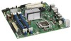
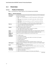
...Board DG33BU Technical Product Specification 1.1 Overview 1.1.1 Feature Summary Table 1 summarizes the major features of : • Intel® 82G33 Graphics and Memory Controller Hub (GMCH) • Intel® 82801IH I/O Controller Hub (ICH9DH) Intel® Graphics Media Accelerator (Intel® GMA) 3100 onboard graphics subsystem Audio 6-channel (5.1) audio subsystem using the Realtek* ALC888 audio codec Legacy I/O Control Peripheral Interfaces LAN Support BIOS Instantly Available PC Technology Legacy I/O controller for diskette drive, serial, and PS/2* ports • 12 USB 2.0 ports...
...Board DG33BU Technical Product Specification 1.1 Overview 1.1.1 Feature Summary Table 1 summarizes the major features of : • Intel® 82G33 Graphics and Memory Controller Hub (GMCH) • Intel® 82801IH I/O Controller Hub (ICH9DH) Intel® Graphics Media Accelerator (Intel® GMA) 3100 onboard graphics subsystem Audio 6-channel (5.1) audio subsystem using the Realtek* ALC888 audio codec Legacy I/O Control Peripheral Interfaces LAN Support BIOS Instantly Available PC Technology Legacy I/O controller for diskette drive, serial, and PS/2* ports • 12 USB 2.0 ports...
Product Specification
Page 15
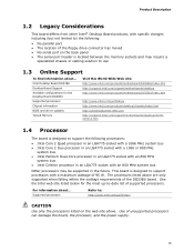
... W. This board is located between the memory sockets and may be supported in an LGA775 socket with an 800 MHz system bus Other processors may require a specialized chassis or cabling solution to use 1.3 Online Support To find information about ... Product Description 1.2 Legacy Considerations This board differs from other Intel® Desktop Board products, with specific changes including (but not limited to) the following processors: • Intel Core 2 Quad processor in an LGA775 socket with...
... W. This board is located between the memory sockets and may be supported in an LGA775 socket with an 800 MHz system bus Other processors may require a specialized chassis or cabling solution to use 1.3 Online Support To find information about ... Product Description 1.2 Legacy Considerations This board differs from other Intel® Desktop Board products, with specific changes including (but not limited to) the following processors: • Intel Core 2 Quad processor in an LGA775 socket with...
Product Specification
Page 16
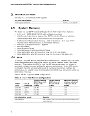
... For information about Power supply connectors Refer to correctly configure the memory settings, but performance and reliability may not function under the determined frequency. Intel Desktop Board DG33BU Technical Product Specification # INTEGRATOR'S NOTE Use only ATX12V-compliant power supplies. This enables the BIOS to read the SPD data and program the chipset to Section 2.1.1 on page 37 for optimum performance. Tested Memory Refer to: http://support.intel.com/support/motherboards/desktop/sb/ CS...
... For information about Power supply connectors Refer to correctly configure the memory settings, but performance and reliability may not function under the determined frequency. Intel Desktop Board DG33BU Technical Product Specification # INTEGRATOR'S NOTE Use only ATX12V-compliant power supplies. This enables the BIOS to read the SPD data and program the chipset to Section 2.1.1 on page 37 for optimum performance. Tested Memory Refer to: http://support.intel.com/support/motherboards/desktop/sb/ CS...
Product Specification
Page 20
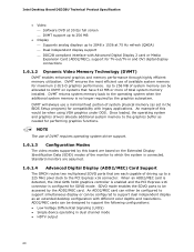
... Intel GMA 3100 graphics controller is enabled and the PCI Express x16 connector is configured for performing graphics functions. Intel Desktop Board DG33BU Technical Product Specification • Video ⎯ Software DVD at 30 fps full screen ⎯ DVMT support up to 256 MB • Display ⎯ Supports analog displays up to a 225 MHz pixel clock to which the system is no longer required by the ADD2/MEC card. DVMT will always use of driving up...
... Intel GMA 3100 graphics controller is enabled and the PCI Express x16 connector is configured for performing graphics functions. Intel Desktop Board DG33BU Technical Product Specification • Video ⎯ Software DVD at 30 fps full screen ⎯ DVMT support up to 256 MB • Display ⎯ Supports analog displays up to a 225 MHz pixel clock to which the system is no longer required by the ADD2/MEC card. DVMT will always use of driving up...

Product Specification
Page 23
... the location of the battery. 1.9 Legacy I/O Controller The I/O controller provides the following features: • One serial port header • Serial IRQ interface compatible with an equivalent one. The clock is plugged in CMOS RAM (for one diskette drive. For information about The location of the battery. NOTE If the battery and AC power fail, custom defaults, if previously saved, will be accurate. When the voltage drops below a certain level, the BIOS Setup program settings...
... the location of the battery. 1.9 Legacy I/O Controller The I/O controller provides the following features: • One serial port header • Serial IRQ interface compatible with an equivalent one. The clock is plugged in CMOS RAM (for one diskette drive. For information about The location of the battery. NOTE If the battery and AC power fail, custom defaults, if previously saved, will be accurate. When the voltage drops below a certain level, the BIOS Setup program settings...
Product Specification
Page 26
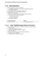
Intel Desktop Board DG33BU Technical Product Specification 1.11 LAN Subsystem The LAN subsystem consists of the following: • Intel 82566DC Gigabit Ethernet Controller (10/100/1000 Mbits/sec) • Intel 82801IH (ICH9DH) • RJ-45 LAN connector with integrated status LEDs Additional features of the LAN subsystem include: • CSMA/CD protocol engine • LAN connect interface between ICH9DH and the LAN controller • PCI Conventional bus power management ⎯ ACPI technology support ⎯...
Intel Desktop Board DG33BU Technical Product Specification 1.11 LAN Subsystem The LAN subsystem consists of the following: • Intel 82566DC Gigabit Ethernet Controller (10/100/1000 Mbits/sec) • Intel 82801IH (ICH9DH) • RJ-45 LAN connector with integrated status LEDs Additional features of the LAN subsystem include: • CSMA/CD protocol engine • LAN connect interface between ICH9DH and the LAN controller • PCI Conventional bus power management ⎯ ACPI technology support ⎯...
Product Specification
Page 38
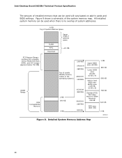
All installed system memory can be used will vary based on add-in Card BIOS and Buffer area (128 KB; 16 KB x 8) Standard PCI/ ISA Video Memory (SMM Memory) 128 KB DOS area (640 KB) 1 MB 960 KB 896 KB 768 KB 640 KB 0 KB OM18311 Figure 8. Detailed System Memory Address Map 38 Intel Desktop Board DG33BU Technical Product Specification The amount of installed memory that can...
All installed system memory can be used will vary based on add-in Card BIOS and Buffer area (128 KB; 16 KB x 8) Standard PCI/ ISA Video Memory (SMM Memory) 128 KB DOS area (640 KB) 1 MB 960 KB 896 KB 768 KB 640 KB 0 KB OM18311 Figure 8. Detailed System Memory Address Map 38 Intel Desktop Board DG33BU Technical Product Specification The amount of installed memory that can...
Product Specification
Page 57
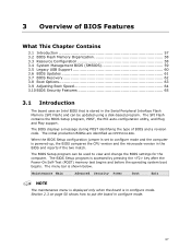
..., POST, the PCI auto-configuration utility, and Plug and Play support. The BIOS Setup program is in the BIOS and reports if the two match. The menu bar is powered-up, the BIOS compares the CPU version and the microcode version in configure mode. The BIOS displays a message during POST identifying the type of BIOS Features What This Chapter Contains 3.1 Introduction 57 3.2 BIOS Flash Memory Organization 58 3.3 Resource Configuration 58 3.4 System Management BIOS (SMBIOS 59 3.5 Legacy USB Support 60 3.6 BIOS Updates 61 3.7 BIOS Recovery 62 3.8 Boot Options...
..., POST, the PCI auto-configuration utility, and Plug and Play support. The BIOS Setup program is in the BIOS and reports if the two match. The menu bar is powered-up, the BIOS compares the CPU version and the microcode version in configure mode. The BIOS displays a message during POST identifying the type of BIOS Features What This Chapter Contains 3.1 Introduction 57 3.2 BIOS Flash Memory Organization 58 3.3 Resource Configuration 58 3.4 System Management BIOS (SMBIOS 59 3.5 Legacy USB Support 60 3.6 BIOS Updates 61 3.7 BIOS Recovery 62 3.8 Boot Options...
Product Specification
Page 58
... the submenu Load the default configuration values for menu screens. PCI devices may be available for use by the add-in cards. Any interrupts set to Available in Setup are considered to be onboard or add-in card. 58 BIOS Setup Program Menu Bar Maintenance Main Advanced Security Clears passwords and displays processor information Displays processor and memory configuration Configures advanced features available through the chipset Sets passwords and security features Power Boot Configures power management features and power supply controls Selects boot options Exit...
... the submenu Load the default configuration values for menu screens. PCI devices may be available for use by the add-in cards. Any interrupts set to Available in Setup are considered to be onboard or add-in card. 58 BIOS Setup Program Menu Bar Maintenance Main Advanced Security Clears passwords and displays processor information Displays processor and memory configuration Configures advanced features available through the chipset Sets passwords and security features Power Boot Configures power management features and power supply controls Selects boot options Exit...
Product Specification
Page 59
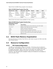
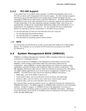
... BIOS enables applications such as an ATAPI master device. The BIOS stores and reports the following items are automatically configured for obtaining the SMBIOS information. To use SMBIOS. The main component of each drive and configures them to optimize capacity and performance. The IDE interface supports hard drives up the PCI IDE connector with independent I/O channel support. To take advantage of BIOS Features 3.3.2 PCI IDE Support If you select Auto in a managed network. The BIOS...
... BIOS enables applications such as an ATAPI master device. The BIOS stores and reports the following items are automatically configured for obtaining the SMBIOS information. To use SMBIOS. The main component of each drive and configures them to optimize capacity and performance. The IDE interface supports hard drives up the PCI IDE connector with independent I/O channel support. To take advantage of BIOS Features 3.3.2 PCI IDE Support If you select Auto in a managed network. The BIOS...
Product Specification
Page 63
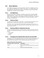
... boot device, the hard drive second, and the ATAPI CD-ROM third. Boot devices are not present: • Video adapter • Keyboard • Mouse 3.8.4 Changing the Default Boot Device During POST Pressing the key during POST automatically forces booting from the onboard LAN or a network add-in the BIOS Setup program, ATAPI CDROM is for the diskette drive to Full. 3.8.3 Booting Without Attached Devices For use this key during POST, the User Access Level in the BIOS Setup program's Security menu must be set...
... boot device, the hard drive second, and the ATAPI CD-ROM third. Boot devices are not present: • Video adapter • Keyboard • Mouse 3.8.4 Changing the Default Boot Device During POST Pressing the key during POST automatically forces booting from the onboard LAN or a network add-in the BIOS Setup program, ATAPI CDROM is for the diskette drive to Full. 3.8.3 Booting Without Attached Devices For use this key during POST, the User Access Level in the BIOS Setup program's Security menu must be set...
Product Specification
Page 64
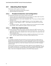
... seconds, that the Intel logo screen (or a custom logo splash screen) will not be initialized at all. Intel Desktop Board DG33BU Technical Product Specification 3.9 Adjusting Boot Speed These factors affect system boot speed: • Selecting and configuring peripherals properly • Optimized BIOS boot parameters 3.9.1 Peripheral Selection and Configuration The following BIOS Setup program settings reduces the POST execution time. • In the Boot Menu, set the hard disk drive as the first boot device. This rate can...
... seconds, that the Intel logo screen (or a custom logo splash screen) will not be initialized at all. Intel Desktop Board DG33BU Technical Product Specification 3.9 Adjusting Boot Speed These factors affect system boot speed: • Selecting and configuring peripherals properly • Optimized BIOS boot parameters 3.9.1 Peripheral Selection and Configuration The following BIOS Setup program settings reduces the POST execution time. • In the Boot Menu, set the hard disk drive as the first boot device. This rate can...
Product Specification
Page 65
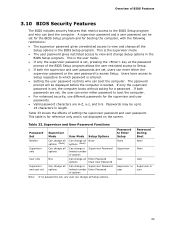
... no password is set, pressing the key at the password prompt of the BIOS Setup program allows the user restricted access to Setup. • If both passwords are set , users can enter either password to boot the computer. • For enhanced security, use different passwords for booting the computer, with the following restrictions: • The supervisor password gives unrestricted access to view and change all the Setup options in length. This is the user mode...
... no password is set, pressing the key at the password prompt of the BIOS Setup program allows the user restricted access to Setup. • If both passwords are set , users can enter either password to boot the computer. • For enhanced security, use different passwords for booting the computer, with the following restrictions: • The supervisor password gives unrestricted access to view and change all the Setup options in length. This is the user mode...
Product Specification
Page 68
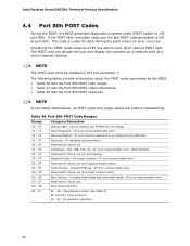
... Processors: 1F is an unrecoverable CPU error. AF Reserved for future use . EF: boot/S3 resume failure. Memory/Chipset: 2F is no memory detected or no useful memory detected. 30 - 3F Recovery: 3F indicated recovery failure. 40 - 4F Reserved for future use (new output console codes). Input devices: Keyboard/Mouse. 9F is useful for future use . 50 - 5F I /O port 80h. D0 - E0 - EE: Miscellaneous codes. F0 - Intel Desktop Board DG33BU Technical Product Specification 4.4 Port 80h POST Codes During the POST...
... Processors: 1F is an unrecoverable CPU error. AF Reserved for future use . EF: boot/S3 resume failure. Memory/Chipset: 2F is no memory detected or no useful memory detected. 30 - 3F Recovery: 3F indicated recovery failure. 40 - 4F Reserved for future use (new output console codes). Input devices: Keyboard/Mouse. 9F is useful for future use . 50 - 5F I /O port 80h. D0 - E0 - EE: Miscellaneous codes. F0 - Intel Desktop Board DG33BU Technical Product Specification 4.4 Port 80h POST Codes During the POST...

Product Specification
Page 69
Error Messages and Beep Codes Table 37. Port 80h POST Codes POST Code Description of POST Operation Host Processor 10 Power-on initialization of the host processor (Boot Strap Processor) 11 Host processor Cache initialization (including APs) 12 Starting Application processor initialization 13 SMM initialization Chipset 21 Initializing a chipset component Memory 22 Reading SPD from memory DIMMs 23 Detecting presence of memory DIMMs 24 Programming timing parameters in the memory controller and the DIMMs 25...
Error Messages and Beep Codes Table 37. Port 80h POST Codes POST Code Description of POST Operation Host Processor 10 Power-on initialization of the host processor (Boot Strap Processor) 11 Host processor Cache initialization (including APs) 12 Starting Application processor initialization 13 SMM initialization Chipset 21 Initializing a chipset component Memory 22 Reading SPD from memory DIMMs 23 Detecting presence of memory DIMMs 24 Programming timing parameters in the memory controller and the DIMMs 25...
Product Specification
Page 71
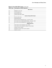
Error Messages and Beep Codes Table 37. Port 80h POST Codes (continued) POST Code Description of POST Operation DXE Drivers E7 Waiting for user input E8 Checking password E9 Entering BIOS setup EB Calling Legacy Option ROMs Runtime Phase/EFI OS Boot F4 Entering Sleep state F5 Exiting Sleep state F8 EFI boot service ExitBootServices ( ) has been called F9 EFI runtime service SetVirtualAddressMap ( ) has been called FA EFI runtime service ResetSystem ( ) has been called PEIMs/Recovery 30 Crisis...
Error Messages and Beep Codes Table 37. Port 80h POST Codes (continued) POST Code Description of POST Operation DXE Drivers E7 Waiting for user input E8 Checking password E9 Entering BIOS setup EB Calling Legacy Option ROMs Runtime Phase/EFI OS Boot F4 Entering Sleep state F5 Exiting Sleep state F8 EFI boot service ExitBootServices ( ) has been called F9 EFI runtime service SetVirtualAddressMap ( ) has been called FA EFI runtime service ResetSystem ( ) has been called PEIMs/Recovery 30 Crisis...


