
Product Specification
Page 5
...Board Layout 12 1.1.4 Block Diagram 14 1.2 Online Support ...15 1.3 Processor ...15 1.4 System Memory ...16 1.4.1 Memory Configurations 17 1.5 Intel® 945G Chipset ...21 1.5.1 Intel 945G Graphics Subsystem 21 1.5.2 USB ...23 1.5.3 IDE Support 24 1.5.4 Real-Time Clock, CMOS SRAM, and Battery 26 1.6 PCI Express Connectors 26 1.7 IEEE-1394a Connectors (Optional 26 1.8 Legacy I/O Controller 27 1.8.1 Serial Port...27 1.8.2 Parallel Port 27 1.8.3 Diskette Drive Controller 27 1.8.4 Keyboard and Mouse Interface 27 1.9 Audio Subsystem ...28 1.9.1 Audio Subsystem Software 28 1.9.2 Audio...
...Board Layout 12 1.1.4 Block Diagram 14 1.2 Online Support ...15 1.3 Processor ...15 1.4 System Memory ...16 1.4.1 Memory Configurations 17 1.5 Intel® 945G Chipset ...21 1.5.1 Intel 945G Graphics Subsystem 21 1.5.2 USB ...23 1.5.3 IDE Support 24 1.5.4 Real-Time Clock, CMOS SRAM, and Battery 26 1.6 PCI Express Connectors 26 1.7 IEEE-1394a Connectors (Optional 26 1.8 Legacy I/O Controller 27 1.8.1 Serial Port...27 1.8.2 Parallel Port 27 1.8.3 Diskette Drive Controller 27 1.8.4 Keyboard and Mouse Interface 27 1.9 Audio Subsystem ...28 1.9.1 Audio Subsystem Software 28 1.9.2 Audio...

Product Specification
Page 7
... Back Panel Connectors for Front Panel Connector 64 22. Dual Channel (Interleaved) Mode Configuration with the 8-Channel (7.1) Audio Subsystem 69 27. Detailed System Memory Address Map 48 18. Board Dimensions...68 26. LAN Connector LED States 33 vii Contents 3.8 Adjusting Boot Speed 86 3.8.1 Peripheral Selection and Configuration 86 3.8.2 BIOS Boot Optimizations 86 3.9 BIOS Security Features 87 4 Error Messages and Beep Codes 4.1 Speaker ...89 4.2 BIOS Beep Codes...89 4.3 BIOS Error Messages 89 4.4 Port 80h POST Codes 90 Figures 1. Board Components ...12 2. Connection Diagram...
... Back Panel Connectors for Front Panel Connector 64 22. Dual Channel (Interleaved) Mode Configuration with the 8-Channel (7.1) Audio Subsystem 69 27. Detailed System Memory Address Map 48 18. Board Dimensions...68 26. LAN Connector LED States 33 vii Contents 3.8 Adjusting Boot Speed 86 3.8.1 Peripheral Selection and Configuration 86 3.8.2 BIOS Boot Optimizations 86 3.9 BIOS Security Features 87 4 Error Messages and Beep Codes 4.1 Speaker ...89 4.2 BIOS Beep Codes...89 4.3 BIOS Error Messages 89 4.4 Port 80h POST Codes 90 Figures 1. Board Components ...12 2. Connection Diagram...

Product Specification
Page 8
Effects of Pressing the Power Switch 39 8. System Memory Map 49 11. Front Panel Audio Connector 60 20. Auxiliary Front Panel Power/Sleep LED Connector 63 29. BIOS Setup Configuration Jumper Settings 67 33. BIOS Setup Program Function Keys 82 42. Boot Device Menu Options 85 43. Port 80h POST Code Ranges 90 47. Serial ATA Connectors 60 23. Processor Fan Connector 61 24. States for Components 75 36. Beep Codes ...89 45. Typical Port 80h POST Sequence 94 viii LAN Connector LED States 34 7. Back Panel Connectors Shown in Figure...
Effects of Pressing the Power Switch 39 8. System Memory Map 49 11. Front Panel Audio Connector 60 20. Auxiliary Front Panel Power/Sleep LED Connector 63 29. BIOS Setup Configuration Jumper Settings 67 33. BIOS Setup Program Function Keys 82 42. Boot Device Menu Options 85 43. Port 80h POST Code Ranges 90 47. Serial ATA Connectors 60 23. Processor Fan Connector 61 24. States for Components 75 36. Beep Codes ...89 45. Typical Port 80h POST Sequence 94 viii LAN Connector LED States 34 7. Back Panel Connectors Shown in Figure...

Product Specification
Page 10
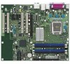
... USB ports • One serial port • One parallel port • Four Serial ATA interfaces • One Parallel ATA IDE interface with UDMA 33, ATA-66/100 support • One diskette drive interface • PS/2 keyboard and mouse ports LAN Support Refer to monitor fan activity • Fan speed control 10 Intel Desktop Board D945GNT Technical Product Specification 1.1 Overview 1.1.1 Feature Summary Table 1 summarizes the major features of audio subsystem options Legacy I/O Control Legacy I /O Controller Hub (ICH7) Video Intel® GMA950 onboard graphics...
... USB ports • One serial port • One parallel port • Four Serial ATA interfaces • One Parallel ATA IDE interface with UDMA 33, ATA-66/100 support • One diskette drive interface • PS/2 keyboard and mouse ports LAN Support Refer to monitor fan activity • Fan speed control 10 Intel Desktop Board D945GNT Technical Product Specification 1.1 Overview 1.1.1 Feature Summary Table 1 summarizes the major features of audio subsystem options Legacy I/O Control Legacy I /O Controller Hub (ICH7) Video Intel® GMA950 onboard graphics...

Product Specification
Page 11
... The board provides one of the following: • Gigabit (10/100/1000 Mbits/sec) LAN subsystem using the Intel® 82573E/82573V/82574V Gigabit Ethernet Controller • 10/100 Mbits/sec LAN subsystem using the Intel® 82562GX/82562GZ Platform LAN Connect (PLC) device SATA RAID Intel® 82801GR I/O Controller Hub (ICH7-R) for RAID support (levels 0,1, 0+1, and 5) on the SATA interface SCSI Hard Drive Activity LED Connector Allows add-in all marketing channels...
... The board provides one of the following: • Gigabit (10/100/1000 Mbits/sec) LAN subsystem using the Intel® 82573E/82573V/82574V Gigabit Ethernet Controller • 10/100 Mbits/sec LAN subsystem using the Intel® 82562GX/82562GZ Platform LAN Connect (PLC) device SATA RAID Intel® 82801GR I/O Controller Hub (ICH7-R) for RAID support (levels 0,1, 0+1, and 5) on the SATA interface SCSI Hard Drive Activity LED Connector Allows add-in all marketing channels...

Product Specification
Page 14
...IDE Connector Parallel ATA IDE Interface LGA775 Processor Socket System Bus (1066/800/533 MHz) PCI Express x16 Interface PCI Express x16 Connector Intel 945G Chipset Intel 82945G Graphics and Memory Controller Hub (GMCH) Gigabit Ethernet Controller (Optional) LAN Connector USB Back Panel/Front Panel USB Ports Legacy I/O Controller LPC Bus Serial Port Parallel Port PS/2 Mouse PS/2 Keyboard Diskette Drive Connector Intel 82801G I/O Controller Hub (ICH7) Serial Peripheral Interface (SPI) Flash Device DMI Interconnect High Definition Audio Link LAN Connect Interface VGA Port Channel...
...IDE Connector Parallel ATA IDE Interface LGA775 Processor Socket System Bus (1066/800/533 MHz) PCI Express x16 Interface PCI Express x16 Connector Intel 945G Chipset Intel 82945G Graphics and Memory Controller Hub (GMCH) Gigabit Ethernet Controller (Optional) LAN Connector USB Back Panel/Front Panel USB Ports Legacy I/O Controller LPC Bus Serial Port Parallel Port PS/2 Mouse PS/2 Keyboard Diskette Drive Connector Intel 82801G I/O Controller Hub (ICH7) Serial Peripheral Interface (SPI) Flash Device DMI Interconnect High Definition Audio Link LAN Connect Interface VGA Port Channel...

Product Specification
Page 16
...-ECC DIMMs • Serial Presence Detect • DDR2 667, DDR2 533, or DDR2 400 MHz SDRAM DIMMs NOTES • Remove the PCI Express x16 video card before installing or upgrading memory to accurately configure memory settings for additional information on the total amount of address space is available. Intel Desktop Board D945GNT Technical Product Specification 1.4 System Memory The board has four DIMM sockets and support the following memory features: • 1.8 V (only...
...-ECC DIMMs • Serial Presence Detect • DDR2 667, DDR2 533, or DDR2 400 MHz SDRAM DIMMs NOTES • Remove the PCI Express x16 video card before installing or upgrading memory to accurately configure memory settings for additional information on the total amount of address space is available. Intel Desktop Board D945GNT Technical Product Specification 1.4 System Memory The board has four DIMM sockets and support the following memory features: • 1.8 V (only...

Product Specification
Page 21
...* version 1.4 support with DMI interconnect The GMCH component provides interfaces to http://developer.intel.com/ Chapter 2 1.5.1 Intel 945G Graphics Subsystem The Intel 945G chipset contains two separate, mutually exclusive graphics options. When a PCI Express x16 add-in card can be used by the chipset Refer to the CPU, memory, PCI Express, and the DMI interconnect. The ICH7 is disabled. 1.5.1.1 Intel® GMA950 Graphics Controller The Intel GMA950 graphics controller features the following devices: • Intel 82945G Graphics Memory Controller Hub...
...* version 1.4 support with DMI interconnect The GMCH component provides interfaces to http://developer.intel.com/ Chapter 2 1.5.1 Intel 945G Graphics Subsystem The Intel 945G chipset contains two separate, mutually exclusive graphics options. When a PCI Express x16 add-in card can be used by the chipset Refer to the CPU, memory, PCI Express, and the DMI interconnect. The ICH7 is disabled. 1.5.1.1 Intel® GMA950 Graphics Controller The Intel GMA950 graphics controller features the following devices: • Intel 82945G Graphics Memory Controller Hub...

Product Specification
Page 22
... 15 1.5.1.2 Dynamic Video Memory Technology (DVMT) DVMT enables enhanced graphics and memory performance through Direct AGP, and highly efficient memory utilization. Once loaded, the operating system and graphics drivers allocate additional system memory to the graphics buffer as set in and DVI digital display connections ⎯ Supports flat panels up to 224 MB • Intel® Zoom Utility For information about DVMT Obtaining graphics software and utilities Refer to 224 MB of total installed system memory.
... 15 1.5.1.2 Dynamic Video Memory Technology (DVMT) DVMT enables enhanced graphics and memory performance through Direct AGP, and highly efficient memory utilization. Once loaded, the operating system and graphics drivers allocate additional system memory to the graphics buffer as set in and DVI digital display connections ⎯ Supports flat panels up to 224 MB • Intel® Zoom Utility For information about DVMT Obtaining graphics software and utilities Refer to 224 MB of total installed system memory.

Product Specification
Page 25
... LED connector The signal names of all data on each drive, read from the logical drive, both drives operate in a RAID 1 configuration. • RAID 0+1 (or RAID 10) - This provides the highest performance with data striping (RAID 0) into a single array. Data is a 1 x 2-pin connector that allows an add-in hard drive controller or the onboard IDE controller (Parallel ATA or Serial ATA). RAID 0+1 utilizes several drives and distributes parity among the drives; RAID 5 requires the use...
... LED connector The signal names of all data on each drive, read from the logical drive, both drives operate in a RAID 1 configuration. • RAID 0+1 (or RAID 10) - This provides the highest performance with data striping (RAID 0) into a single array. Data is a 1 x 2-pin connector that allows an add-in hard drive controller or the onboard IDE controller (Parallel ATA or Serial ATA). RAID 0+1 utilizes several drives and distributes parity among the drives; RAID 5 requires the use...
Product Specification
Page 32
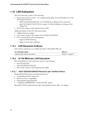
... Standard Format (ASF) 1.03 support. 32 Intel Desktop Board D945GNT Technical Product Specification 1.10 LAN Subsystem The LAN subsystem consists of the following functions: • 10/100 Ethernet LAN connectivity • Full device driver compatibility • Programmable transit threshold • Configuration EEPROM that supports the 82562GX and 82562GZ • PCI Conventional bus power management ⎯ Supports ACPI technology ⎯ Supports LAN wake capabilities 1.10.1 LAN Subsystem Software LAN software and drivers are available from Intel's World Wide Web site...
... Standard Format (ASF) 1.03 support. 32 Intel Desktop Board D945GNT Technical Product Specification 1.10 LAN Subsystem The LAN subsystem consists of the following functions: • 10/100 Ethernet LAN connectivity • Full device driver compatibility • Programmable transit threshold • Configuration EEPROM that supports the 82562GX and 82562GZ • PCI Conventional bus power management ⎯ Supports ACPI technology ⎯ Supports LAN wake capabilities 1.10.1 LAN Subsystem Software LAN software and drivers are available from Intel's World Wide Web site...

Product Specification
Page 48
... be used will vary based on add-in Card BIOS and Buffer area (128 KB; 16 KB x 8) Standard PCI/ ISA Video Memory (SMM Memory) 128 KB DOS area (640 KB) 1 MB 960 KB 896 KB 768 KB 640 KB 0 KB OM17140 Figure 17. Detailed System Memory Address Map 48 Intel Desktop Board D945GNT Technical Product Specification • MCH base address registers, internal graphics ranges, PCI Express ports...
... be used will vary based on add-in Card BIOS and Buffer area (128 KB; 16 KB x 8) Standard PCI/ ISA Video Memory (SMM Memory) 128 KB DOS area (640 KB) 1 MB 960 KB 896 KB 768 KB 640 KB 0 KB OM17140 Figure 17. Detailed System Memory Address Map 48 Intel Desktop Board D945GNT Technical Product Specification • MCH base address registers, internal graphics ranges, PCI Express ports...

Product Specification
Page 51
...Express port 3 PCI Express port 4 USB UHCI controller 1 USB UHCI controller 2 USB UHCI controller 3 USB UHCI controller 4 EHCI controller PCI bridge PCI controller Parallel ATA IDE controller Serial ATA controller SMBus controller Gigabit LAN controller (if present) PCI Conventional bus connector 1 PCI Conventional bus connector 2 PCI Conventional bus connector 3 PCI Conventional bus connector 4 IEEE-1394a controller (if present) Intel 82562 10/100 Mbits/sec LAN PLC (if present) Notes: 1. Present only when a PCI Express x16 graphics card is dynamic and can change based on add-in cards used...
...Express port 3 PCI Express port 4 USB UHCI controller 1 USB UHCI controller 2 USB UHCI controller 3 USB UHCI controller 4 EHCI controller PCI bridge PCI controller Parallel ATA IDE controller Serial ATA controller SMBus controller Gigabit LAN controller (if present) PCI Conventional bus connector 1 PCI Conventional bus connector 2 PCI Conventional bus connector 3 PCI Conventional bus connector 4 IEEE-1394a controller (if present) Intel 82562 10/100 Mbits/sec LAN PLC (if present) Notes: 1. Present only when a PCI Express x16 graphics card is dynamic and can change based on add-in cards used...

Product Specification
Page 55
... • 6-channel (5.1) audio subsystem (three analog audio output connectors), described on page 57 55 The connectors can be divided into these connectors to power devices external to the computer's chassis. The configurations are not overcurrent protected and should connect only to the computer, the power cable, and the external devices themselves. The other internal connectors are as fans and internal peripherals. Do not use these groups: • Back panel I/O connectors (see...
... • 6-channel (5.1) audio subsystem (three analog audio output connectors), described on page 57 55 The connectors can be divided into these connectors to power devices external to the computer's chassis. The configurations are not overcurrent protected and should connect only to the computer, the power cable, and the external devices themselves. The other internal connectors are as fans and internal peripherals. Do not use these groups: • Back panel I/O connectors (see...
Product Specification
Page 81
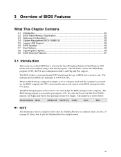
...3.5 Legacy USB Support...83 3.6 BIOS Updates ...84 3.7 Boot Options ...85 3.8 Adjusting Boot Speed 86 3.9 BIOS Security Features 87 3.1 Introduction The boards use an Intel BIOS that is poweredup, the BIOS compares the CPU version and the microcode version in the Serial Peripheral Interface Flash Memory (SPI Flash) and can be updated using a disk-based program. 3 Overview of BIOS and a revision code. When the BIOS Setup configuration jumper is set to view and change the BIOS settings for the computer. The SPI Flash contains the BIOS Setup program, POST, the PCI auto-configuration...
...3.5 Legacy USB Support...83 3.6 BIOS Updates ...84 3.7 Boot Options ...85 3.8 Adjusting Boot Speed 86 3.9 BIOS Security Features 87 3.1 Introduction The boards use an Intel BIOS that is poweredup, the BIOS compares the CPU version and the microcode version in the Serial Peripheral Interface Flash Memory (SPI Flash) and can be updated using a disk-based program. 3 Overview of BIOS and a revision code. When the BIOS Setup configuration jumper is set to view and change the BIOS settings for the computer. The SPI Flash contains the BIOS Setup program, POST, the PCI auto-configuration...

Product Specification
Page 82
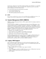
... sets up the PCI IDE connector with independent I /O space, and other system resources. When a user turns on the system after adding a PCI card, the BIOS automatically configures interrupts, the I /O channel support. Table 40. The interface also supports second-generation SATA drives. Intel Desktop Board D945GNT Technical Product Specification Table 40 lists the BIOS Setup program menu features. PCI devices may be available for the current menu Save the current values and exits the BIOS Setup program Exits the menu 3.2 BIOS Flash Memory...
... sets up the PCI IDE connector with independent I /O space, and other system resources. When a user turns on the system after adding a PCI card, the BIOS automatically configures interrupts, the I /O channel support. Table 40. The interface also supports second-generation SATA drives. Intel Desktop Board D945GNT Technical Product Specification Table 40 lists the BIOS Setup program menu features. PCI devices may be available for the current menu Save the current values and exits the BIOS Setup program Exits the menu 3.2 BIOS Flash Memory...
Product Specification
Page 83
... power to PIO Mode 3 or 4, depending on the capability of the drive. The BIOS stores and reports the following items are not yet available. POST begins. 3. The BIOS enables applications such as Windows NT*, require an additional interface for system components. POST completes. 83 Legacy USB support is enabled by specifying manual configuration in a managed network. For example, do not connect an ATA hard drive as a slave to be used...
... power to PIO Mode 3 or 4, depending on the capability of the drive. The BIOS stores and reports the following items are not yet available. POST begins. 3. The BIOS enables applications such as Windows NT*, require an additional interface for system components. POST completes. 83 Legacy USB support is enabled by specifying manual configuration in a managed network. For example, do not connect an ATA hard drive as a slave to be used...

Product Specification
Page 86
... seen. In the Boot Menu: • Set the hard disk drive as logo displays, screen repaints, or mode changes in adapter features, such as the first boot device. Some monitors initialize and communicate with minimum initialization times can influence POST execution time. • Eliminate unnecessary add-in POST. Intel Desktop Board D945GNT Technical Product Specification 3.8 Adjusting Boot Speed These factors affect system boot speed: • Selecting and configuring peripherals properly • Optimized BIOS boot parameters 3.8.1 Peripheral...
... seen. In the Boot Menu: • Set the hard disk drive as logo displays, screen repaints, or mode changes in adapter features, such as the first boot device. Some monitors initialize and communicate with minimum initialization times can influence POST execution time. • Eliminate unnecessary add-in POST. Intel Desktop Board D945GNT Technical Product Specification 3.8 Adjusting Boot Speed These factors affect system boot speed: • Selecting and configuring peripherals properly • Optimized BIOS boot parameters 3.8.1 Peripheral...

Product Specification
Page 90
... indicated recovery failure. This code is an unrecoverable CPU error. BF C0 - Host Processors: 1F is useful for future use. Reserved for determining the point where an error occurred. E0 - Intel Desktop Board D945GNT Technical Product Specification 4.4 Port 80h POST Codes During the POST, the BIOS generates diagnostic progress codes (POST-codes) to I /O Busses: PCI, USB, ISA, ATA, etc. 5F is an unrecoverable error. CF D0 - Memory/Chipset: 2F is no memory detected or no useful memory detected. I /O port 80h. Boot device...
... indicated recovery failure. This code is an unrecoverable CPU error. BF C0 - Host Processors: 1F is useful for future use. Reserved for determining the point where an error occurred. E0 - Intel Desktop Board D945GNT Technical Product Specification 4.4 Port 80h POST Codes During the POST, the BIOS generates diagnostic progress codes (POST-codes) to I /O Busses: PCI, USB, ISA, ATA, etc. 5F is an unrecoverable error. CF D0 - Memory/Chipset: 2F is no memory detected or no useful memory detected. I /O port 80h. Boot device...

Product Specification
Page 91
... POST Operation Host Processor Power-on initialization of the host processor (Boot Strap Processor) Host processor Cache initialization (including APs) Starting Application processor initialization SMM initialization Chipset Initializing a chipset component Memory Reading SPD from memory DIMMs Detecting presence of memory DIMMs Programming timing parameters in the memory controller and the DIMMs Configuring memory Optimizing memory settings Initializing memory, such as ECC init Testing memory PCI Bus Enumerating PCI busses Allocating resources to PCI bus Hot Plug PCI controller initialization...
... POST Operation Host Processor Power-on initialization of the host processor (Boot Strap Processor) Host processor Cache initialization (including APs) Starting Application processor initialization SMM initialization Chipset Initializing a chipset component Memory Reading SPD from memory DIMMs Detecting presence of memory DIMMs Programming timing parameters in the memory controller and the DIMMs Configuring memory Optimizing memory settings Initializing memory, such as ECC init Testing memory PCI Bus Enumerating PCI busses Allocating resources to PCI bus Hot Plug PCI controller initialization...


