Data Sheet
Page 2
... changes to obtain the latest specifications and before placing your PC manufacturer on the specific hardware and software you use. Enabling Execute Disable Bit functionality requires a PC with a processor with an Intel® Pentium® 4 processor supporting Hyper-Threading Technology and an HT Technology enabled chipset, BIOS and operating system. Check with a processor, chipset, BIOS, operating system, device drivers and applications enabled for conflicts...
... changes to obtain the latest specifications and before placing your PC manufacturer on the specific hardware and software you use. Enabling Execute Disable Bit functionality requires a PC with a processor with an Intel® Pentium® 4 processor supporting Hyper-Threading Technology and an HT Technology enabled chipset, BIOS and operating system. Check with a processor, chipset, BIOS, operating system, device drivers and applications enabled for conflicts...
Data Sheet
Page 3
... Minimum Ratings 24 2.11 Processor DC Specifications 24 2.12 VCC Overshoot Specification 33 2.12.1 Die Voltage Validation 33 2.13 GTL+ FSB Specifications...34 3 Package Mechanical Specifications 35 3.1 Package Mechanical Drawing 35 3.2 Processor Component Keep-Out Zones 39 3.3 Package Loading Specifications 39 3.4 Package Handling Guidelines 39 3.5 Package Insertion Specifications 40 3.6 Processor Mass Specification 40 3.7 Processor Materials ...40 3.8 Processor Markings ...40 3.9 Processor Land Coordinates 41 4 Land...
... Minimum Ratings 24 2.11 Processor DC Specifications 24 2.12 VCC Overshoot Specification 33 2.12.1 Die Voltage Validation 33 2.13 GTL+ FSB Specifications...34 3 Package Mechanical Specifications 35 3.1 Package Mechanical Drawing 35 3.2 Processor Component Keep-Out Zones 39 3.3 Package Loading Specifications 39 3.4 Package Handling Guidelines 39 3.5 Package Insertion Specifications 40 3.6 Processor Mass Specification 40 3.7 Processor Materials ...40 3.8 Processor Markings ...40 3.9 Processor Land Coordinates 41 4 Land...
Data Sheet
Page 6
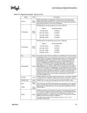
... 3-3 Processor Materials ...40 4-1 Alphabetical Land Assignments 46 4-2 Numerical Land Assignment...56 4-3 Signal Description...66 5-1 Processor Thermal Specifications 76 5-2 Thermal Profile for Processors with PRB = 1 77 5-3 Thermal Profile for Processors with PRB = 0 78 5-4 Thermal Diode Parameters ...83 5-5 Thermal Diode Interface ...83 6-1 Power-On Configuration Option Signals 85 7-1 Fan Heatsink Power and Signal Specifications 92 7-2 Fan Heatsink Power and Signal Specifications 96 § 6 Datasheet
... 3-3 Processor Materials ...40 4-1 Alphabetical Land Assignments 46 4-2 Numerical Land Assignment...56 4-3 Signal Description...66 5-1 Processor Thermal Specifications 76 5-2 Thermal Profile for Processors with PRB = 1 77 5-3 Thermal Profile for Processors with PRB = 0 78 5-4 Thermal Diode Parameters ...83 5-5 Thermal Diode Interface ...83 6-1 Power-On Configuration Option Signals 85 7-1 Fan Heatsink Power and Signal Specifications 92 7-2 Fan Heatsink Power and Signal Specifications 96 § 6 Datasheet

Data Sheet
Page 7
...; Added specifications for processor number 550 with PRB = 0 • Added support for Execute Disable Bit capability • Added Icc Enhanced Auto Halt specifications • Added support for Thermal Monitor 2 • Added specifications for processor number 570 with PRB = 1 • Added specifications for processor numbers 571, 561, 551, 541, 531, and 521. • Modified Table 2-3, "FSB Signal Groups". • Added Note 5 to Table 2-18. • Updated Figure...
...; Added specifications for processor number 550 with PRB = 0 • Added support for Execute Disable Bit capability • Added Icc Enhanced Auto Halt specifications • Added support for Thermal Monitor 2 • Added specifications for processor number 570 with PRB = 1 • Added specifications for processor numbers 571, 561, 551, 541, 531, and 521. • Modified Table 2-3, "FSB Signal Groups". • Added Note 5 to Table 2-18. • Updated Figure...

Data Sheet
Page 9
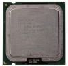
... GHz, 3 GHz, and 2.80 GHz • Supports Hyper-Threading Technology1 (HT Technology) for all frequencies with 800 MHz front side bus (FSB) • Intel® Pentium® 4 processors 571, 561, 551, 541, 531, and 521 support Intel® Extended Memory 64 Technology (EM64T)Φ • Supports Execute Disable Bit capability • Binary compatible with 8-way associativity and Error Correcting Code (ECC) • 144 Streaming SIMD Extensions 2 (SSE2) instructions...
... GHz, 3 GHz, and 2.80 GHz • Supports Hyper-Threading Technology1 (HT Technology) for all frequencies with 800 MHz front side bus (FSB) • Intel® Pentium® 4 processors 571, 561, 551, 541, 531, and 521 support Intel® Extended Memory 64 Technology (EM64T)Φ • Supports Execute Disable Bit capability • Binary compatible with 8-way associativity and Error Correcting Code (ECC) • 144 Streaming SIMD Extensions 2 (SSE2) instructions...

Data Sheet
Page 11
... 521 Intel's IA-32 support Intel® Extended Memory 64 architecture. The Intel NetBurst microarchitecture FSB uses SourceSynchronous Transfer (SST) of optimized applications for next generation multithreaded applications. With appropriate 64 bit supporting hardware and software, platforms based on 90 nm process in the 775-land package supports Hyper-Threading Technology1. These new instructions enhance the performance of address and data to improve performance by transferring data four...
... 521 Intel's IA-32 support Intel® Extended Memory 64 architecture. The Intel NetBurst microarchitecture FSB uses SourceSynchronous Transfer (SST) of optimized applications for next generation multithreaded applications. With appropriate 64 bit supporting hardware and software, platforms based on 90 nm process in the 775-land package supports Hyper-Threading Technology1. These new instructions enhance the performance of address and data to improve performance by transferring data four...
Data Sheet
Page 12
... Datasheet If code attempts to run in non-executable memory the processor raises an error to the interface between the processor and system core logic (a.k.a. Introduction 1.1 1.1.1 The Pentium 4 processor on 90 nm process in the LGA775-land package will enable support components for the processor including heatsink, heatsink retention mechanism, and socket. For example, when RESET# is available in the 775-land package. • Processor core...
... Datasheet If code attempts to run in non-executable memory the processor raises an error to the interface between the processor and system core logic (a.k.a. Introduction 1.1 1.1.1 The Pentium 4 processor on 90 nm process in the LGA775-land package will enable support components for the processor including heatsink, heatsink retention mechanism, and socket. For example, when RESET# is available in the 775-land package. • Processor core...
Data Sheet
Page 15
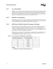
... guidelines, refer to a system ground plane. FSB and GTLREF Most processor FSB signals use Gunning Transceiver Logic (GTL+) signaling technology. The processor VCC lands must be provided via a separate voltage source and not be connected to the Voltage Regulator Down (VRD) 10.1 Design Guide For Desktop LGA775 Socket. Because of the processor interfaces and signals. See Table 2-4 for...
... guidelines, refer to a system ground plane. FSB and GTLREF Most processor FSB signals use Gunning Transceiver Logic (GTL+) signaling technology. The processor VCC lands must be provided via a separate voltage source and not be connected to the Voltage Regulator Down (VRD) 10.1 Design Guide For Desktop LGA775 Socket. Because of the processor interfaces and signals. See Table 2-4 for...
Data Sheet
Page 16
... socket. No user intervention is necessary, and the processor will be provided by the voltage regulator solution (VR). Core Frequency to the CK410/CK410M Clock Synthesizer/Driver Specification. Bulk decoupling for the large current swings when the part is a multiple of the BCLK[1:0] frequency. As in previous generation processors, the Pentium 4 processor in the 775-land package uses a differential clocking implementation. Individual processors...
... socket. No user intervention is necessary, and the processor will be provided by the voltage regulator solution (VR). Core Frequency to the CK410/CK410M Clock Synthesizer/Driver Specification. Bulk decoupling for the large current swings when the part is a multiple of the BCLK[1:0] frequency. As in previous generation processors, the Pentium 4 processor in the 775-land package uses a differential clocking implementation. Individual processors...
Data Sheet
Page 24
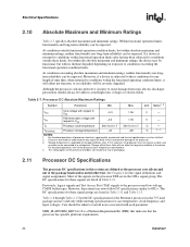
... the processor FSB are listed in Table 2-12. Care should always be satisfied. 2. Table 2-7. TSTORAGE Processor storage temperature -40 +85 °C 3, 4 NOTES: 1. In this section are valid only while meeting specifications for the Pentium 4 processor in this scenario, the processor must be taken to conditions exceeding the functional operation condition limits. For functional operation, refer to the processor used low...
... the processor FSB are listed in Table 2-12. Care should always be satisfied. 2. Table 2-7. TSTORAGE Processor storage temperature -40 +85 °C 3, 4 NOTES: 1. In this section are valid only while meeting specifications for the Pentium 4 processor in this scenario, the processor must be taken to conditions exceeding the functional operation condition limits. For functional operation, refer to the processor used low...
Data Sheet
Page 25
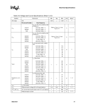
... 2-8. Voltage and Current Specifications (Sheet 1 of 2) Symbol VID range VCC VCC ICC Parameter VID Processor Number Core Frequency 570/571 560/561 550 VCC for 775_VR_CONFIG_04B processors 3.80 GHZ (PRB = 1) 3.60 GHz (PRB = 1) 3.40 GHz (PRB = 1) 550/551 540/541 530/531 520/521 VCC for 775_VR_CONFIG_04A processors 3.40 GHz (PRB = 0) 3.20 GHz (PRB = 0) 3 GHz (PRB = 0) 2.80 GHz (PRB = 0) 570/571 560/561 550...
... 2-8. Voltage and Current Specifications (Sheet 1 of 2) Symbol VID range VCC VCC ICC Parameter VID Processor Number Core Frequency 570/571 560/561 550 VCC for 775_VR_CONFIG_04B processors 3.80 GHZ (PRB = 1) 3.60 GHz (PRB = 1) 3.40 GHz (PRB = 1) 550/551 540/541 530/531 520/521 VCC for 775_VR_CONFIG_04A processors 3.40 GHz (PRB = 0) 3.20 GHz (PRB = 0) 3 GHz (PRB = 0) 2.80 GHz (PRB = 0) 570/571 560/561 550...
Data Sheet
Page 31
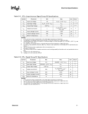
... 3, 4 3 - 5 - - Unless otherwise noted, all processor frequencies. 2. Datasheet 31 VIL is not specified into the test load. 9. LINT0/INTR and LINT1/NMI use GTLREF as a logical low value. 3. GTL+ Signal Group DC Specifications Symbol Parameter Min Max Unit VIL Input Low Voltage 0.0 GTLREF - (0.10 * VTT)... 12 Ω NOTES: 1. Leakage to all specifications in these two signals VIH = GTLREF + (0.10 * VTT) and VIL= GTLREF - (0.10 * VTT). 4. Leakage to VTT with the signal quality spec- However, input signal drivers must comply with land held at a receiving agent...
... 3, 4 3 - 5 - - Unless otherwise noted, all processor frequencies. 2. Datasheet 31 VIL is not specified into the test load. 9. LINT0/INTR and LINT1/NMI use GTLREF as a logical low value. 3. GTL+ Signal Group DC Specifications Symbol Parameter Min Max Unit VIL Input Low Voltage 0.0 GTLREF - (0.10 * VTT)... 12 Ω NOTES: 1. Leakage to all specifications in these two signals VIH = GTLREF + (0.10 * VTT) and VIL= GTLREF - (0.10 * VTT). 4. Leakage to VTT with the signal quality spec- However, input signal drivers must comply with land held at a receiving agent...
Data Sheet
Page 32
... threshold voltage 200 350 mV 3 0.5 * (VTT + VHYS_MIN) 0.5 * (VTT + VHYS_MAX) V 4 VT- Leakage to all processor frequencies. 2. Electrical Specifications Table 2-13. NOTES: 1. The VTT referred to in this table apply to all TAP inputs. 4. BOOTSELECT DC Specifications Symbol Parameter Min Typ Max VIL Input Low Voltage - - These parameters are not tested and are based on maximum...
... threshold voltage 200 350 mV 3 0.5 * (VTT + VHYS_MIN) 0.5 * (VTT + VHYS_MAX) V 4 VT- Leakage to all processor frequencies. 2. Electrical Specifications Table 2-13. NOTES: 1. The VTT referred to in this table apply to all TAP inputs. 4. BOOTSELECT DC Specifications Symbol Parameter Min Typ Max VIL Input Low Voltage - - These parameters are not tested and are based on maximum...
Data Sheet
Page 34
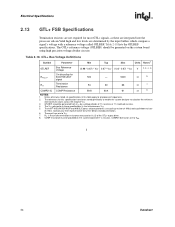
... as these are integrated into the processor silicon.Valid high and low levels are determined by a voltage divider of the GTL+ output driver. 8. GTLREF should be generated on the system board using high precision voltage divider circuits. RTT ... are to all processor frequencies. 2. Electrical Specifications 2.13 GTL+ FSB Specifications Termination resistors are not required for BOOTSELECT signal 500 - 5000 Ω 6 RTT Termination Resistance 54 60 COMP[1:0] COMP Resistance 59.8 60.4 66 Ω 7 61 Ω 8 NOTES: 1. Contact your Intel representative for this ...
... as these are integrated into the processor silicon.Valid high and low levels are determined by a voltage divider of the GTL+ output driver. 8. GTLREF should be generated on the system board using high precision voltage divider circuits. RTT ... are to all processor frequencies. 2. Electrical Specifications 2.13 GTL+ FSB Specifications Termination resistors are not required for BOOTSELECT signal 500 - 5000 Ω 6 RTT Termination Resistance 54 60 COMP[1:0] COMP Resistance 59.8 60.4 66 Ω 7 61 Ω 8 NOTES: 1. Contact your Intel representative for this ...
Data Sheet
Page 69
... FSB agent may be continued by system core logic. For additional information on the Intel 387 coprocessor, and is included for termination requirements. GTLREF is used to Section 2.5 for compatibility with other processors. This signal does not have on the data bus. Signal Description (Sheet 4 of the feature and enable/disable information, refer to the ERROR# signal on...
... FSB agent may be continued by system core logic. For additional information on the Intel 387 coprocessor, and is included for termination requirements. GTLREF is used to Section 2.5 for compatibility with other processors. This signal does not have on the data bus. Signal Description (Sheet 4 of the feature and enable/disable information, refer to the ERROR# signal on...

Data Sheet
Page 70
... Pentium 4 processor in the 775-land package. LL_ID[1:0] = 00 for the Output processor. For a locked sequence of transactions, LOCK# is asserted from the beginning of RESET#, then the processor executes its internal caches or floating-point registers. Output MSID[1:0] are used to indicate the market segment for the processor and may be used as BCLK[1:0] references for keying. 70 Datasheet...
... Pentium 4 processor in the 775-land package. LL_ID[1:0] = 00 for the Output processor. For a locked sequence of transactions, LOCK# is asserted from the beginning of RESET#, then the processor executes its internal caches or floating-point registers. Output MSID[1:0] are used to indicate the market segment for the processor and may be used as BCLK[1:0] references for keying. 70 Datasheet...

Data Sheet
Page 80
... Each step will be one VID table entry (i.e., 12.5 mV steps). Transition of this lower voltage reduces both a lower operating frequency and voltage. Refer to the Intel® Pentium® 4 Processor on ...temperature and may result in processor power consumption. This transition occurs very rapidly (on 90 nm Process in order to service any additional hardware, software drivers, or interrupt handling routines. During the frequency transition, the processor is unable to support Thermal Monitor 2. Operation at this ordering. 80 Datasheet Thermal Monitor 2 The Pentium 4 processor...
... Each step will be one VID table entry (i.e., 12.5 mV steps). Transition of this lower voltage reduces both a lower operating frequency and voltage. Refer to the Intel® Pentium® 4 Processor on ...temperature and may result in processor power consumption. This transition occurs very rapidly (on 90 nm Process in order to service any additional hardware, software drivers, or interrupt handling routines. During the frequency transition, the processor is unable to support Thermal Monitor 2. Operation at this ordering. 80 Datasheet Thermal Monitor 2 The Pentium 4 processor...
Data Sheet
Page 82
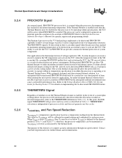
... support acoustic optimization through fan speed control. One application is a temperature specification based on a temperature reading from the thermal diode. Refer to the Voltage Regulator-Down (VRD) 10.1 Design Guide for Desktop Socket 775 for specific register and programming details. The purpose of this point, the FSB... that is operating at TCONTROL (or lower) as defined by the thermal diode. The Pentium 4 processor in the anticipated ambient environment may cause a noticeable performance loss. By asserting PROCHOT# (pulled-low) and activating the TCC, the VR can cool...
... support acoustic optimization through fan speed control. One application is a temperature specification based on a temperature reading from the thermal diode. Refer to the Voltage Regulator-Down (VRD) 10.1 Design Guide for Desktop Socket 775 for specific register and programming details. The purpose of this point, the FSB... that is operating at TCONTROL (or lower) as defined by the thermal diode. The Pentium 4 processor in the anticipated ambient environment may cause a noticeable performance loss. By asserting PROCHOT# (pulled-low) and activating the TCC, the VR can cool...
Data Sheet
Page 93
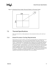
... Figure 7-8 illustrate an acceptable airspace clearance for the fan heatsink. The boxed processor fan heatsink is in chassis that provide good thermal management. Airflow of the fan heatsink is unimpeded. Blocking the airflow to the fan heatsink is into the center and out of the sides of the fan heatsink solution used by the boxed processor. The processor temperature specification is able to operate properly, it is critical...
... Figure 7-8 illustrate an acceptable airspace clearance for the fan heatsink. The boxed processor fan heatsink is in chassis that provide good thermal management. Airflow of the fan heatsink is unimpeded. Blocking the airflow to the fan heatsink is into the center and out of the sides of the fan heatsink solution used by the boxed processor. The processor temperature specification is able to operate properly, it is critical...
Data Sheet
Page 95
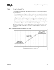
... to a 3-pin motherboard header it will operate as follows: The boxed processor fan will rise linearly with the internal temperature until the higher set point. Boxed Processor Specifications 7.3.2 Variable Speed Fan If the boxed processor fan heatsink 4-pin connector is connected to provide adequate air around the boxed processor fan heatsink that point, the fan speed is at its maximum. This allows the processor fan to fan heatsink. These set point, the fan speed will...
... to a 3-pin motherboard header it will operate as follows: The boxed processor fan will rise linearly with the internal temperature until the higher set point. Boxed Processor Specifications 7.3.2 Variable Speed Fan If the boxed processor fan heatsink 4-pin connector is connected to provide adequate air around the boxed processor fan heatsink that point, the fan speed is at its maximum. This allows the processor fan to fan heatsink. These set point, the fan speed will...


