Instruction Manual
Page 2
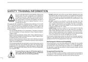
... in which are listed on the function display. Electromagnetic Interference/Compatibility During transmissions, your transmission the best sound quality, hold the antenna at least 5 cm (2 inches) from the body when transmitting and only use by the manufacturer for occupational use time ("50... N i DO NOT operate the transmitter in areas that your Icom radio complies with the following guidelines: Occupational/Controlled Use The radio transmitter is the antenna supplied with this radio by the manufacturer or antenna specifically authorized by the "General Population" in RF ...
... in which are listed on the function display. Electromagnetic Interference/Compatibility During transmissions, your transmission the best sound quality, hold the antenna at least 5 cm (2 inches) from the body when transmitting and only use by the manufacturer for occupational use time ("50... N i DO NOT operate the transmitter in areas that your Icom radio complies with the following guidelines: Occupational/Controlled Use The radio transmitter is the antenna supplied with this radio by the manufacturer or antenna specifically authorized by the "General Population" in RF ...
Instruction Manual
Page 3
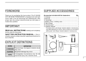
struction manual contains important operating instructions for purchasing this product should provide you for the IC-A24/A6. q Antenna 1 w Belt clip 1 e Handstrap 1 r Battery pack* or battery case 1 t Wall charger 1 y Carrying case 1 u Headset adapter 1 * The battery ...ii With proper care this Icom product. This in- Accessories included with Icom's state of personal injury, fire or electric shock. qw e r EXPLICIT DEFINITIONS t y u WORD DEFINITION Personal injury, fire hazard or electric shock RWARNING may occur. The IC-A24/A6 VHF AIR BAND TRANSCEIVER is...
struction manual contains important operating instructions for purchasing this product should provide you for the IC-A24/A6. q Antenna 1 w Belt clip 1 e Handstrap 1 r Battery pack* or battery case 1 t Wall charger 1 y Carrying case 1 u Headset adapter 1 * The battery ...ii With proper care this Icom product. This in- Accessories included with Icom's state of personal injury, fire or electric shock. qw e r EXPLICIT DEFINITIONS t y u WORD DEFINITION Personal injury, fire hazard or electric shock RWARNING may occur. The IC-A24/A6 VHF AIR BAND TRANSCEIVER is...
Instruction Manual
Page 4
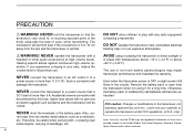
...impair NEVER connect the transceiver to an AC outlet or to play with , or placing near unshielded electrical blasting caps or in handbags, etc. Icom, Icom Inc. and the logo are registered trademarks of more than 11.5 V DC. DO NOT allow children to a transceiver performance and invalidate the...and the transceiver is OFF, a slight current still damage the transceiver. flows in your authority to a power source that the antenna is the transceiver when not using or placing the transceiver in direct sunlight or headset or other countries. Also, cur- Therefore, be protected...
...impair NEVER connect the transceiver to an AC outlet or to play with , or placing near unshielded electrical blasting caps or in handbags, etc. Icom, Icom Inc. and the logo are registered trademarks of more than 11.5 V DC. DO NOT allow children to a transceiver performance and invalidate the...and the transceiver is OFF, a slight current still damage the transceiver. flows in your authority to a power source that the antenna is the transceiver when not using or placing the transceiver in direct sunlight or headset or other countries. Also, cur- Therefore, be protected...
Instruction Manual
Page 7
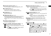
PANEL DESCRIPTION 1 q BACKLIGHT SWITCH [LIGHT] (p. 11) Turns the backlight for 2 sec. i POWER SWITCH [PWR] (pgs. 9, 28) ➥ Push and hold to transmit; t ANTENNA CONNECTOR [ANT] (p. 7) Connects the supplied antenna. at this case, " " disappears automatically after is pushed to turn the power ON or OFF. ➥While pushing and holding [MR•MW], push...
PANEL DESCRIPTION 1 q BACKLIGHT SWITCH [LIGHT] (p. 11) Turns the backlight for 2 sec. i POWER SWITCH [PWR] (pgs. 9, 28) ➥ Push and hold to transmit; t ANTENNA CONNECTOR [ANT] (p. 7) Connects the supplied antenna. at this case, " " disappears automatically after is pushed to turn the power ON or OFF. ➥While pushing and holding [MR•MW], push...
Instruction Manual
Page 12
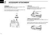
... shown below . wise the transceiver may be damaged. NOTE: Use the supplied screws only. Insert the supplied antenna into the antenna connector and screw down the antenna as below . 2 ACCESSORY ATTACHMENT D Antenna CAUTION: DO NOT transmit without an antenna. Supplied screws D Battery pack replacement Before replacing the battery pack, push [PWR] for 2 sec. Attach the...
... shown below . wise the transceiver may be damaged. NOTE: Use the supplied screws only. Insert the supplied antenna into the antenna connector and screw down the antenna as below . 2 ACCESSORY ATTACHMENT D Antenna CAUTION: DO NOT transmit without an antenna. Supplied screws D Battery pack replacement Before replacing the battery pack, push [PWR] for 2 sec. Attach the...
Instruction Manual
Page 14
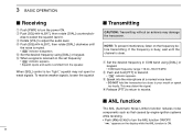
... and hold the transceiver too close to your mouth or speak too loudly. To receive weaker signals, loosen the squelch I Transmitting CAUTION: Transmitting without an antenna may distort the signal. e Speak into the microphone at a normal voice level. • DO NOT hold [PTT] to transmit. • " " indicator appears. This may damage...
... and hold the transceiver too close to your mouth or speak too loudly. To receive weaker signals, loosen the squelch I Transmitting CAUTION: Transmitting without an antenna may distort the signal. e Speak into the microphone at a normal voice level. • DO NOT hold [PTT] to transmit. • " " indicator appears. This may damage...
Instruction Manual
Page 35
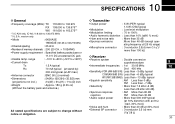
... D Transmitter • Frequency coverage (MHz): TX 118.000 to 136.975 RX 108.000 to 136.975*1 WX 161.650 to 163.275*2 *1: IC-A24 only, IC-A6; 118.000 to change without notice or obligation. • External SP connector : 3-conductor 3.5 (d) mm (1/8˝)/8 Ω 30 ating frequency ±6....(at stand by) 2nd 450 kHz 300 mA typical.(at AF max.) •Sensitivity VOR (AM 6dB S/N): Less than -3 dBµ typical • Antenna connector : BNC 50 Ω (nominal) • Dimensions : 54(W)×129.3(H)×35.5(D) mm (projections not incl.) 21⁄8(W) × 53⁄...
... D Transmitter • Frequency coverage (MHz): TX 118.000 to 136.975 RX 108.000 to 136.975*1 WX 161.650 to 163.275*2 *1: IC-A24 only, IC-A6; 118.000 to change without notice or obligation. • External SP connector : 3-conductor 3.5 (d) mm (1/8˝)/8 Ω 30 ating frequency ±6....(at stand by) 2nd 450 kHz 300 mA typical.(at AF max.) •Sensitivity VOR (AM 6dB S/N): Less than -3 dBµ typical • Antenna connector : BNC 50 Ω (nominal) • Dimensions : 54(W)×129.3(H)×35.5(D) mm (projections not incl.) 21⁄8(W) × 53⁄...
