
Installation Guide
Page 12
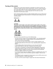
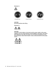
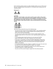
Statement 5: ≥ 55 kg (121.2 lb) CAUTION: The power control button on the device and the power switch on the power supply do not turn off the electrical current supplied to the device. The device also might have more than one power cord. Statement 4: ≥ 18 kg (39.7 lb) ≥ 32 kg (70.5 lb) CAUTION: Use safe practices when lifting. To remove all electrical current from the device, ensure that all power cords are disconnected from the power source. 2 1 x IBM System x3500 Type 7977: Installation Guide
Statement 5: ≥ 55 kg (121.2 lb) CAUTION: The power control button on the device and the power switch on the power supply do not turn off the electrical current supplied to the device. The device also might have more than one power cord. Statement 4: ≥ 18 kg (39.7 lb) ≥ 32 kg (70.5 lb) CAUTION: Use safe practices when lifting. To remove all electrical current from the device, ensure that all power cords are disconnected from the power source. 2 1 x IBM System x3500 Type 7977: Installation Guide

Installation Guide
Page 22
...easier to remove it from or install it in it is turned on your forearms. Button long-sleeved shirts before you work inside the server; do not remove the air ducts ... the component. v Remove jewelry, such as bracelets, necklaces, rings, and loose-fitting wrist watches. 8 IBM System x3500 Type 7977: Installation Guide v You can install a maximum of two IDE devices in front of the server. v There...open space around the server to allow your necktie or scarf to hang inside the server with the power on The server supports hot-swap devices and is removed. v Blue on its side. v When...
...easier to remove it from or install it in it is turned on your forearms. Button long-sleeved shirts before you work inside the server; do not remove the air ducts ... the component. v Remove jewelry, such as bracelets, necklaces, rings, and loose-fitting wrist watches. 8 IBM System x3500 Type 7977: Installation Guide v You can install a maximum of two IDE devices in front of the server. v There...open space around the server to allow your necktie or scarf to hang inside the server with the power on The server supports hot-swap devices and is removed. v Blue on its side. v When...
Installation Guide
Page 49
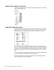
...is not shown so that a hard disk drive is in use IBM Director to visually locate the server among other servers. Hard disk drive activity LED: When this LED is off accidentally. When this button to prevent the server from being turned off , it indicates ...LEDs on and off manually. System power LED Power-control button Hard disk drive activity LED System locator LED System-information LED System-error LED DVD drive activity LED (green) USB 2 USB 1 DVD-eject button Hard disk drive status LED (amber) Hard disk drive activity LED (green) System power LED: When this disk-...
...is not shown so that a hard disk drive is in use IBM Director to visually locate the server among other servers. Hard disk drive activity LED: When this LED is off accidentally. When this button to prevent the server from being turned off , it indicates ...LEDs on and off manually. System power LED Power-control button Hard disk drive activity LED System locator LED System-information LED System-error LED DVD drive activity LED (green) USB 2 USB 1 DVD-eject button Hard disk drive status LED (amber) Hard disk drive activity LED (green) System power LED: When this disk-...
Installation Guide
Page 50
... the IBM System x Documentation CD for more information (see the Problem Determination and Service Guide on , the server power supplies... is in use . 36 IBM System x3500 Type 7977: Installation Guide System-error LED: When this LED is lit, it indicates... that the DVD drive is lit, it indicates that a system error has occurred. Check the light path diagnostic panel for additional information. System-information LED: When this connector. The event is being rebuilt. DVD-eject button: Press this button...
... the IBM System x Documentation CD for more information (see the Problem Determination and Service Guide on , the server power supplies... is in use . 36 IBM System x3500 Type 7977: Installation Guide System-error LED: When this LED is lit, it indicates... that the DVD drive is lit, it indicates that a system error has occurred. Check the light path diagnostic panel for additional information. System-information LED: When this connector. The event is being rebuilt. DVD-eject button: Press this button...
Installation Guide
Page 53
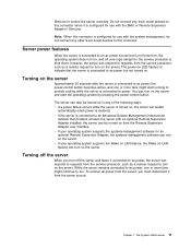
...the Remote Supervisor Adapter user interface. Note: When 4 GB or more fans might start the operating system by pressing the power-control button. Server controls, connectors, LEDs, and power 39 The power-on LED flashes to indicate that contains at least one or more of memory (physical or logical... is connected to the operating system. Turning on the server Approximately 20 seconds after the server is connected to an ac power source but is not turned on. Server power features When the server is connected to ac power, the power-control button becomes active, one server with...
...the Remote Supervisor Adapter user interface. Note: When 4 GB or more fans might start the operating system by pressing the power-control button. Server controls, connectors, LEDs, and power 39 The power-on LED flashes to indicate that contains at least one or more of memory (physical or logical... is connected to the operating system. Turning on the server Approximately 20 seconds after the server is connected to an ac power source but is not turned on. Server power features When the server is connected to ac power, the power-control button becomes active, one server with...
Installation Guide
Page 54
...Statement 5: CAUTION: The power control button on the device and the power switch on the server. v The integrated system management microprocessor can press and hold the power-control button for information about shutting down the operating system. v If the operating system stops functioning, you can...off from the service microprocessor. 40 IBM System x3500 Type 7977: Installation Guide v If the server is installed in any of the operating system, the server will be turned off automatically. To remove all power cords are disconnected from the power source. 2 1 The server ...
...Statement 5: CAUTION: The power control button on the device and the power switch on the server. v The integrated system management microprocessor can press and hold the power-control button for information about shutting down the operating system. v If the operating system stops functioning, you can...off from the service microprocessor. 40 IBM System x3500 Type 7977: Installation Guide v If the server is installed in any of the operating system, the server will be turned off automatically. To remove all power cords are disconnected from the power source. 2 1 The server ...
Installation Guide
Page 100
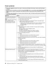
... the following components: a. If you are using an ACPI-aware operating system, suspect the System board. 86 IBM System x3500 Type 7977: Installation Guide c. If the server fails POST and the power-control button does not work (the server does not start). Power problems v Follow the suggested actions in the order in which components are field replaceable units (FRU...
... the following components: a. If you are using an ACPI-aware operating system, suspect the System board. 86 IBM System x3500 Type 7977: Installation Guide c. If the server fails POST and the power-control button does not work (the server does not start). Power problems v Follow the suggested actions in the order in which components are field replaceable units (FRU...
Installation Guide
Page 104
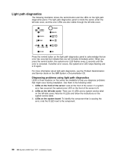
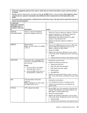
...the server are 13 LEDs and a system service label on the left -side cover. 1 POWER SUPPLY 2 CONFIG TEMP REMIND MEMORY DASD/ RAID FAN CPU S_ERR VRM PCI BUS SP BUS NMI SEE INSIDE COVER FOR MORE SERVICE INFORMATION Press the remind button on the front of the server: ...: 1. Diagnosing problems using light path diagnostics LEDs in the following illustration shows the remind button and the LEDs on the left-side cover: There are available to the component. 90 IBM System x3500 Type 7977: Installation Guide The light path diagnostics panel is inside the server under the left-side cover...
...the server are 13 LEDs and a system service label on the left -side cover. 1 POWER SUPPLY 2 CONFIG TEMP REMIND MEMORY DASD/ RAID FAN CPU S_ERR VRM PCI BUS SP BUS NMI SEE INSIDE COVER FOR MORE SERVICE INFORMATION Press the remind button on the front of the server: ...: 1. Diagnosing problems using light path diagnostics LEDs in the following illustration shows the remind button and the LEDs on the left-side cover: There are available to the component. 90 IBM System x3500 Type 7977: Installation Guide The light path diagnostics panel is inside the server under the left-side cover...
Installation Guide
Page 107
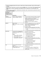
... There is lit, replace the fan. 4. (Trained service technician only) Replace the system board. Reseat the Remote Supervisor Adapter II SlimLine. 2. then, press the light path diagnostics button on the DIMM to be performed only by "(Trained service technician only)," that has ...Adapter II SlimLine (see the Problem Determination and Service Guide on the IBM System x Documentation CD to determine which components are customer replaceable units (CRU) and which they are field replaceable units (FRU). SAS signal and power cables d. Note: A failing fan can also cause 2. Reseat the...
... There is lit, replace the fan. 4. (Trained service technician only) Replace the system board. Reseat the Remote Supervisor Adapter II SlimLine. 2. then, press the light path diagnostics button on the DIMM to be performed only by "(Trained service technician only)," that has ...Adapter II SlimLine (see the Problem Determination and Service Guide on the IBM System x Documentation CD to determine which components are customer replaceable units (CRU) and which they are field replaceable units (FRU). SAS signal and power cables d. Note: A failing fan can also cause 2. Reseat the...
Installation Guide
Page 119
...Class A electronic emission notice 102 command-line interface commands identify 53 power 53 sel 53 sysinfo 53 for remote management 53 components 6 configuration... removing 11 CPU LED 92 custom configuration, ServeRAID Manager 57 © Copyright IBM Corp. 2008 D danger statements 4 DASD LED 93 data rate, Ethernet 61... hot-swap 24 drives 5 DVD drive activity LED 36 drive problems 77 eject button 36 E electrical input 5 electronic emission Class A notice 102 EMC shield, hard...optional devices 85 pointing device, non-USB 80 power 86 serial port 87 ServerGuide 88 software 89 USB port 89...
...Class A electronic emission notice 102 command-line interface commands identify 53 power 53 sel 53 sysinfo 53 for remote management 53 components 6 configuration... removing 11 CPU LED 92 custom configuration, ServeRAID Manager 57 © Copyright IBM Corp. 2008 D danger statements 4 DASD LED 93 data rate, Ethernet 61... hot-swap 24 drives 5 DVD drive activity LED 36 drive problems 77 eject button 36 E electrical input 5 electronic emission Class A notice 102 EMC shield, hard...optional devices 85 pointing device, non-USB 80 power 86 serial port 87 ServerGuide 88 software 89 USB port 89...
Installation Guide
Page 120
... power and cooling option 19 VRM 26 integrated functions 5 system management microprocessor firmware, updating 42 intermittent problems 79 ISMP firmware, updating 42 K keyboard connector 37 problems 80 keys 2 L LEDs front of server 35 rear of server 37 LEDs, light path CPU 92 DASD 93 FAN 93 MEM 93 NMI 94 106 IBM System x3500 Type 7977... configuring 43 installing 51 P parallel connector 37 PCI BRD LED 94 slot 1 27 slot 6 27 slots 2 and 3 27 slots 4 and 5 27 POST error messages 64 power control button 35 control button shield 35 cord connector 37 LED 35...
... power and cooling option 19 VRM 26 integrated functions 5 system management microprocessor firmware, updating 42 intermittent problems 79 ISMP firmware, updating 42 K keyboard connector 37 problems 80 keys 2 L LEDs front of server 35 rear of server 37 LEDs, light path CPU 92 DASD 93 FAN 93 MEM 93 NMI 94 106 IBM System x3500 Type 7977... configuring 43 installing 51 P parallel connector 37 PCI BRD LED 94 slot 1 27 slot 6 27 slots 2 and 3 27 slots 4 and 5 27 POST error messages 64 power control button 35 control button shield 35 cord connector 37 LED 35...
User Guide
Page 12
To remove all electrical current from the device, ensure that all power cords are disconnected from the power source. 2 1 x IBM System x3500 Type 7977: User's Guide Statement 5: ≥ 55 kg (121.2 lb) CAUTION: The power control button on the device and the power switch on the power supply do not turn off the electrical current supplied to the device. Statement 4: ≥ 18 kg (39.7 lb) ≥ 32 kg (70.5 lb) CAUTION: Use safe practices when lifting. The device also might have more than one power cord.
To remove all electrical current from the device, ensure that all power cords are disconnected from the power source. 2 1 x IBM System x3500 Type 7977: User's Guide Statement 5: ≥ 55 kg (121.2 lb) CAUTION: The power control button on the device and the power switch on the power supply do not turn off the electrical current supplied to the device. Statement 4: ≥ 18 kg (39.7 lb) ≥ 32 kg (70.5 lb) CAUTION: Use safe practices when lifting. The device also might have more than one power cord.

User Guide
Page 22
...and still connected to turn the server on the IBM System x Documentation CD). 8 IBM System x3500 Type 7977: User's Guide The event is on, the server power supplies are visible. Front view The following illustration ...shows the controls and LEDs on the rear of the server. A power LED is flashing, it indicates that the drive bays are nonredundant, or some other servers. System power LED Power-control button Hard disk drive activity LED System...
...and still connected to turn the server on the IBM System x Documentation CD). 8 IBM System x3500 Type 7977: User's Guide The event is on, the server power supplies are visible. Front view The following illustration ...shows the controls and LEDs on the rear of the server. A power LED is flashing, it indicates that the drive bays are nonredundant, or some other servers. System power LED Power-control button Hard disk drive activity LED System...
User Guide
Page 25
... software can turn on the server. While the server remains connected to ac power, one or more fans might start the operating system by pressing the power-control button. Chapter 1. SlimLine to turn on the server and start running to this connector. Note: When this connector is configured ...server, you turn off the server and leave it is configured for the service processor is not turned on, the operating system does not run . The System x3500 server 11 Turning on from the service processor, such as a remote request to control the server remotely. Do not connect ...
... software can turn on the server. While the server remains connected to ac power, one or more fans might start the operating system by pressing the power-control button. Chapter 1. SlimLine to turn on the server and start running to this connector. Note: When this connector is configured ...server, you turn off the server and leave it is configured for the service processor is not turned on, the operating system does not run . The System x3500 server 11 Turning on from the service processor, such as a remote request to control the server remotely. Do not connect ...
User Guide
Page 26
... Supervisor Adapter user interface. To remove all power cords are disconnected from the power source. 2 1 The server can be turned off in the server, the server can be turned off from the service processor. 12 IBM System x3500 Type 7977: User's Guide v If an optional Remote... Supervisor Adapter is connected to start an orderly shutdown of the operating system, the server will be turned off automatically. Some operating systems require an orderly shutdown before you can press and hold the power-control button ...
... Supervisor Adapter user interface. To remove all power cords are disconnected from the power source. 2 1 The server can be turned off in the server, the server can be turned off from the service processor. 12 IBM System x3500 Type 7977: User's Guide v If an optional Remote... Supervisor Adapter is connected to start an orderly shutdown of the operating system, the server will be turned off automatically. Some operating systems require an orderly shutdown before you can press and hold the power-control button ...
User Guide
Page 30
... input/output connectors and the NMI switch on the system board. When you push the remind button, the system error LED will then stop flashing and return to solve the problems. 16 IBM System x3500 Type 7977: User's Guide If another error occurs, the system error LED will flash every 2 seconds until the ... LEDs are also visible through the left-side cover. 1 POWER SUPPLY 2 CONFIG TEMP REMIND MEMORY DASD/ RAID FAN CPU S_ERR VRM PCI BUS SP BUS NMI SEE INSIDE COVER FOR MORE SERVICE INFORMATION Use the remind button on the light path diagnostic panel to acknowledge that they indicate...
... input/output connectors and the NMI switch on the system board. When you push the remind button, the system error LED will then stop flashing and return to solve the problems. 16 IBM System x3500 Type 7977: User's Guide If another error occurs, the system error LED will flash every 2 seconds until the ... LEDs are also visible through the left-side cover. 1 POWER SUPPLY 2 CONFIG TEMP REMIND MEMORY DASD/ RAID FAN CPU S_ERR VRM PCI BUS SP BUS NMI SEE INSIDE COVER FOR MORE SERVICE INFORMATION Use the remind button on the light path diagnostic panel to acknowledge that they indicate...
User Guide
Page 33
...Adapter II SlimLine. 2. Note: The error LED on the failing hard disk drive is solved. then, press the light path diagnostics button on the IBM System x Documentation CDto determine which components are customer replaceable units (CRU) and which they are field replaceable units (FRU). Notes: 1. ...Failing hard disk drive b. SAS signal and power cables d. FAN A fan has failed or has been 1. If an individual fan LED is a ...
...Adapter II SlimLine. 2. Note: The error LED on the failing hard disk drive is solved. then, press the light path diagnostics button on the IBM System x Documentation CDto determine which components are customer replaceable units (CRU) and which they are field replaceable units (FRU). Notes: 1. ...Failing hard disk drive b. SAS signal and power cables d. FAN A fan has failed or has been 1. If an individual fan LED is a ...
User Guide
Page 36
...adequate space around the front and rear of the power-supply bays has a power-supply installed in it . v You have replaced a hot-swap drive within 48 hours. v Wear an electrostatic-discharge wrist strap, if one is available. 22 IBM System x3500 Type 7977: User's Guide Working inside the server. v ... power, each of the server. To reduce the possibility of supported optional devices for extended periods of time (more than 30 minutes) with the left -side cover before working inside the server with optional adapters. v For a list of damage from your forearms. Button...
...adequate space around the front and rear of the power-supply bays has a power-supply installed in it . v You have replaced a hot-swap drive within 48 hours. v Wear an electrostatic-discharge wrist strap, if one is available. 22 IBM System x3500 Type 7977: User's Guide Working inside the server. v ... power, each of the server. To reduce the possibility of supported optional devices for extended periods of time (more than 30 minutes) with the left -side cover before working inside the server with optional adapters. v For a list of damage from your forearms. Button...
User Guide
Page 99
... electronic emission notice 81 command-line interface commands identify 68 power 68 sel 68 sysinfo 68 for remote management 68 completing... with ServerGuide 56 configuring RAID controller 72 © Copyright IBM Corp. 2007 configuring (continued) SAS devices 72 connecting the...danger statements 2 DASD LED 19 data rate, Ethernet 70 Device Driver and IBM Enhanced Diagnostics CD 4 device drivers 7 diagnostics CD 4 dimensions 3 DIMM installation... 33 drives 3, 4 DVD drive 27 DVD drive activity LED 9 DVD-eject button 9 E electrical input 3 electronic emission Class A notice 81 enabling Broadcom Gigabit ...
... electronic emission notice 81 command-line interface commands identify 68 power 68 sel 68 sysinfo 68 for remote management 68 completing... with ServerGuide 56 configuring RAID controller 72 © Copyright IBM Corp. 2007 configuring (continued) SAS devices 72 connecting the...danger statements 2 DASD LED 19 data rate, Ethernet 70 Device Driver and IBM Enhanced Diagnostics CD 4 device drivers 7 diagnostics CD 4 dimensions 3 DIMM installation... 33 drives 3, 4 DVD drive 27 DVD drive activity LED 9 DVD-eject button 9 E electrical input 3 electronic emission Class A notice 81 enabling Broadcom Gigabit ...
User Guide
Page 101
... BRD LED 19 peripheral component interconnect (PCI) configuration 52 ports enabling 51 power LED 8 power requirement 3 power supply 3 power-control button 8 power-control-button shield 8 power-cord connector 10 power-on password 54 power-on self-test (POST) error log 53 processor control 52 product recycling ...password See administrator password symmetric multiprocessing 5 system board external connectors 16 internal connectors 14 LEDs 15 system event/error log 53 system locator LED 8 system reliability guidelines 22 system-error LED 9 system-information LED 8 systems management 5, 6 T TEMP LED ...
... BRD LED 19 peripheral component interconnect (PCI) configuration 52 ports enabling 51 power LED 8 power requirement 3 power supply 3 power-control button 8 power-control-button shield 8 power-cord connector 10 power-on password 54 power-on self-test (POST) error log 53 processor control 52 product recycling ...password See administrator password symmetric multiprocessing 5 system board external connectors 16 internal connectors 14 LEDs 15 system event/error log 53 system locator LED 8 system reliability guidelines 22 system-error LED 9 system-information LED 8 systems management 5, 6 T TEMP LED ...


