
Service Guide
Page 4
... Panel Display 6-44 Operator Panel Control Assembly 6-45 Serial/Parallel Card 6-46 iv Service Guide System Management Services 5-1 Graphical System Management Services 5-1 Config 5-5 MultiBoot 5-7 Utilities 5-10 Password 5-12 Error Log 5-16 RIPL 5-17 SCSI ID 5-21 Update 5-22 Text-Based System Management Services 5-24 Chapter 6. Physical Location Codes AIX and Physical Location Code Reference Table...
... Panel Display 6-44 Operator Panel Control Assembly 6-45 Serial/Parallel Card 6-46 iv Service Guide System Management Services 5-1 Graphical System Management Services 5-1 Config 5-5 MultiBoot 5-7 Utilities 5-10 Password 5-12 Error Log 5-16 RIPL 5-17 SCSI ID 5-21 Update 5-22 Text-Based System Management Services 5-24 Chapter 6. Physical Location Codes AIX and Physical Location Code Reference Table...

Service Guide
Page 8
viii Service Guide The limits for Class B equipment were derived for typical residential environments to electromagnetic compatibility. Canadian Department of Communications Compliance Statement This Class A digital apparatus meets ...
viii Service Guide The limits for Class B equipment were derived for typical residential environments to electromagnetic compatibility. Canadian Department of Communications Compliance Statement This Class A digital apparatus meets ...
Service Guide
Page 10
... standard of option cards supplied by Information Technology Equipment (VCCI). In a domestic environment this equipment is used in the box above. This is a Class A product. x Service Guide The manufacturer cannot accept responsibility for Class A Information Technology Equipment according to take corrective actions.
... standard of option cards supplied by Information Technology Equipment (VCCI). In a domestic environment this equipment is used in the box above. This is a Class A product. x Service Guide The manufacturer cannot accept responsibility for Class A Information Technology Equipment according to take corrective actions.

Service Guide
Page 12
DANGER To prevent electrical shock hazard, disconnect the power cable from the electrical outlet before relocating the system. xii Service Guide
DANGER To prevent electrical shock hazard, disconnect the power cable from the electrical outlet before relocating the system. xii Service Guide
Service Guide
Page 26
... firmware code hands off control to boot from the devices listed in the range from 05XX to 80% noncondensing Maximum Altitude - 2135 m (7000 feet) 1-10 Service Guide Specifications The mechanical packaging, cooling, power supply, and environmental requirements for the server is E1XX. 8. LCD Code range is shown in the following: Dimensions Height...
... firmware code hands off control to boot from the devices listed in the range from 05XX to 80% noncondensing Maximum Altitude - 2135 m (7000 feet) 1-10 Service Guide Specifications The mechanical packaging, cooling, power supply, and environmental requirements for the server is E1XX. 8. LCD Code range is shown in the following: Dimensions Height...
Service Guide
Page 28
... 15 feet in other countries consist of U.S.): use a cable set should have the appropriate safety approvals for the specific countries where they are available. 1-12 Service Guide Attachment plugs approved by the Canadian Standards Association (CSA). The cable set consisting of 15 feet in the United States use a UL listed cable set...
... 15 feet in other countries consist of U.S.): use a cable set should have the appropriate safety approvals for the specific countries where they are available. 1-12 Service Guide Attachment plugs approved by the Canadian Standards Association (CSA). The cable set consisting of 15 feet in the United States use a UL listed cable set...

Service Guide
Page 30
With the external power cable connected to the device, check for the correct grounded power cable. Check for 0.1 ohm or less resistance between the ground lug on the external power cable the metal frame of the device. 13. Install the covers. 1-14 Service Guide c. b.
With the external power cable connected to the device, check for the correct grounded power cable. Check for 0.1 ohm or less resistance between the ground lug on the external power cable the metal frame of the device. 13. Install the covers. 1-14 Service Guide c. b.

Service Guide
Page 32
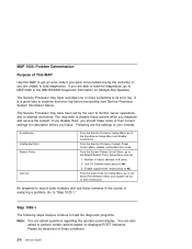
...(graphic display) or device mnemonics (ASCII terminal) that appear during the power-on a graphics terminal. 2-2 Service Guide The term "POST indicators" refer to the Fast Path MAP in the IBM RS/6000 Diagnostic Information for power on page 3-1. Go to "MAP 1020: Problem Determination" on page 3-... message "STARTING SOFTWARE PLEASE WAIT..." The system is waiting for Multiple Bus Systems. Action Symptom Analysis You have OK displayed The Service Processor (SP) is ready. This condition can be requested by the operating system and is ready. You have an SRN. ...
...(graphic display) or device mnemonics (ASCII terminal) that appear during the power-on a graphics terminal. 2-2 Service Guide The term "POST indicators" refer to the Fast Path MAP in the IBM RS/6000 Diagnostic Information for power on page 3-1. Go to "MAP 1020: Problem Determination" on page 3-... message "STARTING SOFTWARE PLEASE WAIT..." The system is waiting for Multiple Bus Systems. Action Symptom Analysis You have OK displayed The Service Processor (SP) is ready. This condition can be requested by the operating system and is ready. You have an SRN. ...

Service Guide
Page 34
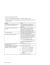
...or stay on page 2-12. No codes are actually attached. You have a problem that ID. Go to the Fast Path MAP in the IBM RS/6000 Diagnostic Information for Multiple Bus Systems. Note: If the operator panel displays 2 sets of numbers, use the same SCSI bus ID ... controller or adapter with the character "E0xx" then go to the Fast Path MAP in the IBM RS/6000 Diagnostic Information for Multiple Bus Systems. 2-4 Service Guide Action If the number displayed begins with the System Management Services. I/O planar (See notes on 2-1 if the I /O planar if connected to "MAP 1020: ...
...or stay on page 2-12. No codes are actually attached. You have a problem that ID. Go to the Fast Path MAP in the IBM RS/6000 Diagnostic Information for Multiple Bus Systems. Note: If the operator panel displays 2 sets of numbers, use the same SCSI bus ID ... controller or adapter with the character "E0xx" then go to the Fast Path MAP in the IBM RS/6000 Diagnostic Information for Multiple Bus Systems. 2-4 Service Guide Action If the number displayed begins with the System Management Services. I/O planar (See notes on 2-1 if the I /O planar if connected to "MAP 1020: ...
Service Guide
Page 36
...Please be observant of your interest. You may wish to disable these conditions. 2-6 Service Guide If you disable them, you should make notes of their current settings for Multiple Bus Systems. The Service Processor may have recorded one by the user to monitor server operations and to ... of these actions while you leave. From the System Power Control Menu, go to MAP 0020 in the IBM RS/6000 Diagnostic Information for restoration before proceeding (see Service Processor System Information Menu). Number of analyzing a problem. Step 1020-1 The following steps analyze a failure to...
...Please be observant of your interest. You may wish to disable these conditions. 2-6 Service Guide If you disable them, you should make notes of their current settings for Multiple Bus Systems. The Service Processor may have recorded one by the user to monitor server operations and to ... of these actions while you leave. From the System Power Control Menu, go to MAP 0020 in the IBM RS/6000 Diagnostic Information for restoration before proceeding (see Service Processor System Information Menu). Number of analyzing a problem. Step 1020-1 The following steps analyze a failure to...
Service Guide
Page 38
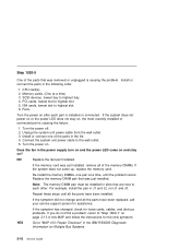
... entered. The system login prompt is entered. Enter the password. Go to continue until the diagnostics are not allowed to "Step 1020-2" on page 2-10. 2-8 Service Guide network, record error code M0NET000. The diagnostics loaded. See "Firmware Recovery" on the operator panel. If the POST indicator represents: memory, record error code M0MEM002... to occur. Action The flash EPROM data is corrupted. When you have pressed the key soon enough when you pressed the correct key in the IBM RS/6000 Diagnostic Information for the flash EPROM should be executed. 5.
... entered. The system login prompt is entered. Enter the password. Go to continue until the diagnostics are not allowed to "Step 1020-2" on page 2-10. 2-8 Service Guide network, record error code M0NET000. The diagnostics loaded. See "Firmware Recovery" on the operator panel. If the POST indicator represents: memory, record error code M0MEM002... to occur. Action The flash EPROM data is corrupted. When you have pressed the key soon enough when you pressed the correct key in the IBM RS/6000 Diagnostic Information for the flash EPROM should be executed. 5.
Service Guide
Page 40
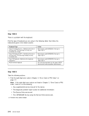
...by using in the Action column. Go to "Step 1020-3." Step 1020-3 Take the following table; Perform the action listed. 2-10 Service Guide Find the type of ASCII terminal and continue problem determination. Record error code M0KBD003; Type 102 keyboard (W.T.). then follow the instructions given ... go to FRU Index," look for it in the following: Any supplemental service manual for the device The diagnostic problem report screen for this type of keyboard you are using the Service Hints service aid). 2. Record error code M0KBD002; then go to the documentation for...
...by using in the Action column. Go to "Step 1020-3." Step 1020-3 Take the following table; Perform the action listed. 2-10 Service Guide Find the type of ASCII terminal and continue problem determination. Record error code M0KBD003; Type 102 keyboard (W.T.). then follow the instructions given ... go to FRU Index," look for it in the following: Any supplemental service manual for the device The diagnostic problem report screen for this type of keyboard you are using the Service Hints service aid). 2. Record error code M0KBD002; then go to the documentation for...

Service Guide
Page 42
Use this Power MAP only if you have been directed here from a MAP step in the IBM RS/6000 Diagnostic Information for Multiple Bus Systems. This procedure is correctly wired and grounded to prevent and electrical shock. If possible, disconnect all... hazard, disconnect the power cable from touching two surfaces with a properly grounded electrical outlet to or from the existing system before relocating the system. 2-12 Service Guide DANGER An electrical outlet that attach to a failing unit. If a problem is not correctly wired could place hazardous voltage on hand, when possible, to...
Use this Power MAP only if you have been directed here from a MAP step in the IBM RS/6000 Diagnostic Information for Multiple Bus Systems. This procedure is correctly wired and grounded to prevent and electrical shock. If possible, disconnect all... hazard, disconnect the power cable from touching two surfaces with a properly grounded electrical outlet to or from the existing system before relocating the system. 2-12 Service Guide DANGER An electrical outlet that attach to a failing unit. If a problem is not correctly wired could place hazardous voltage on hand, when possible, to...

Service Guide
Page 44
Step 1520-3 Note: Either the cooling fans, the power supply, the I /O planar Service Processor System card Front cooling fans (one of the FRUs in the list. 4. Turn the power on ? Repeat this step until the defective FRU is ... the FRUs have been exchanged, go to the wall outlet. 5. Power supply I /O planar, service processor, or the system card is connected to "MAP 410: Repair Checkout" in the IBM RS/6000 Diagnostic Information for Multiple Bus Systems. 2-14 Service Guide Unplug the system unit power cable from the wall outlet. 3. Turn the power off...
Step 1520-3 Note: Either the cooling fans, the power supply, the I /O planar Service Processor System card Front cooling fans (one of the FRUs in the list. 4. Turn the power on ? Repeat this step until the defective FRU is ... the FRUs have been exchanged, go to the wall outlet. 5. Power supply I /O planar, service processor, or the system card is connected to "MAP 410: Repair Checkout" in the IBM RS/6000 Diagnostic Information for Multiple Bus Systems. 2-14 Service Guide Unplug the system unit power cable from the wall outlet. 3. Turn the power off...
Service Guide
Page 46
... the pair in slots that are next to each part is installed or connected. If the symptom has changed, check for Multiple Bus Systems. 2-16 Service Guide Turn the power on ? Does the fan in the power supply turn on and the power LED come up, replace the memory card. If the...) 3. Replace the memory DIMM pair that was just installed. Step 1520-5 One of the parts in the list. 4. Install or connect the parts in the IBM RS/6000 Diagnostic Information for loose cards, cables, and obvious problems. If you do not find a problem, return to "MAP 410: Repair Checkout" in the...
... the pair in slots that are next to each part is installed or connected. If the symptom has changed, check for Multiple Bus Systems. 2-16 Service Guide Turn the power on ? Does the fan in the power supply turn on and the power LED come up, replace the memory card. If the...) 3. Replace the memory DIMM pair that was just installed. Step 1520-5 One of the parts in the list. 4. Install or connect the parts in the IBM RS/6000 Diagnostic Information for loose cards, cables, and obvious problems. If you do not find a problem, return to "MAP 410: Repair Checkout" in the...
Service Guide
Page 48
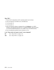
... the appropriate password when prompted to "Step 1540-12" on page 2-19. Turn the power off. 4. NO Go to "Step 1540-2" on page 2-31. 2-18 Service Guide Is the "Please define the System Console" screen displayed? YES Go to do so. Ensure that the diagnostics and the operating system are shut down...
... the appropriate password when prompted to "Step 1540-12" on page 2-19. Turn the power off. 4. NO Go to "Step 1540-2" on page 2-31. 2-18 Service Guide Is the "Please define the System Console" screen displayed? YES Go to do so. Ensure that the diagnostics and the operating system are shut down...

Service Guide
Page 50
...or all the FRUs have been exchanged. Turn the power off, remove the power cable, and exchange the following steps call your service support person for Multiple Bus Systems. 2-20 Service Guide System Card 6. Other checkpoints may take up to 3 minutes to assure stability, depending on page 2-18 in this MAP and ... 1540-1" on system configuration. Does the operator panel stabilize with code E1F2, E1F3, E1F7, or STBY? Processor cards 2. If the following FRUs in the IBM RS/6000 Diagnostic Information for assistance. Service Processor Wait for a I /O planar (see notes on page 2-1.) 5.
...or all the FRUs have been exchanged. Turn the power off, remove the power cable, and exchange the following steps call your service support person for Multiple Bus Systems. 2-20 Service Guide System Card 6. Other checkpoints may take up to 3 minutes to assure stability, depending on page 2-18 in this MAP and ... 1540-1" on system configuration. Does the operator panel stabilize with code E1F2, E1F3, E1F7, or STBY? Processor cards 2. If the following FRUs in the IBM RS/6000 Diagnostic Information for assistance. Service Processor Wait for a I /O planar (see notes on page 2-1.) 5.

Service Guide
Page 52
Reinstall the power cable. 4. Wait for the operator panel to "MAP 410: Repair Checkout" in the IBM RS/6000 Diagnostic Information for Multiple Bus Systems. 2-22 Service Guide YES Go to stabilize at a checkpoint. Exchange the last memory DIMM pair installed. 3. Does the operator panel stabilize with code E1F2, E1F3, E1F7, or STBY? ...
Reinstall the power cable. 4. Wait for the operator panel to "MAP 410: Repair Checkout" in the IBM RS/6000 Diagnostic Information for Multiple Bus Systems. 2-22 Service Guide YES Go to stabilize at a checkpoint. Exchange the last memory DIMM pair installed. 3. Does the operator panel stabilize with code E1F2, E1F3, E1F7, or STBY? ...

Service Guide
Page 54
b. When the keyboard indicator is displayed or the system appears to stop. 2-24 Service Guide Notes: a. This triggers the SMS. 6. Reconnect the system console. Plug the keyboard into the keyboard connector on an ASCII terminal. Enter the appropriate password when ...
b. When the keyboard indicator is displayed or the system appears to stop. 2-24 Service Guide Notes: a. This triggers the SMS. 6. Reconnect the system console. Plug the keyboard into the keyboard connector on an ASCII terminal. Enter the appropriate password when ...
Service Guide
Page 56
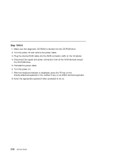
After the keyboard indicator is inserted into the SCSI connector (J25) on the I/O planar. 4. Enter the appropriate password when prompted to do so. 2-26 Service Guide Turn the power on an ASCII terminal keyboard. 8. Turn the power off and remove the power cable. 3. Plug the internal SCSI cable into the CD-...
After the keyboard indicator is inserted into the SCSI connector (J25) on the I/O planar. 4. Enter the appropriate password when prompted to do so. 2-26 Service Guide Turn the power on an ASCII terminal keyboard. 8. Turn the power off and remove the power cable. 3. Plug the internal SCSI cable into the CD-...


