
Installation Guide
Page 5
... Toroid 6 Step 10. Need Help 3 Step 3. Connect the Keyboard and Mouse (When Using a Graphics Display 8 Step 12. Connect the Serial Devices, Parallel Devices, and ASCII Terminal 9 Step 13. Check Your Inventory 1 IntelliStation POWER 9114 Model 275 1 Step 2. Adjust the Stability Feet 5 Step 8. Check Your Display or Console Type 5 Step 9. Your System Hardware is Now Set...
... Toroid 6 Step 10. Need Help 3 Step 3. Connect the Keyboard and Mouse (When Using a Graphics Display 8 Step 12. Connect the Serial Devices, Parallel Devices, and ASCII Terminal 9 Step 13. Check Your Inventory 1 IntelliStation POWER 9114 Model 275 1 Step 2. Adjust the Stability Feet 5 Step 8. Check Your Display or Console Type 5 Step 9. Your System Hardware is Now Set...

Installation Guide
Page 17
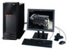
Check Your Inventory IntelliStation POWER 9114 Model 275 h Books, CD-ROM and Other Media h ″About Your Machine″ Document h Power Cables (1 standard, 2 optional) h 9-Pin to 25-Pin Serial Converters (2) (optional) h ASCII Terminal (optional) 1 Step 1. Chapter 1. Setting Up the System To set up your system, follow the procedures in this chapter.
Check Your Inventory IntelliStation POWER 9114 Model 275 h Books, CD-ROM and Other Media h ″About Your Machine″ Document h Power Cables (1 standard, 2 optional) h 9-Pin to 25-Pin Serial Converters (2) (optional) h ASCII Terminal (optional) 1 Step 1. Chapter 1. Setting Up the System To set up your system, follow the procedures in this chapter.

Installation Guide
Page 21
Connect the Serial Devices, Parallel Devices, and ASCII Terminal" on page 6. If you want to: v Attach another display to your system unit OR v Change the default display resolution ...
Connect the Serial Devices, Parallel Devices, and ASCII Terminal" on page 6. If you want to: v Attach another display to your system unit OR v Change the default display resolution ...

Installation Guide
Page 23
Connect the Serial Devices, Parallel Devices, and ASCII Terminal" on page 6, connect the graphics display cable to the back of the display and to connect, continue with the ...
Connect the Serial Devices, Parallel Devices, and ASCII Terminal" on page 6, connect the graphics display cable to the back of the display and to connect, continue with the ...

Installation Guide
Page 25
... the rear of the system. You can connect additional serial devices to 25-pin serial converter cable. If you have a local ASCII terminal or a single serial device, connect it to serial connector S2 or serial connector S3. The 9-pin to the parallel connector. 1 Serial Port 1 Connector 2 Serial Port 2 Connector 3 Serial Port 3 Connector 4 Parallel Connector Chapter 1. If you have...
... the rear of the system. You can connect additional serial devices to 25-pin serial converter cable. If you have a local ASCII terminal or a single serial device, connect it to serial connector S2 or serial connector S3. The 9-pin to the parallel connector. 1 Serial Port 1 Connector 2 Serial Port 2 Connector 3 Serial Port 3 Connector 4 Parallel Connector Chapter 1. If you have...

Installation Guide
Page 26
... using any optional adapters (such as follows: Serial Port Number Serial Port 1 (S1 Rear) Location Rear of the System Serial Port 2 (S2) Rear of the System Serial Port 3 (S3) Rear of the System Examples of installed adapters, consult the ″About Your Machine″ document. 10 IntelliStation POWER 9114 Model 275 Installation Guide For the locations of Applicable...
... using any optional adapters (such as follows: Serial Port Number Serial Port 1 (S1 Rear) Location Rear of the System Serial Port 2 (S2) Rear of the System Serial Port 3 (S3) Rear of the System Examples of installed adapters, consult the ″About Your Machine″ document. 10 IntelliStation POWER 9114 Model 275 Installation Guide For the locations of Applicable...
Installation Guide
Page 30
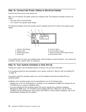
...operating system, AIX can be installed from a NIM server, see the installation instructions provided with the software. 14 IntelliStation POWER 9114 Model 275 Installation Guide Step 19. Installation of the operating system can use them comfortably. For information about installing AIX from ...2 Attention LED 3 System Reset Button 4 Power LED 5 Power-On Button 6 Power-On Button Guard 7 Service Processor Reset Switch (Pinhole) 8 Serial Number Label If your operating system. Connect the Power Cables to Electrical Outlets Connect the power source to install the operating system now, ...
...operating system, AIX can be installed from a NIM server, see the installation instructions provided with the software. 14 IntelliStation POWER 9114 Model 275 Installation Guide Step 19. Installation of the operating system can use them comfortably. For information about installing AIX from ...2 Attention LED 3 System Reset Button 4 Power LED 5 Power-On Button 6 Power-On Button Guard 7 Service Processor Reset Switch (Pinhole) 8 Serial Number Label If your operating system. Connect the Power Cables to Electrical Outlets Connect the power source to install the operating system now, ...

Installation Guide
Page 31
.... 1 Operator Panel Display 2 Front Serial Connector (FS1) 3 Attention LED 4 System Reset Button 5 Power LED 6 Power-On Button 7 Power-On Guard 8 Service Processor Reset Switch (Pinhole) 9 Serial Number Label 3. Setting Up the System 15 Step 20. Before you press the power-on button located on solid (no longer blinking). Start Your Model 275 To power on your operator panel...
.... 1 Operator Panel Display 2 Front Serial Connector (FS1) 3 Attention LED 4 System Reset Button 5 Power LED 6 Power-On Button 7 Power-On Guard 8 Service Processor Reset Switch (Pinhole) 9 Serial Number Label 3. Setting Up the System 15 Step 20. Before you press the power-on button located on solid (no longer blinking). Start Your Model 275 To power on your operator panel...

Installation Guide
Page 41
... the system as checkpoints, are visible on the operator panel display. 1 Operator Panel Display 2 Attention LED 3 System Reset Button 4 Power LED 5 Power-On Button 6 Power-On Button Guard 7 Service Processor Reset Switch (Pinhole) 8 Serial Number Label Chapter 3. The system cooling fans are activated after a short interval and can result in this chapter will direct...
... the system as checkpoints, are visible on the operator panel display. 1 Operator Panel Display 2 Attention LED 3 System Reset Button 4 Power LED 5 Power-On Button 6 Power-On Button Guard 7 Service Processor Reset Switch (Pinhole) 8 Serial Number Label Chapter 3. The system cooling fans are activated after a short interval and can result in this chapter will direct...

Installation Guide
Page 85
Appendix D. Identification Numbers Record and retain the following information: Product Name IntelliStation POWER 9114 Model 275 Serial Number Key Serial Number The system unit's serial numbers are located on the front of the system's identification information. System Records Use this appendix to keep a record of the machine, as shown in the following illustration: 69
Appendix D. Identification Numbers Record and retain the following information: Product Name IntelliStation POWER 9114 Model 275 Serial Number Key Serial Number The system unit's serial numbers are located on the front of the system's identification information. System Records Use this appendix to keep a record of the machine, as shown in the following illustration: 69

Installation Guide
Page 87
Options Location Mouse Connector Keyboard Connector Expansion Slot 6 Expansion Slot 5 Expansion Slot 4 Expansion Slot 3 Expansion Slot 2 Expansion Slot 1 Parallel Port Serial Port 1 Serial Port 2 Serial Port 3 Ethernet 1 Ethernet 2 Option Description IBM Mouse h Other Space Saving h Enhanced h Other Appendix D. System Records 71
Options Location Mouse Connector Keyboard Connector Expansion Slot 6 Expansion Slot 5 Expansion Slot 4 Expansion Slot 3 Expansion Slot 2 Expansion Slot 1 Parallel Port Serial Port 1 Serial Port 2 Serial Port 3 Ethernet 1 Ethernet 2 Option Description IBM Mouse h Other Space Saving h Enhanced h Other Appendix D. System Records 71

Installation Guide
Page 95
...statement ix ergonomic information xiv Ethernet connection 11 B battery 59 disposal, recycling 65 bezels (Model 275) 27 removal 27 C checklist, inventory 1 configuration client 19 NIM server 19 connect internal ethernet ...11 connecting adapter cables 10 graphics display 7 keyboard and mouse 8 serial and parallel devices 9 console, display type 5 covers 28 removal 28 replacement 28 D deconfiguring disk... information, accessing xiii installing acoustical cover 13 power-on button guard 13 stability feet 5 installing options 25 starting the system 15, 25 stopping ...
...statement ix ergonomic information xiv Ethernet connection 11 B battery 59 disposal, recycling 65 bezels (Model 275) 27 removal 27 C checklist, inventory 1 configuration client 19 NIM server 19 connect internal ethernet ...11 connecting adapter cables 10 graphics display 7 keyboard and mouse 8 serial and parallel devices 9 console, display type 5 covers 28 removal 28 replacement 28 D deconfiguring disk... information, accessing xiii installing acoustical cover 13 power-on button guard 13 stability feet 5 installing options 25 starting the system 15, 25 stopping ...

Installation Guide
Page 96
... 23 front door 26 service access cover 28 static-sensitive devices 24 removal and replacement procedures 23 access cover removal 28 80 IntelliStation POWER 9114 Model 275 Installation Guide removal and replacement procedures (continued) adapter removal, non-hot-plug 29 adapter, adding or replacing a non-hot-... disk drives 51 media drives 43 service access cover 28 S safety notices vii, 3 SCSI drives 43 SCSI Media Devices power cable 43 SCSI cable 43 serial and parallel devices connection 9 setting up the system 1 setup, complete 14 stability feet installing 5 standalone diagnostics NIM server ...
... 23 front door 26 service access cover 28 static-sensitive devices 24 removal and replacement procedures 23 access cover removal 28 80 IntelliStation POWER 9114 Model 275 Installation Guide removal and replacement procedures (continued) adapter removal, non-hot-plug 29 adapter, adding or replacing a non-hot-... disk drives 51 media drives 43 service access cover 28 S safety notices vii, 3 SCSI drives 43 SCSI Media Devices power cable 43 SCSI cable 43 serial and parallel devices connection 9 setting up the system 1 setup, complete 14 stability feet installing 5 standalone diagnostics NIM server ...

Service Guide
Page 7
...Menu 196 Service Processor Setup Menu 197 Passwords 198 System Power Control Menu 202 System Information Menu 205 Language Selection Menu 210 Call-In/Call-Out Setup Menu 211 Modem Configuration Menu 212 Serial Port Selection Menu 212 Serial Port Speed Setup Menu 213 Telephone Number Setup Menu ...213 Call-Out Policy Setup Menu 214 Customer Account Setup Menu 215 Call-out Test Menu 215 Service Processor Parameters in Service Mode 215 System Power-On Methods 215 ...
...Menu 196 Service Processor Setup Menu 197 Passwords 198 System Power Control Menu 202 System Information Menu 205 Language Selection Menu 210 Call-In/Call-Out Setup Menu 211 Modem Configuration Menu 212 Serial Port Selection Menu 212 Serial Port Speed Setup Menu 213 Telephone Number Setup Menu ...213 Call-Out Policy Setup Menu 214 Customer Account Setup Menu 215 Call-out Test Menu 215 Service Processor Parameters in Service Mode 215 System Power-On Methods 215 ...

Service Guide
Page 10
... 315 Testing the Setup 316 Testing Call-In 316 Testing Call-Out 316 Serial Port Configuration 317 Appendix D. Notices 313 Appendix C. Modem Configurations 323 Sample ...Using the Generic Sample Modem Configuration Files 325 Customizing the Modem Configuration Files 326 IBM 7852-400 DIP Switch Settings 327 Xon/Xoff Modems 327 Ring Detection 328 Terminal... 342 Sample File modem_f0.cfg 344 Sample File modem_f1.cfg 346 Index 349 viii IntelliStation POWER 9114 Model 275 Service Guide General Attributes Required When Using a TTY Terminal 319 Additional Communication Attributes...
... 315 Testing the Setup 316 Testing Call-In 316 Testing Call-Out 316 Serial Port Configuration 317 Appendix D. Notices 313 Appendix C. Modem Configurations 323 Sample ...Using the Generic Sample Modem Configuration Files 325 Customizing the Modem Configuration Files 326 IBM 7852-400 DIP Switch Settings 327 Xon/Xoff Modems 327 Ring Detection 328 Terminal... 342 Sample File modem_f0.cfg 344 Sample File modem_f1.cfg 346 Index 349 viii IntelliStation POWER 9114 Model 275 Service Guide General Attributes Required When Using a TTY Terminal 319 Additional Communication Attributes...

Service Guide
Page 22
...: 1. Do not run HACMP with a UPS attached, you are as follows: Serial Port Number Serial Port 1 (S1 Rear) Location Rear of the System Serial Port 2 (S2) Rear of the System Serial Port 3 (S3) Rear of the System Examples of the serial ports. 4 IntelliStation POWER 9114 Model 275 Service Guide If you decide to disconnect HACMP, you must connect the...
...: 1. Do not run HACMP with a UPS attached, you are as follows: Serial Port Number Serial Port 1 (S1 Rear) Location Rear of the System Serial Port 2 (S2) Rear of the System Serial Port 3 (S3) Rear of the System Examples of the serial ports. 4 IntelliStation POWER 9114 Model 275 Service Guide If you decide to disconnect HACMP, you must connect the...

Service Guide
Page 23
...: v After OK displays in the operator panel AND v Before the power-on sequence is selected as previously described), or the contents of the available console devices. Note: Moving an ASCII terminal from one serial port to another PCI slot). Chapter 1. Set from the service processor ... to power on page 247. The next section describes the POST indicators and functions that the hardware is functioning correctly before the operating system is loaded. v A change in the system configuration (as the console and the selection sequence times out. Security Features The Model 275 allows ...
...: v After OK displays in the operator panel AND v Before the power-on sequence is selected as previously described), or the contents of the available console devices. Note: Moving an ASCII terminal from one serial port to another PCI slot). Chapter 1. Set from the service processor ... to power on page 247. The next section describes the POST indicators and functions that the hardware is functioning correctly before the operating system is loaded. v A change in the system configuration (as the console and the selection sequence times out. Security Features The Model 275 allows ...

Service Guide
Page 26
Rear View 15 14 13 12 11 10 9 8 7 1 Parallel Connector 2 Keyboard 3 Serial Connector 2 4 Serial Connector 3 5 Test Connector (For Manufacturing Use Only) 6 Serial Connector 1 7 PCI-X Slot Access 8 Rack Indicator 1 2 3 4 5 6 9 Mouse 10 1 Gb Ethernet Connector 11 10/100 Gb Ethernet Connector 12 Reserved 13 Reserved 14 Primary Power Supply V2 Receptacle 15 Redundant Power Supply V1 Receptacle 8 IntelliStation POWER 9114 Model 275 Service Guide
Rear View 15 14 13 12 11 10 9 8 7 1 Parallel Connector 2 Keyboard 3 Serial Connector 2 4 Serial Connector 3 5 Test Connector (For Manufacturing Use Only) 6 Serial Connector 1 7 PCI-X Slot Access 8 Rack Indicator 1 2 3 4 5 6 9 Mouse 10 1 Gb Ethernet Connector 11 10/100 Gb Ethernet Connector 12 Reserved 13 Reserved 14 Primary Power Supply V2 Receptacle 15 Redundant Power Supply V1 Receptacle 8 IntelliStation POWER 9114 Model 275 Service Guide

Service Guide
Page 33
... solid. Normal State - Number 1 2 3 4 5 6 7 8 Component Name Operator Panel Display Attention LED System Reset Button Power LED Power-On Button Power-On Button Guard Service Processor Reset Switch (Pinhole) Serial Number Label Component Description Displays current status of a hardware problem. LED is in the event of system startup, or diagnostic information in standby mode). During...
... solid. Normal State - Number 1 2 3 4 5 6 7 8 Component Name Operator Panel Display Attention LED System Reset Button Power LED Power-On Button Power-On Button Guard Service Processor Reset Switch (Pinhole) Serial Number Label Component Description Displays current status of a hardware problem. LED is in the event of system startup, or diagnostic information in standby mode). During...

Service Guide
Page 37
...EF-G,H Non-SCSI Devices/Drives For planars, cards, and non-SCSI devices, the location code is hierarchical; The series is defined as serial port 1, but physical location codes might display in conjunction with AIX location codes to provide mapping of the AIX location codes are produced by... (M1) plugged into the system backplane P1. For example, P1-M1 is an alphanumeric string of variable length, consisting of a series of the serial port 1 controller and its connector likewise have location code P1-X1/K1, which is connected to connector K1; v The / (slash) separator character...
...EF-G,H Non-SCSI Devices/Drives For planars, cards, and non-SCSI devices, the location code is hierarchical; The series is defined as serial port 1, but physical location codes might display in conjunction with AIX location codes to provide mapping of the AIX location codes are produced by... (M1) plugged into the system backplane P1. For example, P1-M1 is an alphanumeric string of variable length, consisting of a series of the serial port 1 controller and its connector likewise have location code P1-X1/K1, which is connected to connector K1; v The / (slash) separator character...


