
Hardware Maintenance Manual
Page 3
...Overview 2 Processors (Machine Type 2158 2 Processors (Machine Type 2163 2 Memory ...3 External Ports 3 Diskette Drive 3 Hard Disk Drive 4 CD/DVD-ROM Drive 4 Multimedia 4 Power Management 4 Power Supply 4 Internal Cabling 4 Modem ...5 Monitor (Not included with some models 5 Keyboard ...5 Mouse ...6 Hardware Interfaces 6 CMOS Reset ...7 Power-On Password 8 Flash (BIOS) Update Procedure 9 BIOS-contained Model Number and Serial Number 10 BIOS Setup Utility 11 Working with the Setup Menus 11 Viewing System Information, Video Information and Model Information.. 13 Disk Drives 14...
...Overview 2 Processors (Machine Type 2158 2 Processors (Machine Type 2163 2 Memory ...3 External Ports 3 Diskette Drive 3 Hard Disk Drive 4 CD/DVD-ROM Drive 4 Multimedia 4 Power Management 4 Power Supply 4 Internal Cabling 4 Modem ...5 Monitor (Not included with some models 5 Keyboard ...5 Mouse ...6 Hardware Interfaces 6 CMOS Reset ...7 Power-On Password 8 Flash (BIOS) Update Procedure 9 BIOS-contained Model Number and Serial Number 10 BIOS Setup Utility 11 Working with the Setup Menus 11 Viewing System Information, Video Information and Model Information.. 13 Disk Drives 14...

Hardware Maintenance Manual
Page 5
... DVD-ROM Drive Rear Panel Connectors and Jumpers 125 DIMM Configurations 126 System Board Connector Pin Signals 127 Monitor Port Signals 127 Serial Port Signals 127 Parallel Port Signals 127 Mouse Port Signals 128 Keyboard Port Signals 128 Diskette Drive Cable Connector Signals 128 IDE Cable Connector Signals 129 Safety Inspection Guide 131 General Guidelines 132 Parts Catalog 133 Abbreviations 134 Assembly 1: Machine Type 2158/2163 System Unit 135 Assembly 2: Machine Type 2158/2163 Diskette, Hard Drive 138 Contents III Adapter Cards 84 Memory(DIMM 85 AMD-K6 Processor...
... DVD-ROM Drive Rear Panel Connectors and Jumpers 125 DIMM Configurations 126 System Board Connector Pin Signals 127 Monitor Port Signals 127 Serial Port Signals 127 Parallel Port Signals 127 Mouse Port Signals 128 Keyboard Port Signals 128 Diskette Drive Cable Connector Signals 128 IDE Cable Connector Signals 129 Safety Inspection Guide 131 General Guidelines 132 Parts Catalog 133 Abbreviations 134 Assembly 1: Machine Type 2158/2163 System Unit 135 Assembly 2: Machine Type 2158/2163 Diskette, Hard Drive 138 Contents III Adapter Cards 84 Memory(DIMM 85 AMD-K6 Processor...

Hardware Maintenance Manual
Page 33
...Overview 2 Processors (Machine Type 2158 2 Processors (Machine Type 2163 2 Memory ...3 External Ports 3 Diskette Drive 4 Hard Disk Drive 4 CD/DVD-ROM Drive 4 Multimedia 4 Power Management 4 Power Supply 4 Internal Cabling 5 Modem ...5 Monitor (Not included with some models 5 Keyboard ...6 Mouse ...6 Hardware Interfaces 6 CMOS Reset ...7 Power-On Password 8 Flash (BIOS) Update Procedure 9 BIOS-contained Model Number and Serial Number 10 BIOS Setup Utility 11 Working with the Setup Menus 11 Viewing System Information, Video Information and Model Information.. 13 Disk Drives 14...
...Overview 2 Processors (Machine Type 2158 2 Processors (Machine Type 2163 2 Memory ...3 External Ports 3 Diskette Drive 4 Hard Disk Drive 4 CD/DVD-ROM Drive 4 Multimedia 4 Power Management 4 Power Supply 4 Internal Cabling 5 Modem ...5 Monitor (Not included with some models 5 Keyboard ...6 Mouse ...6 Hardware Interfaces 6 CMOS Reset ...7 Power-On Password 8 Flash (BIOS) Update Procedure 9 BIOS-contained Model Number and Serial Number 10 BIOS Setup Utility 11 Working with the Setup Menus 11 Viewing System Information, Video Information and Model Information.. 13 Disk Drives 14...
Hardware Maintenance Manual
Page 40
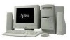
... password check process. Machine Type 2163: Set switch 5 of SW1 to the OFF position to enable password check process. Machine Type 2158: Set switch 2 of standby power when the power cord is plugged. In some cases, you might result if the power cord is entered. Select "Advanced Options", then enter "Security Options" and set password in the Setup Utility. 8 See "Machine Type 2163 System Board Jumpers and Connectors" on page 107. IMPORTANT: To reinstall the password, the user must enter a password in BIOS Setup. The system starts...
... password check process. Machine Type 2163: Set switch 5 of SW1 to the OFF position to enable password check process. Machine Type 2158: Set switch 2 of standby power when the power cord is plugged. In some cases, you might result if the power cord is entered. Select "Advanced Options", then enter "Security Options" and set password in the Setup Utility. 8 See "Machine Type 2163 System Board Jumpers and Connectors" on page 107. IMPORTANT: To reinstall the password, the user must enter a password in BIOS Setup. The system starts...
Hardware Maintenance Manual
Page 46
... drive as drive B. Enter Setup to initialize onboard VGA as the boot display device if a PCI add-on a particular IDE drive. Empty drive bays are identified as the video controller and video memory, select the video information option from the main menu. Drive B System recognizes the LS-120 drive as drive number 0 (drive A). The IDE drive items are indicated with a "None" setting. Like in the computer. Select primary display adapter to identify or verify the type of these items displays...
... drive as drive B. Enter Setup to initialize onboard VGA as the boot display device if a PCI add-on a particular IDE drive. Empty drive bays are identified as the video controller and video memory, select the video information option from the main menu. Drive B System recognizes the LS-120 drive as drive number 0 (drive A). The IDE drive items are indicated with a "None" setting. Like in the computer. Select primary display adapter to identify or verify the type of these items displays...
Hardware Maintenance Manual
Page 47
... connector 2 on the hard disk requirements. If your hard disk supports this parameter to Auto (default), Mode 0, Mode 1, Mode 2, Mode 3, or Mode 4 depending on the system board and is set as the master device. BIOS automatically detects if your hard disk does not support this function, set this parameter to Auto, change the setting to Disabled. • IDE Primary Channel Master is attached to IDE connector 1 on the system board and is set as the slave device. Hard Disk...
... connector 2 on the hard disk requirements. If your hard disk supports this parameter to Auto (default), Mode 0, Mode 1, Mode 2, Mode 3, or Mode 4 depending on the system board and is set as the master device. BIOS automatically detects if your hard disk does not support this function, set this parameter to Auto, change the setting to Disabled. • IDE Primary Channel Master is attached to IDE connector 1 on the system board and is set as the slave device. Hard Disk...
Hardware Maintenance Manual
Page 49
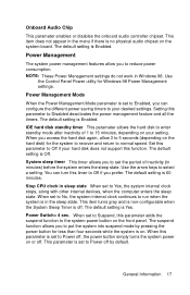
... in Windows 98. When set to run when the system is Yes. The default setting is in minutes) before the system enters the sleep state. This parameter is Enabled. The default setting is set to No, the system internal clock continues to Power off . Use the Control Panel Power utility for Windows 98 Power Management settings. IDE hard disk standby timer This parameter allows the hard disk to normal speed. System sleep timer This timer allows you access the hard disk...
... in Windows 98. When set to run when the system is Yes. The default setting is in minutes) before the system enters the sleep state. This parameter is Enabled. The default setting is set to No, the system internal clock continues to Power off . Use the Control Panel Power utility for Windows 98 Power Management settings. IDE hard disk standby timer This parameter allows the hard disk to normal speed. System sleep timer This timer allows you access the hard disk...
Hardware Maintenance Manual
Page 51
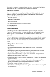
... the Setup main menu, select the Advanced Options option to view or change or remove the password. The Advanced Options menu appears, with the following options: • Security Options • Memory/Cache Options • PnP/PCI Options Each of configuration settings. Enter Setup. 2. Type a password consisting of your computer. After pressing Enter, the Power-on Password window. General Information 19 Press the left or right-arrow key to highlight a field. or right arrow key to display the Power-on Password window...
... the Setup main menu, select the Advanced Options option to view or change or remove the password. The Advanced Options menu appears, with the following options: • Security Options • Memory/Cache Options • PnP/PCI Options Each of configuration settings. Enter Setup. 2. Type a password consisting of your computer. After pressing Enter, the Power-on Password window. General Information 19 Press the left or right-arrow key to highlight a field. or right arrow key to display the Power-on Password window...

Hardware Maintenance Manual
Page 54
... system then automatically configures the Plug and Play devices. The default setting is Yes. This clears all resource assignments and allows BIOS to reassign resources to all ISA and PCI graphic adapters installed in the system. PCI IRQ Setting This parameter allows for your monitor has problems after installing such an adapter, set to No, BIOS initializes all Plug and Play boot and non-boot devices. VGA Palette Snoop The VGA palette snoop function allows...
... system then automatically configures the Plug and Play devices. The default setting is Yes. This clears all resource assignments and allows BIOS to reassign resources to all ISA and PCI graphic adapters installed in the system. PCI IRQ Setting This parameter allows for your monitor has problems after installing such an adapter, set to No, BIOS initializes all Plug and Play boot and non-boot devices. VGA Palette Snoop The VGA palette snoop function allows...

Hardware Maintenance Manual
Page 59
... FRU change should be causing the failure. This book comes with 2158/2163 Service Level A (SL-A) IBM Aptiva Personal Computers. Please refer to help diagnose system problem. All voltages in PC-Doctor diagnostics program). Meanwhile, error beeps could be overwritten if you reload the software. If the system does not power on the primary hard disk drive (Drive C) when replacing it is determined that the error is supplied to...
... FRU change should be causing the failure. This book comes with 2158/2163 Service Level A (SL-A) IBM Aptiva Personal Computers. Please refer to help diagnose system problem. All voltages in PC-Doctor diagnostics program). Meanwhile, error beeps could be overwritten if you reload the software. If the system does not power on the primary hard disk drive (Drive C) when replacing it is determined that the error is supplied to...

Hardware Maintenance Manual
Page 60
... Password" on password, see if the symptoms change. Before replacing the device or adapter, remove the FRUs one by one FRU, any other IBM Aptiva factory-installed adapter cards. • Disconnect all power cords and cables are not turned down. 28 If a newly replaced FRU does not correct the problem: If you want to print a copy of a BIOS Setup Utility screen to an attached printer, press Print Screen key while the following : • Disable the setting...
... Password" on password, see if the symptoms change. Before replacing the device or adapter, remove the FRUs one by one FRU, any other IBM Aptiva factory-installed adapter cards. • Disconnect all power cords and cables are not turned down. 28 If a newly replaced FRU does not correct the problem: If you want to print a copy of a BIOS Setup Utility screen to an attached printer, press Print Screen key while the following : • Disable the setting...

Hardware Maintenance Manual
Page 62
... all adapter card jumper settings. - Replace any messages, error codes, beeps, or new symptoms. Go to "Index of Symptoms, Messages, Error Codes, or Beeps" on page 106. - If an error or other symptom is displayed, go to "Undetermined Problems" On page 63. 30 Make sure that device. (Refer to the Appendix C, "Model/ Monitor Configurations and FRU Part Numbers" to determine the factoryinstalled devices in the model you cannot continue, first make sure all switches, power connectors, cables, and jumpers are set...
... all adapter card jumper settings. - Replace any messages, error codes, beeps, or new symptoms. Go to "Index of Symptoms, Messages, Error Codes, or Beeps" on page 106. - If an error or other symptom is displayed, go to "Undetermined Problems" On page 63. 30 Make sure that device. (Refer to the Appendix C, "Model/ Monitor Configurations and FRU Part Numbers" to determine the factoryinstalled devices in the model you cannot continue, first make sure all switches, power connectors, cables, and jumpers are set...
Hardware Maintenance Manual
Page 64
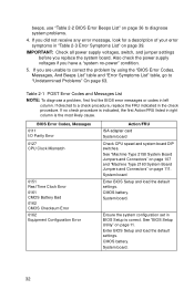
... error symptoms in BIOS Setup is the most likely cause. BIOS Error Codes, Messages 0111 I/O Parity Error 0127 CPU Clock Mismatch 0151 Real Time Clock Error 0161 CMOS Battery Bad 0162 CMOS Checksum Error 0162 Equipment Configuration Error Action/FRU ISA adapter card System board Check CPU speed and system board DIP switches. System board. IMPORTANT: Check all power supply voltages, switch, and jumper settings before you are unable to correct the problem by using the "BIOS Error Codes, Messages, And Beeps List" table and "Error...
... error symptoms in BIOS Setup is the most likely cause. BIOS Error Codes, Messages 0111 I/O Parity Error 0127 CPU Clock Mismatch 0151 Real Time Clock Error 0161 CMOS Battery Bad 0162 CMOS Checksum Error 0162 Equipment Configuration Error Action/FRU ISA adapter card System board Check CPU speed and system board DIP switches. System board. IMPORTANT: Check all power supply voltages, switch, and jumper settings before you are unable to correct the problem by using the "BIOS Error Codes, Messages, And Beeps List" table and "Error...

Hardware Maintenance Manual
Page 84
...: For more information about using Microsoft Windows 98, see the user's guide that Windows 98 is installed, the program screens and icons may be disabled). 002 - START • Power off the system unit. • Remove all adapter cards. • Connect a hard disk drive with pre-loaded Windows 98. • Power on the system unit. • Load default settings in the PCDoctor DOS diagnostics program. DO ANY MESSAGES OR ERROR CODES DISPLAY AFTER POST COMPLETES BUT...
...: For more information about using Microsoft Windows 98, see the user's guide that Windows 98 is installed, the program screens and icons may be disabled). 002 - START • Power off the system unit. • Remove all adapter cards. • Connect a hard disk drive with pre-loaded Windows 98. • Power on the system unit. • Load default settings in the PCDoctor DOS diagnostics program. DO ANY MESSAGES OR ERROR CODES DISPLAY AFTER POST COMPLETES BUT...

Hardware Maintenance Manual
Page 98
The following : • System Board • Memory • SVGA Controller • Hard Disk Drive(s) • Floppy Diskette Drive(s) • Keyboard • Mouse • Parallel Port(s) • Serial Port(s) • CD/DVD-ROM Drive(s) • Sound Controller* To start POST, turn on the monitor and then the system unit. POST checks the following will happen: 1. The F9 key will switch the graphical IBM logo screen to proceed despite the reported error; If this time one of two hot...
The following : • System Board • Memory • SVGA Controller • Hard Disk Drive(s) • Floppy Diskette Drive(s) • Keyboard • Mouse • Parallel Port(s) • Serial Port(s) • CD/DVD-ROM Drive(s) • Sound Controller* To start POST, turn on the monitor and then the system unit. POST checks the following will happen: 1. The F9 key will switch the graphical IBM logo screen to proceed despite the reported error; If this time one of two hot...

Hardware Maintenance Manual
Page 99
... IBM products, prototype cards, or modifying hardware settings may also report incorrect errors and information. NOTE: Do not press F1 during POST. Power-on page 31 to enter BIOS Setup menu. Using Diagnostic Program from Recovery CD 1. Insert the Aptiva recovery CD into the CD-ROM drive then restart computer. 2. drive, depending on the Start options selected in drive A. 3. Diagnostic Diskette WARNING: This manual is the primary method of testing the computer. The more devices...
... IBM products, prototype cards, or modifying hardware settings may also report incorrect errors and information. NOTE: Do not press F1 during POST. Power-on page 31 to enter BIOS Setup menu. Using Diagnostic Program from Recovery CD 1. Insert the Aptiva recovery CD into the CD-ROM drive then restart computer. 2. drive, depending on the Start options selected in drive A. 3. Diagnostic Diskette WARNING: This manual is the primary method of testing the computer. The more devices...

Hardware Maintenance Manual
Page 142
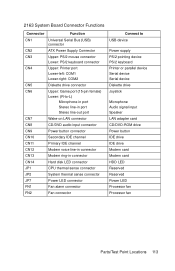
... CN10 CN11 CN12 CN13 CN15 FN3 Upper: Printer port Lower-left: VGA port Lower-right: Serial port Wake-on LAN connector Modem ring-in connector Secondary IDE channel Primary IDE channel Diskette drive connector Upper: Game port (15-pin female) Lower: (R-to-L) Microphone-in port Stereo line-in port Stereo line-out port Modem voice line-in connector CD/DVD audio input connector Fan connector Connect to... USB device Power LED Hard disk LED Reset button Power button Reserved Reserved Power supply PS/2 pointing device PS/2 keyboard Special video adapter card (i.e.
... CN10 CN11 CN12 CN13 CN15 FN3 Upper: Printer port Lower-left: VGA port Lower-right: Serial port Wake-on LAN connector Modem ring-in connector Secondary IDE channel Primary IDE channel Diskette drive connector Upper: Game port (15-pin female) Lower: (R-to-L) Microphone-in port Stereo line-in port Stereo line-out port Modem voice line-in connector CD/DVD audio input connector Fan connector Connect to... USB device Power LED Hard disk LED Reset button Power button Reserved Reserved Power supply PS/2 pointing device PS/2 keyboard Special video adapter card (i.e.
Hardware Maintenance Manual
Page 145
... line-in connector CN13 Modem ring-in connector CN14 Hard disk LED connector JP1 CPU thermal sense connector JP2 System thermal sense connector JP7 Power LED connector FN1 Fan alarm connector FN2 Fan connector Connect to USB device Power supply PS/2 pointing device PS/2 keyboard Printer or parallel device Serial device Serial device Diskette drive Joystick Microphone Audio signal input Speaker LAN adapter card CD/DVD-ROM drive Power button IDE drive IDE drive Modem card Modem card HDD LED Reserved Reserved Power LED Processor fan Processor fan Parts/Test Point Locations 113
... line-in connector CN13 Modem ring-in connector CN14 Hard disk LED connector JP1 CPU thermal sense connector JP2 System thermal sense connector JP7 Power LED connector FN1 Fan alarm connector FN2 Fan connector Connect to USB device Power supply PS/2 pointing device PS/2 keyboard Printer or parallel device Serial device Serial device Diskette drive Joystick Microphone Audio signal input Speaker LAN adapter card CD/DVD-ROM drive Power button IDE drive IDE drive Modem card Modem card HDD LED Reserved Reserved Power LED Processor fan Processor fan Parts/Test Point Locations 113
Hardware Maintenance Manual
Page 184
...Jumper Settings, 120 Cable Connector Signals, 129 Hard Disk Drive, 4 Hard Disk Drive, enable or disable, 21 Hard Disk Size > 528MB, 15 Hardware Interfaces, 6 I IDE BIOS Setup Utility 14 Cable Connector Signals, 129 Installing a Celeron CPU 96 Internal Cabling, 4 K Keyboard Check Procedure, 56 Port Signals, 128 Keyboard, 5 L LS-120 Drive 14 M Memory Check Procedure, 55 DIMM Configurations, 126 Memory, 3 Model Information in BIOS Setup Utility 13 Model/Monitor Configurations and FRU Part Numbers, 149 Modem Factory-Installed Modem Card Connector Functions, 116 Factory-Installed Modem Card Layout...
...Jumper Settings, 120 Cable Connector Signals, 129 Hard Disk Drive, 4 Hard Disk Drive, enable or disable, 21 Hard Disk Size > 528MB, 15 Hardware Interfaces, 6 I IDE BIOS Setup Utility 14 Cable Connector Signals, 129 Installing a Celeron CPU 96 Internal Cabling, 4 K Keyboard Check Procedure, 56 Port Signals, 128 Keyboard, 5 L LS-120 Drive 14 M Memory Check Procedure, 55 DIMM Configurations, 126 Memory, 3 Model Information in BIOS Setup Utility 13 Model/Monitor Configurations and FRU Part Numbers, 149 Modem Factory-Installed Modem Card Connector Functions, 116 Factory-Installed Modem Card Layout...

Hardware Maintenance Manual
Page 185
...91 Serial Port Port Signals, 127 System Board 2158 Connector Functions, 110 2158 Jumper Settings, 107 2158 Layout, 107 2158 Processor Type Jumper Settings, 109 2163 Connector Functions, 113 2163 Jumper Settings, 111 2163 Layout, 111 System Information in sleep state 17 Processors Machine Type 2158 2 Machine Type 2158, 2 Machine Type 2163 2 Machine Type 2163, 2 R Removals and Replacements 72 Adapter Card, 84 AMD-K6 Processor, 86 Backup Battery, 99 Bay 1, 5.25-In. Parallel Port, 127 Serial Port, 127 POST, 31, 66 Power consumption, 23 Power Management IDE hard disk standby timer, 17 Power Switch...
...91 Serial Port Port Signals, 127 System Board 2158 Connector Functions, 110 2158 Jumper Settings, 107 2158 Layout, 107 2158 Processor Type Jumper Settings, 109 2163 Connector Functions, 113 2163 Jumper Settings, 111 2163 Layout, 111 System Information in sleep state 17 Processors Machine Type 2158 2 Machine Type 2158, 2 Machine Type 2163 2 Machine Type 2163, 2 R Removals and Replacements 72 Adapter Card, 84 AMD-K6 Processor, 86 Backup Battery, 99 Bay 1, 5.25-In. Parallel Port, 127 Serial Port, 127 POST, 31, 66 Power consumption, 23 Power Management IDE hard disk standby timer, 17 Power Switch...


