
Owner's Manual
Page 1
Zone Thermostat Heating/Cooling Thermostat and Subbase or Wallplate Model T8090T OWNER'S MANUAL 69-0432-1
Zone Thermostat Heating/Cooling Thermostat and Subbase or Wallplate Model T8090T OWNER'S MANUAL 69-0432-1
Owner's Manual
Page 2
... of comfort plus energy savings when programmed according to the instructions in the trash at 1-800-468-1502. 2 69-0432-1 Your new thermostat will automatically control the temperature in your home to provide a high level of its useful life. Do not place control in this control ...is replacing a control that contains mercury in a sealed tube, do not place your new Honeywell Trol-A-Temp Zone® Thermostat. Welcome to the world of an old control containing mercury in a sealed tube. Contact your local waste management authority for instructions...
... of comfort plus energy savings when programmed according to the instructions in the trash at 1-800-468-1502. 2 69-0432-1 Your new thermostat will automatically control the temperature in your home to provide a high level of its useful life. Do not place control in this control ...is replacing a control that contains mercury in a sealed tube, do not place your new Honeywell Trol-A-Temp Zone® Thermostat. Welcome to the world of an old control containing mercury in a sealed tube. Contact your local waste management authority for instructions...
Owner's Manual
Page 3
Table of Contents PAGE Features of Your Thermostat ...4 Setting the Temperature ...7 Inserting Clock Batteries ...8 Setting the Clock ...9 Programming ...11 Troubleshooting ...15 Servicing the Thermostat ...21 Heat Anticipator Setting ...21 Thermometer Adjustment ...22 3 69-0432-1
Table of Contents PAGE Features of Your Thermostat ...4 Setting the Temperature ...7 Inserting Clock Batteries ...8 Setting the Clock ...9 Programming ...11 Troubleshooting ...15 Servicing the Thermostat ...21 Heat Anticipator Setting ...21 Thermometer Adjustment ...22 3 69-0432-1
Owner's Manual
Page 4
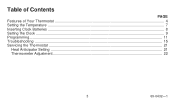
Features of day as set clock for 24-hour dial. 7 PROGRAM INDEX WHEEL. Arrow head indicates time for energy savings and normal temperature periods. 2 THERMOSTAT COVER. 3 THERMOMETER. Left (blue mark) controls the low temperature; ture. 4 69-0432-1 Turn minute hand clock- Lift it up to set by program pins. 8 TEMPERATURE .... 5 CLOCK HANDS. right (red mark) controls the high tempera- Provides accurate room temperature reading. 4 CLOCK. Controls high and low temperature at specific time of Your Thermostat 1 2 M8693 3 1 FLIP-UP COVER.
Features of day as set clock for 24-hour dial. 7 PROGRAM INDEX WHEEL. Arrow head indicates time for energy savings and normal temperature periods. 2 THERMOSTAT COVER. 3 THERMOMETER. Left (blue mark) controls the low temperature; ture. 4 69-0432-1 Turn minute hand clock- Lift it up to set by program pins. 8 TEMPERATURE .... 5 CLOCK HANDS. right (red mark) controls the high tempera- Provides accurate room temperature reading. 4 CLOCK. Controls high and low temperature at specific time of Your Thermostat 1 2 M8693 3 1 FLIP-UP COVER.
Owner's Manual
Page 8
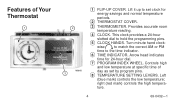
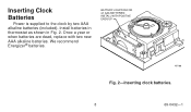
INSTALL WITH POSITIVE ENDS UP M7188 Fig. 2-Inserting clock batteries. 8 69-0432-1 BATTERY LOCATION FOR (2) AAA BATTERIES; We recommend Energizer® batteries. Once a year or when batteries are dead, replace with two new AAA alkaline batteries. Inserting Clock Batteries Power is supplied to the clock by two AAA alkaline batteries (included). Install batteries in thermostat as shown in Fig. 2.
INSTALL WITH POSITIVE ENDS UP M7188 Fig. 2-Inserting clock batteries. 8 69-0432-1 BATTERY LOCATION FOR (2) AAA BATTERIES; We recommend Energizer® batteries. Once a year or when batteries are dead, replace with two new AAA alkaline batteries. Inserting Clock Batteries Power is supplied to the clock by two AAA alkaline batteries (included). Install batteries in thermostat as shown in Fig. 2.
Owner's Manual
Page 9
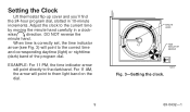
Setting the Clock Lift thermostat flip-up cover and you'll find the 24-hour program dial, slotted in a clock- wise direction. MINUTE HAND TIME INDICATOR ARROW M8561 Fig. 3-Setting ...
Setting the Clock Lift thermostat flip-up cover and you'll find the 24-hour program dial, slotted in a clock- wise direction. MINUTE HAND TIME INDICATOR ARROW M8561 Fig. 3-Setting ...
Owner's Manual
Page 11
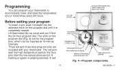
FLIP-UP COVER 24-HOUR PROGRAM DIAL (GRAY AREA FOR NIGHT SETTINGS Before setting your thermostat. A heating program is completely seated. ■ Lift thermostat flip-up cover and you'll find the 24-hour program dial. A red PROGRAM PINS THERMOSTAT COVER PROGRAM PIN SLOT PROGRAM INDEX WHEEL MANUAL PROGRAM ADVANCE BUTTON PROGRAM PIN STORAGE... You can be inserted at 10-minute intervals. ■ Three red and three blue program pins are for the program pins, which can program your thermostat to automatically lower and raise the temperature one or more times every 24 hours.
FLIP-UP COVER 24-HOUR PROGRAM DIAL (GRAY AREA FOR NIGHT SETTINGS Before setting your thermostat. A heating program is completely seated. ■ Lift thermostat flip-up cover and you'll find the 24-hour program dial. A red PROGRAM PINS THERMOSTAT COVER PROGRAM PIN SLOT PROGRAM INDEX WHEEL MANUAL PROGRAM ADVANCE BUTTON PROGRAM PIN STORAGE... You can be inserted at 10-minute intervals. ■ Three red and three blue program pins are for the program pins, which can program your thermostat to automatically lower and raise the temperature one or more times every 24 hours.
Owner's Manual
Page 15
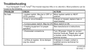
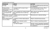
...power. Most problems can be in OFF or Move system switch to ON. -heating equipment for correct terminal hookups. Check for proper operation. -thermostat connections. If blown or tripped, replace fuse or reset breaker. -furnace power switch. See manufacturer's instructions. Firmly tighten all terminal screws. -... closed, contact a qualified service technician for assistance. (continued) 69-0432-1 PROBLEM CHECK ACTION No heat. -system switch. Troubleshooting Your Honeywell Trol-A-Temp® Thermostat requires little or no attention. Repair any frayed or broken wires.
...power. Most problems can be in OFF or Move system switch to ON. -heating equipment for correct terminal hookups. Check for proper operation. -thermostat connections. If blown or tripped, replace fuse or reset breaker. -furnace power switch. See manufacturer's instructions. Firmly tighten all terminal screws. -... closed, contact a qualified service technician for assistance. (continued) 69-0432-1 PROBLEM CHECK ACTION No heat. -system switch. Troubleshooting Your Honeywell Trol-A-Temp® Thermostat requires little or no attention. Repair any frayed or broken wires.
Owner's Manual
Page 16
... subbase system switch. 1 Move to desired operating position. -air flow at programmed May need more time to warm up the program dial. levers. -position of thermostat setpoint Reset to desired settings. Energy saving -program dial for assistance. (continued) 16 69-0432-1 Move red pin one-half hour earlier on up at...
... subbase system switch. 1 Move to desired operating position. -air flow at programmed May need more time to warm up the program dial. levers. -position of thermostat setpoint Reset to desired settings. Energy saving -program dial for assistance. (continued) 16 69-0432-1 Move red pin one-half hour earlier on up at...
Owner's Manual
Page 17
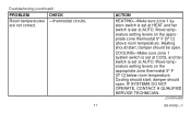
... set at COOL and fan switch is set at AUTO. Cooling should be open . Move temperature setting levers on the appropriate zone thermostat 5° F [3° C] above room temperature. are not correct. 17 ACTION HEATING-Make sure zone 1 system switch is set... at HEAT and fan switch is set at AUTO. Troubleshooting (continued) PROBLEM CHECK Room temperatures -thermostat circuits. damper should start ; Move temperature setting levers on the appropriate zone thermostat 5° F [3° C] below room temperature. Heating should open . IF SYSTEMS DO NOT OPERATE, ...
... set at COOL and fan switch is set at AUTO. Cooling should be open . Move temperature setting levers on the appropriate zone thermostat 5° F [3° C] above room temperature. are not correct. 17 ACTION HEATING-Make sure zone 1 system switch is set... at HEAT and fan switch is set at AUTO. Troubleshooting (continued) PROBLEM CHECK Room temperatures -thermostat circuits. damper should start ; Move temperature setting levers on the appropriate zone thermostat 5° F [3° C] below room temperature. Heating should open . IF SYSTEMS DO NOT OPERATE, ...
Owner's Manual
Page 18
See manufacturer instructions. If fuse is closed . -other. 18 ACTION Move switch to ON position. Check for proper operation. -thermostat connections. -airflow at register. Firmly tighten all terminal screws. Turn Off power. May be closed , contact a qualified service technician for assistance. (continued) 69-0432-1 Located ...
See manufacturer instructions. If fuse is closed . -other. 18 ACTION Move switch to ON position. Check for proper operation. -thermostat connections. -airflow at register. Firmly tighten all terminal screws. Turn Off power. May be closed , contact a qualified service technician for assistance. (continued) 69-0432-1 Located ...
Owner's Manual
Page 19
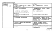
..., 1-800-828-8367 for drafts or radiant heat. -calibration of thermometer. Use a spirit level. -area around thermostat for additional assistance. 19 69-0432-1 Troubleshooting (continued) PROBLEM Clock does not run. Contact qualified service technician for cause and action.... Thermostat setting and thermometer reading disagree. Thermostat should be about 5 ft [1.5m] above floor on heating-only system. ACTION Remove thermostat from the wallplate or subbase, and measure the voltage. Refer to page ...
..., 1-800-828-8367 for drafts or radiant heat. -calibration of thermometer. Use a spirit level. -area around thermostat for additional assistance. 19 69-0432-1 Troubleshooting (continued) PROBLEM Clock does not run. Contact qualified service technician for cause and action.... Thermostat setting and thermometer reading disagree. Thermostat should be about 5 ft [1.5m] above floor on heating-only system. ACTION Remove thermostat from the wallplate or subbase, and measure the voltage. Refer to page ...
Owner's Manual
Page 20
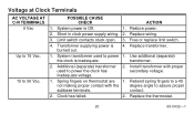
...Terminals AC VOLTAGE AT C-R TERMINALS 0 Vac Up to 15 Vac. 15 to power the clock has inadequate voltage. 2. Replace the thermostat. 20 69-0432-1 Additional (separate) transformer used to a 45 not making proper contact with proper secondary voltage. 1. Rebend spring ...fingers to power 1. Transformer supplying power is Off. 1. Use additional (separate) the clock is inadequate. Spring fingers on thermostat are 1. POSSIBLE CAUSE CHECK ACTION 1. Replace wiring. 3. Limit switch contacts stuck open. 3. System transformer used to 30 Vac. Short ...
...Terminals AC VOLTAGE AT C-R TERMINALS 0 Vac Up to 15 Vac. 15 to power the clock has inadequate voltage. 2. Replace the thermostat. 20 69-0432-1 Additional (separate) transformer used to a 45 not making proper contact with proper secondary voltage. 1. Rebend spring ...fingers to power 1. Transformer supplying power is Off. 1. Use additional (separate) the clock is inadequate. Spring fingers on thermostat are 1. POSSIBLE CAUSE CHECK ACTION 1. Replace wiring. 3. Limit switch contacts stuck open. 3. System transformer used to 30 Vac. Short ...
Owner's Manual
Page 21
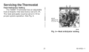
Servicing the Thermostat Heat Anticipator Setting The T8090T Thermostat has an adjustable heat anticipator that was factory-set at 0.1A. The heat anticipator must be set at 0.1A for proper system operation. MOVE INDICATOR TO 0.1A M8596 Fig. 6-Heat anticipator setting. 21 69-0432-1 See Fig. 6.
Servicing the Thermostat Heat Anticipator Setting The T8090T Thermostat has an adjustable heat anticipator that was factory-set at 0.1A. The heat anticipator must be set at 0.1A for proper system operation. MOVE INDICATOR TO 0.1A M8596 Fig. 6-Heat anticipator setting. 21 69-0432-1 See Fig. 6.
Owner's Manual
Page 22
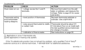
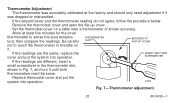
... are the same, replace the cover and put the system into operation. M1810 Fig. 7-Thermometer adjustment. 22 69-0432-1 Remove the thermostat cover and open the flip-up cover. Thermometer Adjustment The thermometer was dropped or mishandled. Allow at the factory and should only need ...the cover thermometer to touch the thermometer or breathe on a table near a thermometer of known accuracy. then compare the readings. Replace thermostat cover and put the system into operation. If the setpoint lever and the thermometer reading do not agree, follow the procedure below. Set...
... are the same, replace the cover and put the system into operation. M1810 Fig. 7-Thermometer adjustment. 22 69-0432-1 Remove the thermostat cover and open the flip-up cover. Thermometer Adjustment The thermometer was dropped or mishandled. Allow at the factory and should only need ...the cover thermometer to touch the thermometer or breathe on a table near a thermometer of known accuracy. then compare the readings. Replace thermostat cover and put the system into operation. If the setpoint lever and the thermometer reading do not agree, follow the procedure below. Set...
Owner's Manual
Page 23
Before you have the following information available: Make and model of your furnace, old thermostat and air conditioner. 23 69-0432-1 If you call, please have questions regarding the installation and programming of your Honeywell Trol-ATemp® Thermostat, please contact a Trol-A-Temp® customer servoce re[resentative at 1-800- 828-8367.
Before you have the following information available: Make and model of your furnace, old thermostat and air conditioner. 23 69-0432-1 If you call, please have questions regarding the installation and programming of your Honeywell Trol-ATemp® Thermostat, please contact a Trol-A-Temp® customer servoce re[resentative at 1-800- 828-8367.


