
Owner's Manual
Page 1
Zone Thermostat Heating/Cooling Thermostat and Subbase or Wallplate Model T8090T OWNER'S MANUAL 69-0432-1
Zone Thermostat Heating/Cooling Thermostat and Subbase or Wallplate Model T8090T OWNER'S MANUAL 69-0432-1
Owner's Manual
Page 2
.... at the end of its useful life. If you heat or cool each zone provides additional energy savings. Your new thermostat will automatically control the temperature in your new Honeywell Trol-A-Temp Zone® Thermostat. Welcome to the world of energy savings with your home to provide a high level of comfort plus energy savings when programmed according to the instructions in this control is replacing a control that contains mercury in...
.... at the end of its useful life. If you heat or cool each zone provides additional energy savings. Your new thermostat will automatically control the temperature in your new Honeywell Trol-A-Temp Zone® Thermostat. Welcome to the world of energy savings with your home to provide a high level of comfort plus energy savings when programmed according to the instructions in this control is replacing a control that contains mercury in...
Owner's Manual
Page 3
Table of Contents PAGE Features of Your Thermostat ...4 Setting the Temperature ...7 Inserting Clock Batteries ...8 Setting the Clock ...9 Programming ...11 Troubleshooting ...15 Servicing the Thermostat ...21 Heat Anticipator Setting ...21 Thermometer Adjustment ...22 3 69-0432-1
Table of Contents PAGE Features of Your Thermostat ...4 Setting the Temperature ...7 Inserting Clock Batteries ...8 Setting the Clock ...9 Programming ...11 Troubleshooting ...15 Servicing the Thermostat ...21 Heat Anticipator Setting ...21 Thermometer Adjustment ...22 3 69-0432-1
Owner's Manual
Page 4
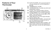
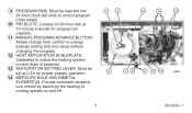
... PM time to hold the programming pins. 5 CLOCK HANDS. Left (blue mark) controls the low temperature; Features of day as set clock for 24-hour dial. 7 PROGRAM INDEX WHEEL. This clock provides a 24-hour slotted dial to the time indicator. 6 TIME INDICATOR. Turn minute hand clock- right (red mark) controls the high tempera- ture. 4 69-0432-1 Arrow head indicates time for energy savings and normal temperature periods. 2 THERMOSTAT COVER. 3 THERMOMETER. Controls high and low temperature at specific time of Your Thermostat 1 2 M8693...
... PM time to hold the programming pins. 5 CLOCK HANDS. Left (blue mark) controls the low temperature; Features of day as set clock for 24-hour dial. 7 PROGRAM INDEX WHEEL. This clock provides a 24-hour slotted dial to the time indicator. 6 TIME INDICATOR. Turn minute hand clock- right (red mark) controls the high tempera- ture. 4 69-0432-1 Arrow head indicates time for energy savings and normal temperature periods. 2 THERMOSTAT COVER. 3 THERMOMETER. Controls high and low temperature at specific time of Your Thermostat 1 2 M8693...
Owner's Manual
Page 5
... M8691 5 69-0432-1 9 PROGRAM PINS. Provide automatic temperature control by switching the heating or cooling system on 24-hour dial at 0.1A for program pin insertion. 11 MANUAL PROGRAM ADVANCE BUTTON. Must be inserted into 24-hour clock dial slots to match the heating system current draw in amperes. 13 ANTICIPATOR SETTING LEVER. Must be set at 10-minute intervals for proper system operation. 14 MERCURY BULB...
... M8691 5 69-0432-1 9 PROGRAM PINS. Provide automatic temperature control by switching the heating or cooling system on 24-hour dial at 0.1A for program pin insertion. 11 MANUAL PROGRAM ADVANCE BUTTON. Must be inserted into 24-hour clock dial slots to match the heating system current draw in amperes. 13 ANTICIPATOR SETTING LEVER. Must be set at 10-minute intervals for proper system operation. 14 MERCURY BULB...
Owner's Manual
Page 6
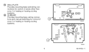
tions and manual switching for control of 15 zone 1 in heating or heating-cooling systems. 16 SUBBASE Provides mounting base, wiring connec- nections for control of zones other than zone 1 in heating or heating-cooling systems. 16 6 M2421 W G Y R M8690 69-0432-1 15 WALLPLATE Provides mounting base and wiring con-
tions and manual switching for control of 15 zone 1 in heating or heating-cooling systems. 16 SUBBASE Provides mounting base, wiring connec- nections for control of zones other than zone 1 in heating or heating-cooling systems. 16 6 M2421 W G Y R M8690 69-0432-1 15 WALLPLATE Provides mounting base and wiring con-
Owner's Manual
Page 7
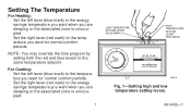
... override the time program by Honeywell M641A Fig. 1-Setting high and low temperature setting levers. 69-0432-1 ture you are sleeping or the associated zone is unoccupied. 7 LOW TEMPERATURE SETTING LEVER (BLUE MARK) 4 3 2 1 12 11 12 9 10 8 7 6 5 3 4 9 2 3 1 12 11 10 9 8 7 6 5 6 50 60 70 80 HIGH TEMPERATURE SETTING LEVER (RED MARK) 50 60 70 80 by setting both the red and blue levers to the same temperature setpoint. Setting The Temperature...
... override the time program by Honeywell M641A Fig. 1-Setting high and low temperature setting levers. 69-0432-1 ture you are sleeping or the associated zone is unoccupied. 7 LOW TEMPERATURE SETTING LEVER (BLUE MARK) 4 3 2 1 12 11 12 9 10 8 7 6 5 3 4 9 2 3 1 12 11 10 9 8 7 6 5 6 50 60 70 80 HIGH TEMPERATURE SETTING LEVER (RED MARK) 50 60 70 80 by setting both the red and blue levers to the same temperature setpoint. Setting The Temperature...
Owner's Manual
Page 11
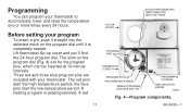
... intervals. ■ Three red and three blue program pins are for the program pins, which can program your thermostat. FLIP-UP COVER 24-HOUR PROGRAM DIAL (GRAY AREA FOR NIGHT SETTINGS Before setting your program ■ To insert a pin, push it is preprogrammed. the blue pins start the high-temperature period; A red PROGRAM PINS THERMOSTAT COVER PROGRAM PIN SLOT PROGRAM INDEX WHEEL MANUAL PROGRAM ADVANCE BUTTON PROGRAM PIN STORAGE TIME INDICATOR ARROW M8692 Fig...
... intervals. ■ Three red and three blue program pins are for the program pins, which can program your thermostat. FLIP-UP COVER 24-HOUR PROGRAM DIAL (GRAY AREA FOR NIGHT SETTINGS Before setting your program ■ To insert a pin, push it is preprogrammed. the blue pins start the high-temperature period; A red PROGRAM PINS THERMOSTAT COVER PROGRAM PIN SLOT PROGRAM INDEX WHEEL MANUAL PROGRAM ADVANCE BUTTON PROGRAM PIN STORAGE TIME INDICATOR ARROW M8692 Fig...
Owner's Manual
Page 12
You can set up to six temperature changes with the program index wheel. ■ On heating/cooling systems, be sure to reset the pins when the seasons change a pin if it is engaged with the pins supplied. DO NOT attempt to change the pins add a new energy saving period. ■ To remove a pin, press against the program dial and pull the pin straight out...
You can set up to six temperature changes with the program index wheel. ■ On heating/cooling systems, be sure to reset the pins when the seasons change a pin if it is engaged with the pins supplied. DO NOT attempt to change the pins add a new energy saving period. ■ To remove a pin, press against the program dial and pull the pin straight out...
Owner's Manual
Page 13
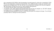
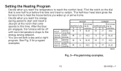
... that corresponds to this time and insert a red pin. The half-hour head start and insert a blue pin at the notch that is one-half hour before you wake up or arrive home. ■ Decide when you want the energy saving period to start gives the furnace time to heat the house before this time. Setting the Heating Program ■ Decide when...
... that corresponds to this time and insert a red pin. The half-hour head start and insert a blue pin at the notch that is one-half hour before you wake up or arrive home. ■ Decide when you want the energy saving period to start gives the furnace time to heat the house before this time. Setting the Heating Program ■ Decide when...
Owner's Manual
Page 14
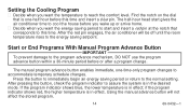
... Cooling Program ■ Decide when you want the temperature to reach the comfort level. Press the button to immediately begin an energy saving period or return to the program advance mechanism, DO NOT use the program advance button within a 30-minute period before this time. if the program indicator shows red, the higher temperature is in the desired mode. The half-hour head start gives the air conditioner time to cool the house...
... Cooling Program ■ Decide when you want the temperature to reach the comfort level. Press the button to immediately begin an energy saving period or return to the program advance mechanism, DO NOT use the program advance button within a 30-minute period before this time. if the program indicator shows red, the higher temperature is in the desired mode. The half-hour head start gives the air conditioner time to cool the house...
Owner's Manual
Page 15
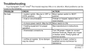
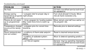
... switch to the following. Repair any frayed or broken wires. Zone damper may be traced to ON. -heating equipment for assistance. (continued) 69-0432-1 Firmly tighten all terminal screws. -airflow at register. Turn Off power. See manufacturer's instructions. Check for correct terminal hookups. Most problems can be closed. 15 If damper is closed, contact a qualified service technician for proper operation. -thermostat connections. Troubleshooting Your Honeywell Trol-A-Temp...
... switch to the following. Repair any frayed or broken wires. Zone damper may be traced to ON. -heating equipment for assistance. (continued) 69-0432-1 Firmly tighten all terminal screws. -airflow at register. Turn Off power. See manufacturer's instructions. Check for correct terminal hookups. Most problems can be closed. 15 If damper is closed, contact a qualified service technician for proper operation. -thermostat connections. Troubleshooting Your Honeywell Trol-A-Temp...
Owner's Manual
Page 16
... system switch. 1 Move to desired operating position. -air flow at programmed May need more time to warm up at register. Energy saving -program dial for heating system. Relocate pins to desired temperatures. levers. -position of thermostat setpoint Reset to desired settings. Move red pin one-half hour earlier on up the program dial. time. Rooms do not warm -timer program for proper day or temperature program night phase. 12 hours off. Turn clock...
... system switch. 1 Move to desired operating position. -air flow at programmed May need more time to warm up at register. Energy saving -program dial for heating system. Relocate pins to desired temperatures. levers. -position of thermostat setpoint Reset to desired settings. Move red pin one-half hour earlier on up the program dial. time. Rooms do not warm -timer program for proper day or temperature program night phase. 12 hours off. Turn clock...
Owner's Manual
Page 17
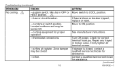
... 1 system switch is set at COOL and fan switch is set at AUTO. damper should be open . are not correct. 17 ACTION HEATING-Make sure zone 1 system switch is set at HEAT and fan switch is set at AUTO. Move temperature setting levers on the appropriate zone thermostat 5° F [3° C] above room temperature. Cooling should start ; Move temperature setting levers on the appropriate zone thermostat 5° F [3° C] below room temperature. Troubleshooting (continued) PROBLEM CHECK Room temperatures -thermostat circuits.
... 1 system switch is set at COOL and fan switch is set at AUTO. damper should be open . are not correct. 17 ACTION HEATING-Make sure zone 1 system switch is set at HEAT and fan switch is set at AUTO. Move temperature setting levers on the appropriate zone thermostat 5° F [3° C] above room temperature. Cooling should start ; Move temperature setting levers on the appropriate zone thermostat 5° F [3° C] below room temperature. Troubleshooting (continued) PROBLEM CHECK Room temperatures -thermostat circuits.
Owner's Manual
Page 18
... HEAT position. 1 -fuse or circuit breaker. -condenser switch position. If fuse is closed . -other. 18 ACTION Move switch to ON position. Turn Off power. See manufacturer instructions. Check for proper operation. -thermostat connections. -airflow at register. Contact a qualified service technician for assistance. Move to COOL position. If damper is blown or breaker tripped, replace or reset. Repair any frayed or broken wires. Firmly tighten all terminal...
... HEAT position. 1 -fuse or circuit breaker. -condenser switch position. If fuse is closed . -other. 18 ACTION Move switch to ON position. Turn Off power. See manufacturer instructions. Check for proper operation. -thermostat connections. -airflow at register. Contact a qualified service technician for assistance. Move to COOL position. If damper is blown or breaker tripped, replace or reset. Repair any frayed or broken wires. Firmly tighten all terminal...
Owner's Manual
Page 19
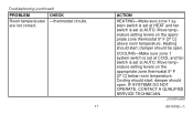
Thermostat setting and thermometer reading disagree. See instructions on page 22. 1 Applicable on zone 1 thermostat only. 2 Not applicable on an inside wall. Refer to page 20 for change of location. Use a spirit level. -area around thermostat for additional assistance. 19 69-0432-1 Reinstall thermostat wallplate or subbase. Troubleshooting (continued) PROBLEM Clock does not run. CHECK -voltage across the C and R terminals. -level position of thermometer. ACTION Remove thermostat from the...
Thermostat setting and thermometer reading disagree. See instructions on page 22. 1 Applicable on zone 1 thermostat only. 2 Not applicable on an inside wall. Refer to page 20 for change of location. Use a spirit level. -area around thermostat for additional assistance. 19 69-0432-1 Reinstall thermostat wallplate or subbase. Troubleshooting (continued) PROBLEM Clock does not run. CHECK -voltage across the C and R terminals. -level position of thermometer. ACTION Remove thermostat from the...
Owner's Manual
Page 20
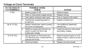
... power the clock has inadequate voltage. 2. Transformer supplying power is inadequate. Use additional (separate) the clock is burned out. 4. POSSIBLE CAUSE CHECK ACTION 1. Clock has failed. 2. contact. 2. System power is Off. 1. Restore power. 2. Free or replace limit switch. 4. Replace wiring. 3. Limit switch contacts stuck open. 3. System transformer used to power 1. Spring fingers on thermostat are 1. Voltage at Clock Terminals AC VOLTAGE AT C-R TERMINALS 0 Vac Up to 15 Vac. 15 to assure proper subbase terminals. Install...
... power the clock has inadequate voltage. 2. Transformer supplying power is inadequate. Use additional (separate) the clock is burned out. 4. POSSIBLE CAUSE CHECK ACTION 1. Clock has failed. 2. contact. 2. System power is Off. 1. Restore power. 2. Free or replace limit switch. 4. Replace wiring. 3. Limit switch contacts stuck open. 3. System transformer used to power 1. Spring fingers on thermostat are 1. Voltage at Clock Terminals AC VOLTAGE AT C-R TERMINALS 0 Vac Up to 15 Vac. 15 to assure proper subbase terminals. Install...
Owner's Manual
Page 21
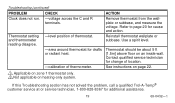
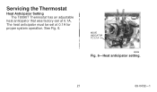
MOVE INDICATOR TO 0.1A M8596 Fig. 6-Heat anticipator setting. 21 69-0432-1 See Fig. 6. The heat anticipator must be set at 0.1A for proper system operation. Servicing the Thermostat Heat Anticipator Setting The T8090T Thermostat has an adjustable heat anticipator that was factory-set at 0.1A.
MOVE INDICATOR TO 0.1A M8596 Fig. 6-Heat anticipator setting. 21 69-0432-1 See Fig. 6. The heat anticipator must be set at 0.1A for proper system operation. Servicing the Thermostat Heat Anticipator Setting The T8090T Thermostat has an adjustable heat anticipator that was factory-set at 0.1A.
Owner's Manual
Page 22
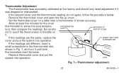
.... Be careful SLOT BACKSIDE OF FLIP-UP COVER not to sense the area tempera- Replace thermostat cover and put the system into operation. M1810 Fig. 7-Thermometer adjustment. 22 69-0432-1 If the readings are different, insert a small screwdriver in the thermometer slot, shown in Fig. 7, and turn it . Set the thermostat cover on it until both thermometers read the same...
.... Be careful SLOT BACKSIDE OF FLIP-UP COVER not to sense the area tempera- Replace thermostat cover and put the system into operation. M1810 Fig. 7-Thermometer adjustment. 22 69-0432-1 If the readings are different, insert a small screwdriver in the thermometer slot, shown in Fig. 7, and turn it . Set the thermostat cover on it until both thermometers read the same...
Owner's Manual
Page 23
If you call, please have questions regarding the installation and programming of your Honeywell Trol-ATemp® Thermostat, please contact a Trol-A-Temp® customer servoce re[resentative at 1-800- 828-8367. Before you have the following information available: Make and model of your furnace, old thermostat and air conditioner. 23 69-0432-1
If you call, please have questions regarding the installation and programming of your Honeywell Trol-ATemp® Thermostat, please contact a Trol-A-Temp® customer servoce re[resentative at 1-800- 828-8367. Before you have the following information available: Make and model of your furnace, old thermostat and air conditioner. 23 69-0432-1


