
Owner's Manual
Page 2
... energy savings with your old control in a sealed tube. This allows you have questions, call Honeywell Inc. The Honeywell name is replacing a control that contains mercury in a sealed tube, do not place your new Honeywell fuel saver thermostat. Welcome to the world of accurate control and reliable operation for instructions regarding recycling and the proper disposal of this control, or of its useful life. Your new thermostat...
... energy savings with your old control in a sealed tube. This allows you have questions, call Honeywell Inc. The Honeywell name is replacing a control that contains mercury in a sealed tube, do not place your new Honeywell fuel saver thermostat. Welcome to the world of accurate control and reliable operation for instructions regarding recycling and the proper disposal of this control, or of its useful life. Your new thermostat...
Owner's Manual
Page 3
TABLE OF CONTENTS Features Of Your Thermostat ...4 Setting The Temperature ...7 Inserting Clock Batteries ...8 Setting The Clock ...9 Programming ...10 Troubleshooting ...14 Servicing The Thermostat ...23 Cycle Rate Adjustment ...23 Thermometer Adjustment ...24 Warranty ...27 3 69-0574-2
TABLE OF CONTENTS Features Of Your Thermostat ...4 Setting The Temperature ...7 Inserting Clock Batteries ...8 Setting The Clock ...9 Programming ...10 Troubleshooting ...14 Servicing The Thermostat ...23 Cycle Rate Adjustment ...23 Thermometer Adjustment ...24 Warranty ...27 3 69-0574-2

Owner's Manual
Page 4
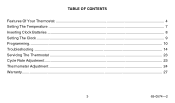
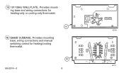
.... 2 THERMOSTAT COVER. Provides accurate room temperature reading. 4 CLOCK. Controls high and low temperature at specific time of day as set clock for 24-hour dial. 7 PROGRAM INDEX WHEEL. Left (blue mark) controls the low temperature, right (red mark) controls the high temperature. 1 2 3 M8726 69-0574-2 4 Features Of Your Thermostat 1 FLIP-UP COVER. wise to match the correct AM or PM time to set by program pins. 8 TEMPERATURE SETTING LEVERS. Turn minute hand clock- Lift it up and remove to hold...
.... 2 THERMOSTAT COVER. Provides accurate room temperature reading. 4 CLOCK. Controls high and low temperature at specific time of day as set clock for 24-hour dial. 7 PROGRAM INDEX WHEEL. Left (blue mark) controls the low temperature, right (red mark) controls the high temperature. 1 2 3 M8726 69-0574-2 4 Features Of Your Thermostat 1 FLIP-UP COVER. wise to match the correct AM or PM time to set by program pins. 8 TEMPERATURE SETTING LEVERS. Turn minute hand clock- Lift it up and remove to hold...
Owner's Manual
Page 5
... cooling system on 24-hour dial at 10-minute intervals for program pin insertion. 11 MANUAL PROGRAM ADVANCE BUTTON. Must be inserted into 24-hour clock dial slots to match the heating system primary control current. 14 MERCURY BULB AND BIMETAL ELEMENT (2). Must be adjusted to control program index wheel. 10 PIN SLOTS. Calibrated to energy savings setting and vice versa without changing the program. 12 HEAT ANTICIPATOR SCALEPLATE. 9 PROGRAM...
... cooling system on 24-hour dial at 10-minute intervals for program pin insertion. 11 MANUAL PROGRAM ADVANCE BUTTON. Must be inserted into 24-hour clock dial slots to match the heating system primary control current. 14 MERCURY BULB AND BIMETAL ELEMENT (2). Must be adjusted to control program index wheel. 10 PIN SLOTS. Calibrated to energy savings setting and vice versa without changing the program. 12 HEAT ANTICIPATOR SCALEPLATE. 9 PROGRAM...
Owner's Manual
Page 6
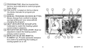
Provides mounting base and wiring connections for heating/cooling thermostat. 69-0574-2 16 6 M2421 R G FAN ON AUTO O B W Y HEAT COOL OFF M719 15 191108AJ WALLPLATE. Provides mounting base, wiring connections and manual switching control for heating-only or cooling-only thermostat. 15 16 Q682B SUBBASE.
Provides mounting base and wiring connections for heating/cooling thermostat. 69-0574-2 16 6 M2421 R G FAN ON AUTO O B W Y HEAT COOL OFF M719 15 191108AJ WALLPLATE. Provides mounting base, wiring connections and manual switching control for heating-only or cooling-only thermostat. 15 16 Q682B SUBBASE.

Owner's Manual
Page 7
... energy savings temperature you want when you are sleeping or your home is unoccupied. Set the right lever (red mark) to the temperature you want for normal comfort periods. Setting The Temperature For Heating: Set the left lever (blue mark) to the temperature you want for normal comfort periods. Set the right lever (red mark) to the same temperature set point. NOTE: You may override the time program by setting...
... energy savings temperature you want when you are sleeping or your home is unoccupied. Set the right lever (red mark) to the temperature you want for normal comfort periods. Setting The Temperature For Heating: Set the left lever (blue mark) to the temperature you want for normal comfort periods. Set the right lever (red mark) to the same temperature set point. NOTE: You may override the time program by setting...
Owner's Manual
Page 8
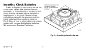
... alkaline batteries (included), or by the heating or cooling control circuit. Once a year or when batteries are dead, replace with two new AAA alkaline batteries. INSTALL WITH POSITIVE ENDS UP M7188 Fig. 2-Inserting clock batteries. 69-0574-2 8 BATTERY LOCATION FOR (2) AAA BATTERIES; We recommend Energizer® batteries. Install batteries in thermostat as shown in Fig. 2. Inserting Clock Batteries Power is supplied to the clock if power is interrupted when using 24 Vac powering method...
... alkaline batteries (included), or by the heating or cooling control circuit. Once a year or when batteries are dead, replace with two new AAA alkaline batteries. INSTALL WITH POSITIVE ENDS UP M7188 Fig. 2-Inserting clock batteries. 69-0574-2 8 BATTERY LOCATION FOR (2) AAA BATTERIES; We recommend Energizer® batteries. Install batteries in thermostat as shown in Fig. 2. Inserting Clock Batteries Power is supplied to the clock if power is interrupted when using 24 Vac powering method...
Owner's Manual
Page 10
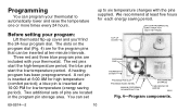
... inserted at 10:00 PM for low temperature (energy saving period). We recommend at 6:00 AM for each energy saving period. 24-HOUR PROGRAM DIAL (GRAY AREA FOR NIGHT SETTINGS) FLIP-UP COVER PROGRAM PINS THERMOSTAT COVER PROGRAM PIN SLOT PROGRAM INDEX WHEEL MANUAL PROGRAM ADVANCE BUTTON PROGRAM PIN STORAGE TIME INDICATOR ARROW M8692 Fig. 4-Program components. 69-0574-2 10 The red pins start the low-temperature period. A red pin is inserted at ten...
... inserted at 10:00 PM for low temperature (energy saving period). We recommend at 6:00 AM for each energy saving period. 24-HOUR PROGRAM DIAL (GRAY AREA FOR NIGHT SETTINGS) FLIP-UP COVER PROGRAM PINS THERMOSTAT COVER PROGRAM PIN SLOT PROGRAM INDEX WHEEL MANUAL PROGRAM ADVANCE BUTTON PROGRAM PIN STORAGE TIME INDICATOR ARROW M8692 Fig. 4-Program components. 69-0574-2 10 The red pins start the low-temperature period. A red pin is inserted at ten...

Owner's Manual
Page 11
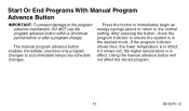
... PROGRAM TEMPERATURE PIN IN °F °C CONTROL 80 27 RED 75 24 BLUE 80 27 RED 75 24 BLUE M1690B Fig. 5-Programming examples. • You can set point. After the blue pin engages, the furnace will also probably want the energy savings period to start gives the furnace time to heat the house before this time. See Fig. 5 for program examples. 11 69-0574-2 Setting the Heating Program...
... PROGRAM TEMPERATURE PIN IN °F °C CONTROL 80 27 RED 75 24 BLUE 80 27 RED 75 24 BLUE M1690B Fig. 5-Programming examples. • You can set point. After the blue pin engages, the furnace will also probably want the energy savings period to start gives the furnace time to heat the house before this time. See Fig. 5 for program examples. 11 69-0574-2 Setting the Heating Program...
Owner's Manual
Page 13
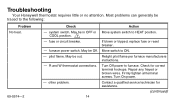
... the desired mode. if it shows red, the higher temperature is in effect. If the program indicator shows blue, the lower temperature is in effect; After pressing the button, check the program indicator to the normal setting. Start Or End Programs With Manual Program Advance Button IMPORTANT:To prevent damage to accommodate temporary schedule changes. The manual program advance button enables immediate, one-time-only program changes to the program advance mechanism, DO NOT use the program advance button within...
... the desired mode. if it shows red, the higher temperature is in effect. If the program indicator shows blue, the lower temperature is in effect; After pressing the button, check the program indicator to the normal setting. Start Or End Programs With Manual Program Advance Button IMPORTANT:To prevent damage to accommodate temporary schedule changes. The manual program advance button enables immediate, one-time-only program changes to the program advance mechanism, DO NOT use the program advance button within...
Owner's Manual
Page 14
... problem. R and W thermostat connections. Firmly tighten all terminal screws. Most problems can generally be in OFF or Move system switch to the following: Problem No heat. 69-0574-2 Check Action - fuse or circuit breaker. May be traced to HEAT position. Move switch to furnace. Turn On power. - Troubleshooting Your Honeywell thermostat requires little or no attention. COOL position. 1 - If blown or tripped, replace fuse or reset breaker. - Turn Off power to...
... problem. R and W thermostat connections. Firmly tighten all terminal screws. Most problems can generally be in OFF or Move system switch to the following: Problem No heat. 69-0574-2 Check Action - fuse or circuit breaker. May be traced to HEAT position. Move switch to furnace. Turn On power. - Troubleshooting Your Honeywell thermostat requires little or no attention. COOL position. 1 - If blown or tripped, replace fuse or reset breaker. - Turn Off power to...
Owner's Manual
Page 15
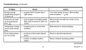
program dial for heating system. programs pins for correct time occurs at programmed May need more time to desired operating position. (continued) 15 69-0574-2 positions of subbase system switch. levers. - Move setting knob clockwise only. Reset to desired settings. Relocate pins to desired temperatures. Troubleshooting (continued) Problem Check Energy savings - timer program for proper day or temperature program night phase. 12 hours off. Move to warm up time. 2 rooms. Temperature change - Move red pin one...
program dial for heating system. programs pins for correct time occurs at programmed May need more time to desired operating position. (continued) 15 69-0574-2 positions of subbase system switch. levers. - Move setting knob clockwise only. Reset to desired settings. Relocate pins to desired temperatures. Troubleshooting (continued) Problem Check Energy savings - timer program for proper day or temperature program night phase. 12 hours off. Move to warm up time. 2 rooms. Temperature change - Move red pin one...

Owner's Manual
Page 16
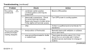
... does not operate, call a qualified technician. thermostat circuits. HEATING/COOLING SYSTEM-With system switch at HEAT, move temperature setting levers 5°F (3°C) above room temperature. Cooling system should start. Check - Heating system should start . (continued) 69-0574-2 16 Heating system should start . Action HEATING-ONLY SYSTEM-Move temperature setting levers 5°F (3°C) above room temperature. If the system does not operate, call a qualified technician. Troubleshooting (continued) Problem Room temperatures are...
... does not operate, call a qualified technician. thermostat circuits. HEATING/COOLING SYSTEM-With system switch at HEAT, move temperature setting levers 5°F (3°C) above room temperature. Cooling system should start. Check - Heating system should start . (continued) 69-0574-2 16 Heating system should start . Action HEATING-ONLY SYSTEM-Move temperature setting levers 5°F (3°C) above room temperature. If the system does not operate, call a qualified technician. Troubleshooting (continued) Problem Room temperatures are...

Owner's Manual
Page 17
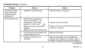
Troubleshooting (continued) Problem Room Temperatures are not correct (continued). anticipator setting. (See figure on page 23 for anticipator location.) - No cooling. 1 Check - anticipator setting. (See figure on page 23 for anticipator location.) - Cooling system should start. Burner-on time too short. system switch. fuse or circuit breaker. Decrease anticipator setting by 0.05. If fuse is blown or breaker tripped, replace or reset. (continued) 17 69-0574-2 If the...
Troubleshooting (continued) Problem Room Temperatures are not correct (continued). anticipator setting. (See figure on page 23 for anticipator location.) - No cooling. 1 Check - anticipator setting. (See figure on page 23 for anticipator location.) - Cooling system should start. Burner-on time too short. system switch. fuse or circuit breaker. Decrease anticipator setting by 0.05. If fuse is blown or breaker tripped, replace or reset. (continued) 17 69-0574-2 If the...
Owner's Manual
Page 18
... an inside wall. for assistance. - Contact a qualified service technician for correct terminal hookups. Thermostat should be turned OFF. Firmly tighten all terminal screws. - area around thermostat for change of thermostat. level position of location. (continued) 69-0574-2 18 Use a spirit level. - other. Contact qualified service technician for drafts or radiant heat. Troubleshooting (continued) Problem No cooling 1 (continued) Thermostat setting and thermometer reading disagree. Move to cooling system. Check Turn OFF power...
... an inside wall. for assistance. - Contact a qualified service technician for correct terminal hookups. Thermostat should be turned OFF. Firmly tighten all terminal screws. - area around thermostat for change of thermostat. level position of location. (continued) 69-0574-2 18 Use a spirit level. - other. Contact qualified service technician for drafts or radiant heat. Troubleshooting (continued) Problem No cooling 1 (continued) Thermostat setting and thermometer reading disagree. Move to cooling system. Check Turn OFF power...
Owner's Manual
Page 19
... connections, clock needs batteries in order to the table on page 24. Install as shown on page 8. Clock does not run . - thermostat connections at the two C terminals. Remove thermostat from the wallplate or subbase and measure the voltage. Check - calibration of thermometer. - Batteries may not have been installed. Replace thermostat. Troubleshooting (continued) Problem Thermostat setting and thermometer reading disagree (continued). if new batteries are installed and clock still does not run . Refer to run. 3 Batteries may need replacement - Replace with two new...
... connections, clock needs batteries in order to the table on page 24. Install as shown on page 8. Clock does not run . - thermostat connections at the two C terminals. Remove thermostat from the wallplate or subbase and measure the voltage. Check - calibration of thermometer. - Batteries may not have been installed. Replace thermostat. Troubleshooting (continued) Problem Thermostat setting and thermometer reading disagree (continued). if new batteries are installed and clock still does not run . Refer to run. 3 Batteries may need replacement - Replace with two new...

Owner's Manual
Page 20
... index wheel may be off power to make sure they are not completely seated in program dial. Troubleshooting (continued) Problem Clock does not run (continued). Push down on safety. - If clock powered Wire separate transformer to clock and equipment may occur. Replace filter and reset clock. (continued) 69-0574-2 20 power. high limit control. Clock loses time. power to power clock, or through system transformer, install backup batteries as shown on . Check Action...
... index wheel may be off power to make sure they are not completely seated in program dial. Troubleshooting (continued) Problem Clock does not run (continued). Push down on safety. - If clock powered Wire separate transformer to clock and equipment may occur. Replace filter and reset clock. (continued) 69-0574-2 20 power. high limit control. Clock loses time. power to power clock, or through system transformer, install backup batteries as shown on . Check Action...
Owner's Manual
Page 21
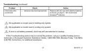
We recommend Energizer® batteries. 1 Not applicable on model used in heating-only system. 2 Not applicable on page 8. Action Replace with two new AAA alkaline batteries as shown on model used in cooling-only system. 3 If clock is not battery powered, clock may need replacement. Troubleshooting (continued) Problem Clock loses time (continued). Check - If this Troubleshooting section has not solved the problem, call your qualified heating service technician or Honeywell Customer Assistance Center, 1-800-468-1502...
We recommend Energizer® batteries. 1 Not applicable on model used in heating-only system. 2 Not applicable on page 8. Action Replace with two new AAA alkaline batteries as shown on model used in cooling-only system. 3 If clock is not battery powered, clock may need replacement. Troubleshooting (continued) Problem Clock loses time (continued). Check - If this Troubleshooting section has not solved the problem, call your qualified heating service technician or Honeywell Customer Assistance Center, 1-800-468-1502...
Owner's Manual
Page 22
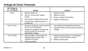
Free or replace limit switch. 4. Install transformer with subbase terminals. 2. used to ensure proper contact. 2. Restore power. 2. Replace wiring. 3. the clock is burned out. 2. Spring fingers o thermostat not making proper contact with proper secondary 2. Replace thermostat. 69-0574-2 22 Up to 15 Vac. 15 to power the clock has inadequate voltage. 1. Limit switch contacts stuck open. 4. Use additional (separate) transformer. System power off. 1. System transformer used to 30 Vac. Rebend spring...
Free or replace limit switch. 4. Install transformer with subbase terminals. 2. used to ensure proper contact. 2. Restore power. 2. Replace wiring. 3. the clock is burned out. 2. Spring fingers o thermostat not making proper contact with proper secondary 2. Replace thermostat. 69-0574-2 22 Up to 15 Vac. 15 to power the clock has inadequate voltage. 1. Limit switch contacts stuck open. 4. Use additional (separate) transformer. System power off. 1. System transformer used to 30 Vac. Rebend spring...

Owner's Manual
Page 23
Servicing The Thermostat Cycle Rate Adjustment The equipment should cycle on and off just enough to keep the room temperature close to cycle the heating system too fast or too slow, adjust the cycle rate by moving the anticipator setting lever one indicator mark at a time (Fig. 6). If the thermostat seems to the temperature lever settings. ANTICIPATOR SCALEPLATE ANTICIPATOR SETTING LEVER M7317 Fig. 6-Heat anticipator setting. 23 69-0574-2 NOTE: Most hot water systems require a setting of 1.2A. Observe the heating system operation after each adjustment.
Servicing The Thermostat Cycle Rate Adjustment The equipment should cycle on and off just enough to keep the room temperature close to cycle the heating system too fast or too slow, adjust the cycle rate by moving the anticipator setting lever one indicator mark at a time (Fig. 6). If the thermostat seems to the temperature lever settings. ANTICIPATOR SCALEPLATE ANTICIPATOR SETTING LEVER M7317 Fig. 6-Heat anticipator setting. 23 69-0574-2 NOTE: Most hot water systems require a setting of 1.2A. Observe the heating system operation after each adjustment.


