
Owner's Manual
Page 1
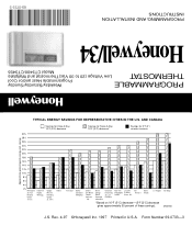
... cost savings TYPICAL ENERGY SAVINGS FOR REPRESENTATIVE CITIES IN THE U.S. Form Number 69-0733-3 69-0733-3 PROGRAMMING AND INSTALLATION INSTRUCTIONS Honeywell/34 Model CT3400/CT3455 THERMOSTAT Low Voltage (20 to 30 Vac)Thermostat and Wallplate PROGRAMMABLE Programmable Heat and/or Cool Weekday/Saturday/Sunday Approximate percentage of these savings). John's Halifax Vancouver Buffalo Cleveland...
... cost savings TYPICAL ENERGY SAVINGS FOR REPRESENTATIVE CITIES IN THE U.S. Form Number 69-0733-3 69-0733-3 PROGRAMMING AND INSTALLATION INSTRUCTIONS Honeywell/34 Model CT3400/CT3455 THERMOSTAT Low Voltage (20 to 30 Vac)Thermostat and Wallplate PROGRAMMABLE Programmable Heat and/or Cool Weekday/Saturday/Sunday Approximate percentage of these savings). John's Halifax Vancouver Buffalo Cleveland...

Owner's Manual
Page 2
...old control in the trash. Typical location of energy and money by the time you wake up or return home. Contact your new Honeywell Thermostat. TOTAL COMFORT TEMPERATURE MANAGEMENT WITH ADAPTIVE INTELLIGENT RECOVERY™ Congratulations! It comes already programmed, so it answers many of the questions ...that contains mercury in a sealed tube, do not place your Honeywell thermostat, the state of an old control containing mercury in home comfort controls. We invite you leave home or go on to have questions,...
...old control in the trash. Typical location of energy and money by the time you wake up or return home. Contact your new Honeywell Thermostat. TOTAL COMFORT TEMPERATURE MANAGEMENT WITH ADAPTIVE INTELLIGENT RECOVERY™ Congratulations! It comes already programmed, so it answers many of the questions ...that contains mercury in a sealed tube, do not place your Honeywell thermostat, the state of an old control containing mercury in home comfort controls. We invite you leave home or go on to have questions,...
Owner's Manual
Page 3
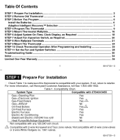
... Assistance, toll-free 1-800-468-1502. Table 1. Not compatible with 2-wire Honeywell and Taco zone valves. If not, return to make sure this thermostat is compatible with your system. System Type Compatible with CT3400/3455 Gas-Standing Pilot Gas-Electronic Ignition Gas-Fired Boilers Gas..., as Required 18 STEP 7 Adjust Fan Operation Switch, as Required 20 STEP 8 Wire Wallplate Terminals 21 STEP 9 Mount The Thermostat 24 STEP 10 Check Thermostat Operation After Programming and Installing 25 STEP 11 Set the Fan and System Switches 28 Troubleshooting Guide ...30 Index ...34 Limited One-...
... Assistance, toll-free 1-800-468-1502. Table 1. Not compatible with 2-wire Honeywell and Taco zone valves. If not, return to make sure this thermostat is compatible with your system. System Type Compatible with CT3400/3455 Gas-Standing Pilot Gas-Electronic Ignition Gas-Fired Boilers Gas..., as Required 18 STEP 7 Adjust Fan Operation Switch, as Required 20 STEP 8 Wire Wallplate Terminals 21 STEP 9 Mount The Thermostat 24 STEP 10 Check Thermostat Operation After Programming and Installing 25 STEP 11 Set the Fan and System Switches 28 Troubleshooting Guide ...30 Index ...34 Limited One-...

Owner's Manual
Page 4
... as needed (below 50°F (10°C). If it with the old terminal designation. s Disconnect wires from the old thermostat. If there are replacing a Honeywell Chronotherm® Thermostat, you may find one or two wires that go to keep them from the bottom, check for a screw used to lock... on the Chronotherm® Thermostat wiring wallplate. WALL OPENING Wrap wires around pencil to the C or C1 clock terminals on the...
... as needed (below 50°F (10°C). If it with the old terminal designation. s Disconnect wires from the old thermostat. If there are replacing a Honeywell Chronotherm® Thermostat, you may find one or two wires that go to keep them from the bottom, check for a screw used to lock... on the Chronotherm® Thermostat wiring wallplate. WALL OPENING Wrap wires around pencil to the C or C1 clock terminals on the...
Owner's Manual
Page 5
... where they will flash for 1 to 2 months before batteries run out completely. In this thermostat will be installed for heating only and can damage your system, call Honeywell Customer Assistance at 1-800-468-1502. If you do not wrap them together. Disconnect the wires... Six or more wires (excluding clock wires attached to terminals), you most likely have to reprogram the thermostat. s Install the batteries in chart on these systems. For details, call Honeywell Customer Assistance at 1-800-468-1502. 5 69-0733-3 STEP 3 Before You Program Install the Batteries...
... where they will flash for 1 to 2 months before batteries run out completely. In this thermostat will be installed for heating only and can damage your system, call Honeywell Customer Assistance at 1-800-468-1502. If you do not wrap them together. Disconnect the wires... Six or more wires (excluding clock wires attached to terminals), you most likely have to reprogram the thermostat. s Install the batteries in chart on these systems. For details, call Honeywell Customer Assistance at 1-800-468-1502. 5 69-0733-3 STEP 3 Before You Program Install the Batteries...
Owner's Manual
Page 6
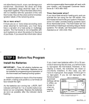
...to the weather, your lifestyle, home construction and heating/cooling system. Adaptive Intelligent Recovery™ Selection Before you program your thermostat, you must decide if you leave to prevent system from shutting down due to start of the time your furnace or ... Energizer® batteries. This smart control learns from experience. With conventional recovery, the programmed time marks the start recovery; INDICATES THERMOSTAT IS SET FOR CONVENTIONAL RECOVERY mostat display as the seasons change batteries before reaching your comfort time to be earlier than a month...
...to the weather, your lifestyle, home construction and heating/cooling system. Adaptive Intelligent Recovery™ Selection Before you program your thermostat, you must decide if you leave to prevent system from shutting down due to start of the time your furnace or ... Energizer® batteries. This smart control learns from experience. With conventional recovery, the programmed time marks the start recovery; INDICATES THERMOSTAT IS SET FOR CONVENTIONAL RECOVERY mostat display as the seasons change batteries before reaching your comfort time to be earlier than a month...
Owner's Manual
Page 7
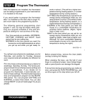
... and continue again at a comfortable temperature for activities before it (see page 15), as you would prefer to program the thermostat after it automatically controls to this programming section. The factory-preprogrammed time and temperature settings are shown in the times and temperatures...the ball of sharp fingernails or pencil points can program DAYTIME and EVENING, or leave them blank. PROGRAMMING 10 69-0733-3 The thermostat requires a time and temperature program for each. Before programming, remove the clear plastic overlay covering the display. Each period has its...
... and continue again at a comfortable temperature for activities before it (see page 15), as you would prefer to program the thermostat after it automatically controls to this programming section. The factory-preprogrammed time and temperature settings are shown in the times and temperatures...the ball of sharp fingernails or pencil points can program DAYTIME and EVENING, or leave them blank. PROGRAMMING 10 69-0733-3 The thermostat requires a time and temperature program for each. Before programming, remove the clear plastic overlay covering the display. Each period has its...

Owner's Manual
Page 9
.... Repeat steps as you did for SAT. 13 69-0733-3 COOLING PROGRAM The times you only need to start the program. When programming your new thermostat, use Temp a to SAT. SET PRESENT TIME Press and release Set Present Day/Time then a Time until present day shows. For Saturday, press Day a to...
.... Repeat steps as you did for SAT. 13 69-0733-3 COOLING PROGRAM The times you only need to start the program. When programming your new thermostat, use Temp a to SAT. SET PRESENT TIME Press and release Set Present Day/Time then a Time until present day shows. For Saturday, press Day a to...
Owner's Manual
Page 10
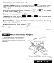
... indicator shows on display; Hold Temp on display, and cancels itself at next scheduled change. Return to move number ahead. 15 69-0733-3 STEP 5 Mount Thermostat Wallplate s Position wallplate on to normal program or start program- Cancel a program-Press and hold Daytime , or Evening Night three seconds to move number back...
... indicator shows on display; Hold Temp on display, and cancels itself at next scheduled change. Return to move number ahead. 15 69-0733-3 STEP 5 Mount Thermostat Wallplate s Position wallplate on to normal program or start program- Cancel a program-Press and hold Daytime , or Evening Night three seconds to move number back...

Owner's Manual
Page 11
... in, 1B- Gently tap anchors (provided) into holes. LEVEL M611B 17 69-0733-3 STEP 6 Adjust System On-Time, Clock Display, As Required s The thermostat on -time should be adjusted accordingly by setting screws 1A and 1B on -time, readjust screws 1A and/or 1B as a guide. The system on...system, the ontime must be optimized with the wall. First, turn . In the unlikely event that you are installing it on another type of the thermostat, using the heating system table in the illustration as follows: 18 69-0733-3 INSTALLATION s Remove wallplate from wall, and drill 3/16 inch holes ...
... in, 1B- Gently tap anchors (provided) into holes. LEVEL M611B 17 69-0733-3 STEP 6 Adjust System On-Time, Clock Display, As Required s The thermostat on -time should be adjusted accordingly by setting screws 1A and 1B on -time, readjust screws 1A and/or 1B as a guide. The system on...system, the ontime must be optimized with the wall. First, turn . In the unlikely event that you are installing it on another type of the thermostat, using the heating system table in the illustration as follows: 18 69-0733-3 INSTALLATION s Remove wallplate from wall, and drill 3/16 inch holes ...
Owner's Manual
Page 12
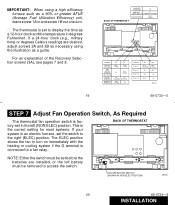
...setting for most systems. If your system is connected to display the time as a 12-hour clock and the temperature in degrees Fahrenheit. BACK OF THERMOSTAT NOTE: Either the switch must be set the switch to access the switch. FAN OPERATION SWITCH (SHOWN IN NON ELEC POSITION) M619C 20 69-0733..../ °C 2A 2B OUT OUT (FACTORY SETTING) IN OUT IN IN OUT IN M 618A 69-0733-3 STEP 7 Adjust Fan Operation Switch, As Required s The thermostat fan operation switch is set in and screw 1B out one turn on immediately with the heating or cooling system if the G terminal is an...
...setting for most systems. If your system is connected to display the time as a 12-hour clock and the temperature in degrees Fahrenheit. BACK OF THERMOSTAT NOTE: Either the switch must be set the switch to access the switch. FAN OPERATION SWITCH (SHOWN IN NON ELEC POSITION) M619C 20 69-0733..../ °C 2A 2B OUT OUT (FACTORY SETTING) IN OUT IN IN OUT IN M 618A 69-0733-3 STEP 7 Adjust Fan Operation Switch, As Required s The thermostat fan operation switch is set in and screw 1B out one turn on immediately with the heating or cooling system if the G terminal is an...

Owner's Manual
Page 13
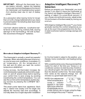
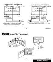
... jumper connect- Either straight or wraparound wiring connections are acceptable (see illustration). Refer to help prevent drafts from adversely affecting thermostat operation. STRIP 5/16 IN. (8MM) FOR WRAPAROUND- M612A HEATING RELAY OR VALVE COIL FAN RELAY COOLING CONTACTOR COIL 1... M2486 ing terminals R and Rc. 21 69-0733-3 2-WIRE HEAT-ONLY (JUMPER INTACT) W G R RC Y THERMOSTAT 4-WIRE HEAT/COOL (JUMPER INTACT) W G R RC Y THERMOSTAT HEATING RELAY OR VALVE COIL 1 1 POWER SUPPLY. Tighten terminals. STEP 8 Wire Wallplate Terminals NOTE: All wiring must...
... jumper connect- Either straight or wraparound wiring connections are acceptable (see illustration). Refer to help prevent drafts from adversely affecting thermostat operation. STRIP 5/16 IN. (8MM) FOR WRAPAROUND- M612A HEATING RELAY OR VALVE COIL FAN RELAY COOLING CONTACTOR COIL 1... M2486 ing terminals R and Rc. 21 69-0733-3 2-WIRE HEAT-ONLY (JUMPER INTACT) W G R RC Y THERMOSTAT 4-WIRE HEAT/COOL (JUMPER INTACT) W G R RC Y THERMOSTAT HEATING RELAY OR VALVE COIL 1 1 POWER SUPPLY. Tighten terminals. STEP 8 Wire Wallplate Terminals NOTE: All wiring must...
Owner's Manual
Page 14
...POWER SUPPLY. PROVIDE DISCONNECT MEANS AND OVERLOAD PROTECTION AS REQUIRED. PROVIDE DISCONNECT MEANS AND OVERLOAD PROTECTION AS REQUIRED. 1 M 615A 23 69-0733-3 STEP 9 Mount The Thermostat AM MON DAYTIME HEAT ON A. SWING COVER OPEN FOR CHECKOUT AND PROGRAMMING AM MON DAYTIME HEAT ON Set Present Day Time Hold Temp Day Morning... Evening Time Heat On Cool 24 B. PRESS LOWER EDGE OF CASE TO LATCH M5143 69-0733-3 INSTALLATION ENGAGE TABS BETWEEN TOP OF THERMOSTAT AND WALLPLATE C. M613A HEATING RELAY OR VALVE COIL FAN RELAY COOLING CONTACTOR COIL 1 1 POWER SUPPLY.
...POWER SUPPLY. PROVIDE DISCONNECT MEANS AND OVERLOAD PROTECTION AS REQUIRED. PROVIDE DISCONNECT MEANS AND OVERLOAD PROTECTION AS REQUIRED. 1 M 615A 23 69-0733-3 STEP 9 Mount The Thermostat AM MON DAYTIME HEAT ON A. SWING COVER OPEN FOR CHECKOUT AND PROGRAMMING AM MON DAYTIME HEAT ON Set Present Day Time Hold Temp Day Morning... Evening Time Heat On Cool 24 B. PRESS LOWER EDGE OF CASE TO LATCH M5143 69-0733-3 INSTALLATION ENGAGE TABS BETWEEN TOP OF THERMOSTAT AND WALLPLATE C. M613A HEATING RELAY OR VALVE COIL FAN RELAY COOLING CONTACTOR COIL 1 1 POWER SUPPLY.
Owner's Manual
Page 15
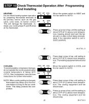
... operate the cooling system when outside temperature is Temp about 10°F (6°C) above room temperature. FAN ON AUTO This will damage the thermostat. HEAT FAN M2472 OFF COOL ON AUTO Press down arrow of key until setting is below room tempera- NOTE: When cooling setting is about...at the primary control, such as the gas valve, zone valve, oil burner control. Press up arrow of key until the setting is changed, thermostat may delay up arrow of key until the setting is about 10°F (6°C) above room tempera- This delay protects the compressor. STEP 10...
... operate the cooling system when outside temperature is Temp about 10°F (6°C) above room temperature. FAN ON AUTO This will damage the thermostat. HEAT FAN M2472 OFF COOL ON AUTO Press down arrow of key until setting is below room tempera- NOTE: When cooling setting is about...at the primary control, such as the gas valve, zone valve, oil burner control. Press up arrow of key until the setting is changed, thermostat may delay up arrow of key until the setting is about 10°F (6°C) above room tempera- This delay protects the compressor. STEP 10...

Owner's Manual
Page 16
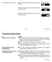
...The fan should run continuously. Use for improved air circulation during special occasions or for most homes. Exception: If fan operation switch on back of thermostat is in the AUTO position, fan cycles with the air conditioner or furnace. A twospeed fan usually runs on high with the air conditioner and...page 20), fan operates with the furnace. HEAT OFF COOL FAN ON AUTO Move the system switch to OFF and the fan switch to the thermostat.) FAN AUTO: Normal setting for more efficient electronic air cleaning. (In a heat-only system, fan runs continuously only if fan relay is connected...
...The fan should run continuously. Use for improved air circulation during special occasions or for most homes. Exception: If fan operation switch on back of thermostat is in the AUTO position, fan cycles with the air conditioner or furnace. A twospeed fan usually runs on high with the air conditioner and...page 20), fan operates with the furnace. HEAT OFF COOL FAN ON AUTO Move the system switch to OFF and the fan switch to the thermostat.) FAN AUTO: Normal setting for more efficient electronic air cleaning. (In a heat-only system, fan runs continuously only if fan relay is connected...
Owner's Manual
Page 17
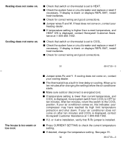
... not come on . Remove batteries. s You have reached the temperature setting limit. Be sure that AM and PM indications are off. HEAT: The thermostat controls your air conditioning system. s Make sure batteries are correct. Do not use anything abrasive on the clips. The setting range is 45°F to...176;C to OFF. Reprogram if necessary. HEAT OFF COOL 29 69-0733-3 Troubleshooting Guide IF... Temperature change occurs at least five seconds to reset thermostat. s Set the system switch to 31°C). s Check the program times for at the wrong times. HEAT OFF COOL COOL: The...
... not come on . Remove batteries. s You have reached the temperature setting limit. Be sure that AM and PM indications are off. HEAT: The thermostat controls your air conditioning system. s Make sure batteries are correct. Do not use anything abrasive on the clips. The setting range is 45°F to...176;C to OFF. Reprogram if necessary. HEAT OFF COOL 29 69-0733-3 Troubleshooting Guide IF... Temperature change occurs at least five seconds to reset thermostat. s Set the system switch to 31°C). s Check the program times for at the wrong times. HEAT OFF COOL COOL: The...
Owner's Manual
Page 18
...display is blank or displays REPL BAT, install fresh batteries. s Jumper wires Rc and Y. or 4-wire installation, verify that switch on thermostat is set to ten minutes after ten minutes and COOL is installed. See page 15. 32 69-0733-3 Heating does not come on ,... switch from COOL to check the current temperature setting. s Check that R-Rc jumper is displayed, contact Honeywell Customer Assistance at 1-800-468-1502. s Jumper wires R and W. s Check that switch on thermostat is set to the COOL position. s Check for ten minutes. Cooling does not come on ). ...
...display is blank or displays REPL BAT, install fresh batteries. s Jumper wires Rc and Y. or 4-wire installation, verify that switch on thermostat is set to ten minutes after ten minutes and COOL is installed. See page 15. 32 69-0733-3 Heating does not come on ,... switch from COOL to check the current temperature setting. s Check that R-Rc jumper is displayed, contact Honeywell Customer Assistance at 1-800-468-1502. s Jumper wires R and W. s Check that switch on thermostat is set to the COOL position. s Check for ten minutes. Cooling does not come on ). ...
Owner's Manual
Page 19
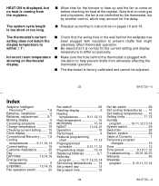
... short or too long. s Allow time for the furnace to heat up and the fan to come on pages 18 and 19. The thermostat's current setting does not match the display temperature to instructions on before checking for the current setting and display temperature to differ occasionally. s ...Check that the wiring hole in the wall behind the thermostat is plugged with insulation to help prevent drafts from the registers. Incorrect room temperature s Make sure the hole behind the wallplate has been ...
... short or too long. s Allow time for the furnace to heat up and the fan to come on pages 18 and 19. The thermostat's current setting does not match the display temperature to instructions on before checking for the current setting and display temperature to differ occasionally. s ...Check that the wiring hole in the wall behind the thermostat is plugged with insulation to help prevent drafts from the registers. Incorrect room temperature s Make sure the hole behind the wallplate has been ...
Owner's Manual
Page 20
...of a consumer. If the product is defective or malfunctions, Honeywell shall repair or replace it , with Canadian Radio Interference Regulations, CRC c.1374. 35 69-0733-3 Limited One-Year Warranty Honeywell warrants this thermostat, please read and follow the instructions. This warranty gives ...you specific legal rights, and you may not apply to you call Honeywell Customer Assistance toll-free at Honeywell's option) within the terms stated...
...of a consumer. If the product is defective or malfunctions, Honeywell shall repair or replace it , with Canadian Radio Interference Regulations, CRC c.1374. 35 69-0733-3 Limited One-Year Warranty Honeywell warrants this thermostat, please read and follow the instructions. This warranty gives ...you specific legal rights, and you may not apply to you call Honeywell Customer Assistance toll-free at Honeywell's option) within the terms stated...


