Installation Instructions
Page 1
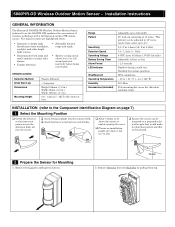
...0.3 - 1.5m/s (1 - 5ft/s) 6 VDC (uses 4 lithium 1.5VDC AA cells) Adjustable 120sec or 5sec ~ 2.5 seconds Enabled during a walk test. Remove the Cover by pulling from bottom. Parallel 2. Remove Detector from the Back Box by pulling from top. SPECIFICATIONS Detection Method Initial Warm Up Dimensions...bright light sources. ƒ Discriminates both large and small animals to as the 5800PIR-OD) combines the convenience of lens. Installation Instructions GENERAL INFORMATION The Honeywell 5800PIR-OD Wireless Outdoor Motion Sensor (referred to reduce false alarms. ƒ Tamper ...
...0.3 - 1.5m/s (1 - 5ft/s) 6 VDC (uses 4 lithium 1.5VDC AA cells) Adjustable 120sec or 5sec ~ 2.5 seconds Enabled during a walk test. Remove the Cover by pulling from bottom. Parallel 2. Remove Detector from the Back Box by pulling from top. SPECIFICATIONS Detection Method Initial Warm Up Dimensions...bright light sources. ƒ Discriminates both large and small animals to as the 5800PIR-OD) combines the convenience of lens. Installation Instructions GENERAL INFORMATION The Honeywell 5800PIR-OD Wireless Outdoor Motion Sensor (referred to reduce false alarms. ƒ Tamper ...
Installation Instructions
Page 2
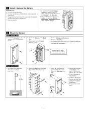
Fasten with the M3 x 10 Captive Lock Screw. 7. Perform a Walk Test. 6. POLE MOUNTING 1. Use a pole with an outside diameter of battery is pointing away from the springs. 4 Mount the Sensor WALL MOUNTING 1. Perform Settings & Adjustments. 6. Observe... L91 or equivalent.) ƒ Change all four batteries at the same time. UP 4. If necessary, loosen the Captive Lock Screw and lift Cover off. Perform a Walk Test. 7. Perform Settings & Adjustments. 5. Secure the Cover with new batteries. ƒ Observe polarity. 1. Using the Pole Brackets and four M4 x 30 screws, fasten the Back ...
Fasten with the M3 x 10 Captive Lock Screw. 7. Perform a Walk Test. 6. POLE MOUNTING 1. Use a pole with an outside diameter of battery is pointing away from the springs. 4 Mount the Sensor WALL MOUNTING 1. Perform Settings & Adjustments. 6. Observe... L91 or equivalent.) ƒ Change all four batteries at the same time. UP 4. If necessary, loosen the Captive Lock Screw and lift Cover off. Perform a Walk Test. 7. Perform Settings & Adjustments. 5. Secure the Cover with new batteries. ƒ Observe polarity. 1. Using the Pole Brackets and four M4 x 30 screws, fasten the Back ...
Installation Instructions
Page 4
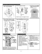
Separate the Lens from the Cover. Use for 5 or 120 seconds. 120s - Set switch 1 to enable the Walk Test, then perform the walk test on the Lens to remove the Lens Holder. 2. Battery Saving Timer 2 3. IF NECESSARY, CONFIGURE DETECTION MASKING 1. Lens Holder.... Ensure the Lens Holder is required. Sensitivity Select Switch (Low, Med, High) DIP Switches Default Setting Low Sensitivity - Default Setting 5s - Walk Test 5s 2. Set switch 3 for the desired Pulse Count (selectable for the desired Battery Saving Timer period. High sensitivity - Pulse Count of 4 ...
Separate the Lens from the Cover. Use for 5 or 120 seconds. 120s - Set switch 1 to enable the Walk Test, then perform the walk test on the Lens to remove the Lens Holder. 2. Battery Saving Timer 2 3. IF NECESSARY, CONFIGURE DETECTION MASKING 1. Lens Holder.... Ensure the Lens Holder is required. Sensitivity Select Switch (Low, Med, High) DIP Switches Default Setting Low Sensitivity - Default Setting 5s - Walk Test 5s 2. Set switch 3 for the desired Pulse Count (selectable for the desired Battery Saving Timer period. High sensitivity - Pulse Count of 4 ...
Installation Instructions
Page 5
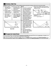
...alarm is generated instantly. 1. 6 Perform a Walk Test NOTE: With the Walk Test switch set to your desired setting. - 5 - Then perform a walk test to verify satisfactory results. 7 Program the Control Panel Prior to use the Walk Test setting or temporally set to the control panel's...position "B". If necessary, adjust the detection area (see Perform Settings & Adjustments). 5. Perform a walk test through the detection area, and verify satisfactory results. 6. Repeat the walk test through the detection area, and verify satisfactory results. 3. Notes: ƒ If normal car or ...
...alarm is generated instantly. 1. 6 Perform a Walk Test NOTE: With the Walk Test switch set to your desired setting. - 5 - Then perform a walk test to verify satisfactory results. 7 Program the Control Panel Prior to use the Walk Test setting or temporally set to the control panel's...position "B". If necessary, adjust the detection area (see Perform Settings & Adjustments). 5. Perform a walk test through the detection area, and verify satisfactory results. 6. Repeat the walk test through the detection area, and verify satisfactory results. 3. Notes: ƒ If normal car or ...


