Installation Instructions
Page 1
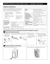
... reactivated. Range Pattern Sensitivity Detection Speed Operating Voltage Battery Saving Timer Alarm Period LED Indicator Weatherproof Operating Temperature Humidity Accessories (included) Adjustable up to 12m (40ft) 90° pattern consisting of lens. Disabled for a 5 or 120 second period of wireless technology with a full featured outdoor PIR motion sensor. Parallel 2. Remove Detector from the Back Box by pulling from top. 5800PIR-OD Wireless Outdoor Motion Sensor - This pattern...
... reactivated. Range Pattern Sensitivity Detection Speed Operating Voltage Battery Saving Timer Alarm Period LED Indicator Weatherproof Operating Temperature Humidity Accessories (included) Adjustable up to 12m (40ft) 90° pattern consisting of lens. Disabled for a 5 or 120 second period of wireless technology with a full featured outdoor PIR motion sensor. Parallel 2. Remove Detector from the Back Box by pulling from top. 5800PIR-OD Wireless Outdoor Motion Sensor - This pattern...
Installation Instructions
Page 2
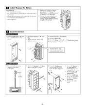
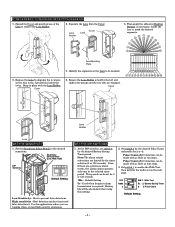
... that secure the Detector to reveal the screw holes. Perform Settings & Adjustments. 5. Observe the proper polarity and replace the batteries. Perform a Walk Test. 6. Secure the Detector to the Back Box with an outside diameter of battery is pointing away from the springs. 4 Mount the Sensor WALL MOUNTING 1. Perform a Walk Test. 7. Secure the Cover with four selftapping M3 x 14 screws. 5. Program the control panel. Install the Back Box on the wall using...
... that secure the Detector to reveal the screw holes. Perform Settings & Adjustments. 5. Observe the proper polarity and replace the batteries. Perform a Walk Test. 6. Secure the Detector to the Back Box with an outside diameter of battery is pointing away from the springs. 4 Mount the Sensor WALL MOUNTING 1. Perform a Walk Test. 7. Secure the Cover with four selftapping M3 x 14 screws. 5. Program the control panel. Install the Back Box on the wall using...
Installation Instructions
Page 3
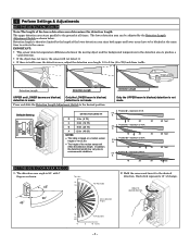
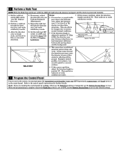
... Adjustable Active detection fingers. 2. Adjust to be blocked at all times. 5 Perform Settings & Adjustments SET THE DETECTION LENGTH Note: The length of 40 ft. The upper detection area stays parallel to the ground at the same time to the desired direction. Detection length is made . Position D - maximum of the lower detection area determines the detection length. maximum of the motion sensor will not detect it to activate the sensor. Default Setting D C B A DETECTION...
... Adjustable Active detection fingers. 2. Adjust to be blocked at all times. 5 Perform Settings & Adjustments SET THE DETECTION LENGTH Note: The length of 40 ft. The upper detection area stays parallel to the ground at the same time to the desired direction. Detection length is made . Position D - maximum of the lower detection area determines the detection length. maximum of the motion sensor will not detect it to activate the sensor. Default Setting D C B A DETECTION...
Installation Instructions
Page 4
... enable the Walk Test, then perform the walk test on the lens to the 4 projections inside the lens to be shortened when using this setting. 2. Sensitivity Select Switch (Low, Med, High) DIP Switches Default Setting Low Sensitivity - SET THE DIP SWITCHES 1. Cover 6. Best detection catches (increased false detections). Note: The alarm output activations are tagging video, or need high security awareness. ON 123 OFF 120s 4 ON 1. Battery Saving Timer...
... enable the Walk Test, then perform the walk test on the lens to the 4 projections inside the lens to be shortened when using this setting. 2. Sensitivity Select Switch (Low, Med, High) DIP Switches Default Setting Low Sensitivity - SET THE DIP SWITCHES 1. Cover 6. Best detection catches (increased false detections). Note: The alarm output activations are tagging video, or need high security awareness. ON 123 OFF 120s 4 ON 1. Battery Saving Timer...
Installation Instructions
Page 5
... LED will light when the detector is tripped, and the alarm is set the Battery Saving Timer to ON. Examples include puddles, wet surfaces, very smooth asphalt or concrete surfaces. ƒ If this causes a problem, adjust the detection length to issue a false alarm by walking, either use in the control panel. When the programming is complete ensure the Walk Test switch is set to OFF...
... LED will light when the detector is tripped, and the alarm is set the Battery Saving Timer to ON. Examples include puddles, wet surfaces, very smooth asphalt or concrete surfaces. ƒ If this causes a problem, adjust the detection length to issue a false alarm by walking, either use in the control panel. When the programming is complete ensure the Walk Test switch is set to OFF...
Installation Instructions
Page 6
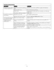
... heat, or shorten the Detection Length. - 6 - Replace batteries. Move or remove the heat source. Sensor is detecting moving trees, or bushes or a strong light source. TROUBLESHOOTING SYMPTOM CAUSE No detection, when walking through the detection area. Batteries are very low or dead. Wiring is parallel to the source of light. Sensitivity is not set too low. Try a higher sensitivity setting. Replace unit. Detection area is set correctly. Check all connectors...
... heat, or shorten the Detection Length. - 6 - Replace batteries. Move or remove the heat source. Sensor is detecting moving trees, or bushes or a strong light source. TROUBLESHOOTING SYMPTOM CAUSE No detection, when walking through the detection area. Batteries are very low or dead. Wiring is parallel to the source of light. Sensitivity is not set too low. Try a higher sensitivity setting. Replace unit. Detection area is set correctly. Check all connectors...
Installation Instructions
Page 7
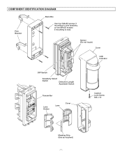
UP Sensor (Do not touch) Cover LED Indicator DIP Switch Sensitivity Select Switch Detection Length Ajustment Switch Transmitter Lens Holder Lens Cover Captive Lock Screw M3 x 10 Masking Strip (Use as required) - 7 - COMPONENT IDENTIFICATION DIAGRAM Pole Bracket Back Box Use four M4x30 screws if mounting to pole brackets, or two M4x20 screws if mounting to wall.
UP Sensor (Do not touch) Cover LED Indicator DIP Switch Sensitivity Select Switch Detection Length Ajustment Switch Transmitter Lens Holder Lens Cover Captive Lock Screw M3 x 10 Masking Strip (Use as required) - 7 - COMPONENT IDENTIFICATION DIAGRAM Pole Bracket Back Box Use four M4x30 screws if mounting to pole brackets, or two M4x20 screws if mounting to wall.
Installation Instructions
Page 8
... / IC STATEMENT This device complies with Part 15 of the FCC Rules, and RSS210 of IC. www.honeywell.com/security ÊK15009V2>Š K15009V2 2/10 Rev. INFORMATION TO USER Unauthorized changes or modifications could void the user's authority to : http://www.security.honeywell.com/hsc/resources/wa/ 2 Corporate Center Drive, Suite 100 P.O. Operation is subject to the following conditions...
... / IC STATEMENT This device complies with Part 15 of the FCC Rules, and RSS210 of IC. www.honeywell.com/security ÊK15009V2>Š K15009V2 2/10 Rev. INFORMATION TO USER Unauthorized changes or modifications could void the user's authority to : http://www.security.honeywell.com/hsc/resources/wa/ 2 Corporate Center Drive, Suite 100 P.O. Operation is subject to the following conditions...


