

User Guide
Page 13
Plug and Play 2-1 Keyboard Wedge 2-1 Laptop Direct Connect 2-1 RS232 Serial Port 2-2 RS485 2-2 RS485 Packet Mode 2-3 USB IBM SurePos 2-4 USB PC or Macintosh Keyboard 2-4 USB HID 2-5 USB Serial 2-5 Verifone® Ruby Terminal Default Settings 2-6 Gilbarco® Terminal Default Settings 2-7 Honeywell Bioptic Aux Port Configuration 2-7 Datalogic™ Magellan© Bioptic Aux Port Configuration 2-7 NCR Bioptic Aux Port Configuration...
Plug and Play 2-1 Keyboard Wedge 2-1 Laptop Direct Connect 2-1 RS232 Serial Port 2-2 RS485 2-2 RS485 Packet Mode 2-3 USB IBM SurePos 2-4 USB PC or Macintosh Keyboard 2-4 USB HID 2-5 USB Serial 2-5 Verifone® Ruby Terminal Default Settings 2-6 Gilbarco® Terminal Default Settings 2-7 Honeywell Bioptic Aux Port Configuration 2-7 Datalogic™ Magellan© Bioptic Aux Port Configuration 2-7 NCR Bioptic Aux Port Configuration...
User Guide
Page 21
...-1 1902 Scanner Product Specifications 12-2 CCB01-010BT Charge Base Product Specifications 12-3 Standard Cable Pinouts 12-4 Keyboard Wedge 12-4 Serial Output 12-5 RS485 Output 12-6 USB 12-7 Chapter 13 -
...-1 1902 Scanner Product Specifications 12-2 CCB01-010BT Charge Base Product Specifications 12-3 Standard Cable Pinouts 12-4 Keyboard Wedge 12-4 Serial Output 12-5 RS485 Output 12-6 USB 12-7 Chapter 13 -

User Guide
Page 24
Connect the appropriate interface cable to the device first, then to the USB port of a computer. 1. Corded Scanner USB Connection: Cordless Base USB Connection: 1 - 2 Connecting the Device Connecting with USB A scanner or a cordless base can be connected to the computer.
Connect the appropriate interface cable to the device first, then to the USB port of a computer. 1. Corded Scanner USB Connection: Cordless Base USB Connection: 1 - 2 Connecting the Device Connecting with USB A scanner or a cordless base can be connected to the computer.
User Guide
Page 25
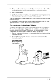
Connect the appropriate interface cable to the device and to page 2-4 for other USB terminal settings. Corded Scanner Keyboard Wedge Connection: 1 - 3 Make sure the cables are secured in the wireways in the bottom of a keyboard wedge connection: 1....the cordless base and that the base sits flat on a horizontal surface. 3. The scanner beeps. 4. For additional USB programming and technical information, refer to a USB PC Keyboard. The unit defaults to "USB Application Note," available at www.honeywellaidc.com. Turn off power and disconnect the keyboard cable from the Sample Symbols...
Connect the appropriate interface cable to the device and to page 2-4 for other USB terminal settings. Corded Scanner Keyboard Wedge Connection: 1 - 3 Make sure the cables are secured in the wireways in the bottom of a keyboard wedge connection: 1....the cordless base and that the base sits flat on a horizontal surface. 3. The scanner beeps. 4. For additional USB programming and technical information, refer to a USB PC Keyboard. The unit defaults to "USB Application Note," available at www.honeywellaidc.com. Turn off power and disconnect the keyboard cable from the Sample Symbols...

User Guide
Page 36
...0D 0B 00 18 0B 00 0A 0B USB PC or Macintosh Keyboard Scan one of the following codes to program the scanner for USB PC Keyboard or USB Macintosh Keyboard. USB Keyboard (PC) USB Japanese Keyboard (PC) USB Keyboard (Mac) 2 - 4 USB IBM SurePos Scan one of the following "...Plug and Play" codes to program the scanner for an IBM SurePos (USB handheld scanner) or IBM SurePos (USB tabletop scanner) interface...
...0D 0B 00 18 0B 00 0A 0B USB PC or Macintosh Keyboard Scan one of the following codes to program the scanner for USB PC Keyboard or USB Macintosh Keyboard. USB Keyboard (PC) USB Japanese Keyboard (PC) USB Keyboard (Mac) 2 - 4 USB IBM SurePos Scan one of the following "...Plug and Play" codes to program the scanner for an IBM SurePos (USB handheld scanner) or IBM SurePos (USB tabletop scanner) interface...

User Guide
Page 37
...scanners. The driver will need to emulate a regular RS232-based COM Port. Apple® Macintosh computers recognize the scanner as a USB CDC class device and automatically uses a class driver. USB Serial Note: No extra configuration (e.g., baud rate) is necessary. If you are using a Microsoft® Windows® PC,... you will use the next available COM Port number. CTS/RTS Emulation CTS/RTS Emulation On * CTS/RTS Emulation Off 2 - 5 USB HID Scan the following code to program the scanner to download a driver from the Honeywell website (www.honeywellaidc.com).
...scanners. The driver will need to emulate a regular RS232-based COM Port. Apple® Macintosh computers recognize the scanner as a USB CDC class device and automatically uses a class driver. USB Serial Note: No extra configuration (e.g., baud rate) is necessary. If you are using a Microsoft® Windows® PC,... you will use the next available COM Port number. CTS/RTS Emulation CTS/RTS Emulation On * CTS/RTS Emulation Off 2 - 5 USB HID Scan the following code to program the scanner to download a driver from the Honeywell website (www.honeywellaidc.com).

User Guide
Page 65
... LED Sequences and Meaning, page 3-7, for additional information. ! There is no need to charge a scanner without impacting the battery life. Caution: Use only Honeywell Li-ion battery packs, part number 100000495, rated 3.7 Vdc, 7.4Whr, in this type of battery. • Keep the base connected to power when ... the battery is unable to hold an adequate charge. • If you are powering the base through the interface cable (for example, a USB cable) and not using an external power supply plugged into the aux port, the current available for inspection. Place the scanner in damage not ...
... LED Sequences and Meaning, page 3-7, for additional information. ! There is no need to charge a scanner without impacting the battery life. Caution: Use only Honeywell Li-ion battery packs, part number 100000495, rated 3.7 Vdc, 7.4Whr, in this type of battery. • Keep the base connected to power when ... the battery is unable to hold an adequate charge. • If you are powering the base through the interface cable (for example, a USB cable) and not using an external power supply plugged into the aux port, the current available for inspection. Place the scanner in damage not ...

User Guide
Page 67
... detected or charge suspended Pre-charge and charging Charge complete Charge Error Green LED Off Slow flash, 1 second on, 1 second off 3 - 7 Host Communication Communication Condition USB suspend Power on , 300 mSec off On continuously Fast flash, 300 mSec on , system idle Receiving data Red or Blue LED Off On continuously Short...
... detected or charge suspended Pre-charge and charging Charge complete Charge Error Green LED Off Slow flash, 1 second on, 1 second off 3 - 7 Host Communication Communication Condition USB suspend Power on , 300 mSec off On continuously Fast flash, 300 mSec on , system idle Receiving data Red or Blue LED Off On continuously Short...

User Guide
Page 91
... requires it is recommended that command. The commands to create custom response sequences. Commands may be met for Host Port RS232 (terminal ID = 000) or USB COM Emulation (terminal ID = 130). • RTS/CTS is emitted until the scanner receives an escape command. The scanner read illumination goes out when there...
... requires it is recommended that command. The commands to create custom response sequences. Commands may be met for Host Port RS232 (terminal ID = 000) or USB COM Emulation (terminal ID = 130). • RTS/CTS is emitted until the scanner receives an escape command. The scanner read illumination goes out when there...

User Guide
Page 123
... code using the Programming Chart inside the back cover of this manual. User Specified Intercharacter Delay An intercharacter delay of up to 5000 milliseconds (in USB serial emulation. Delay Length Character to Trigger Delay bar code, then the 2-digit hex value for the ASCII character that will trigger the delay ASCII...
... code using the Programming Chart inside the back cover of this manual. User Specified Intercharacter Delay An intercharacter delay of up to 5000 milliseconds (in USB serial emulation. Delay Length Character to Trigger Delay bar code, then the 2-digit hex value for the ASCII character that will trigger the delay ASCII...

User Guide
Page 128
... xx stands for the the insert character's hex value for its ASCII code. Terminal ID Table Terminal Model(s) IBM RS232 RS485 USB PC/AT and compatibles USB SurePOS Handheld Scanner USB SurePOS Tabletop Scanner True TTL Serial PC Keyboard Mac Keyboard Japanese Keyboard (PC) HID POS Data Format Editor Commands Terminal ID 003...
... xx stands for the the insert character's hex value for its ASCII code. Terminal ID Table Terminal Model(s) IBM RS232 RS485 USB PC/AT and compatibles USB SurePOS Handheld Scanner USB SurePOS Tabletop Scanner True TTL Serial PC Keyboard Mac Keyboard Japanese Keyboard (PC) HID POS Data Format Editor Commands Terminal ID 003...

User Guide
Page 203
... for RS232) 4P Hmodem S - It addresses the protocol used to send the data (Hmodem, which is sent. 0P None (raw data) 2P None (default for USB) 3P Hmodem compressed (default for shipping an image. nM Margin: cut from the outside margin of the image; Range: 0 - 238. (Default = 0, or full image) Example...
... for RS232) 4P Hmodem S - It addresses the protocol used to send the data (Hmodem, which is sent. 0P None (raw data) 2P None (default for USB) 3P Hmodem compressed (default for shipping an image. nM Margin: cut from the outside margin of the image; Range: 0 - 238. (Default = 0, or full image) Example...

User Guide
Page 224
...to the c:\windows\temp directory. 10 - 4 The "Configure" tree option has all the image-related functions that can perform. Access the Honeywell web site at least one of the scanner. When using the serial port and RS232 cable, an external power supply is loaded with a .... You can be prompted to that the PC have at www.honeywellaidc.com 2. Imaging also lets you are using a USB serial port emulation, only a USB cable is displayed as required. Imaging Imaging provides all the programming and configuration parameters specified for a scanner. Click on the...
...to the c:\windows\temp directory. 10 - 4 The "Configure" tree option has all the image-related functions that can perform. Access the Honeywell web site at least one of the scanner. When using the serial port and RS232 cable, an external power supply is loaded with a .... You can be prompted to that the PC have at www.honeywellaidc.com 2. Imaging also lets you are using a USB serial port emulation, only a USB cable is displayed as required. Imaging Imaging provides all the programming and configuration parameters specified for a scanner. Click on the...

User Guide
Page 232
... IBM Port 9B HHBCR-2 Interface RS485 Packet Mode On RS485 Packet Mode Off RS485 Packet Length (20-256) USB IBM SurePos Handheld USB IBM SurePos Tabletop USB Keyboard (PC) USB Keyboard (Mac) USB Japanese Keyboard (PC) USB HID USB Serial CTS/RTS Emulation On CTS/RTS Emulation Off* ACK/NAK Mode On ACK/NAK Mode Off* Serial...
... IBM Port 9B HHBCR-2 Interface RS485 Packet Mode On RS485 Packet Mode Off RS485 Packet Length (20-256) USB IBM SurePos Handheld USB IBM SurePos Tabletop USB Keyboard (PC) USB Keyboard (Mac) USB Japanese Keyboard (PC) USB HID USB Serial CTS/RTS Emulation On CTS/RTS Emulation Off* ACK/NAK Mode On ACK/NAK Mode Off* Serial...

User Guide
Page 265
...; left JPEG Image Quality (0-100) *50 *Gamma Correction Off Gamma Correction On (0-1000) Image Crop - Right (0-640) *639 Image Crop - Hmodem Compressed Protocol - None (default USB) Protocol - Hmodem Ship Every Pixel Serial Command # Indicates a numeric entry IMGNVX1 IMGNVY1 IMGROT0 IMGROT1 IMGROT2 IMGROT3 IMGJQF### IMGGAM0 IMGGAM### IMGWNL### IMGWNR### IMGWNT### IMGWNB### IMGMAR### IMGXFR0...
...; left JPEG Image Quality (0-100) *50 *Gamma Correction Off Gamma Correction On (0-1000) Image Crop - Right (0-640) *639 Image Crop - Hmodem Compressed Protocol - None (default USB) Protocol - Hmodem Ship Every Pixel Serial Command # Indicates a numeric entry IMGNVX1 IMGNVY1 IMGROT0 IMGROT1 IMGROT2 IMGROT3 IMGJQF### IMGGAM0 IMGGAM### IMGWNL### IMGWNR### IMGWNT### IMGWNB### IMGMAR### IMGXFR0...

User Guide
Page 273
Use of a cable with Honeywell legacy products. Standard Cable Pinouts USB 12 - 7 10 Pin Modular Plug connects to the unit. Use of any cables not provided by the manufacturer may lead to damage to the base 1 Cable shield 2 Cable select 3 Supply ground 4 5 6 7 +5V power 8 9 Data + 10 Data - Note: Pin assignments are not compatible with improper pin assignments may result in damage not covered by your warranty.
Use of a cable with Honeywell legacy products. Standard Cable Pinouts USB 12 - 7 10 Pin Modular Plug connects to the unit. Use of any cables not provided by the manufacturer may lead to damage to the base 1 Cable shield 2 Cable select 3 Supply ground 4 5 6 7 +5V power 8 9 Data + 10 Data - Note: Pin assignments are not compatible with improper pin assignments may result in damage not covered by your warranty.


