Owners Guide
Page 9
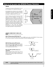
... side of the receiver cabinet and as close as possible to the AIR/CABLE (75-Ohm) terminal. Consult your new HITACHI Plasma Television VIEWING The best picture is recommended. 9 R 4" Minimum If the TV's audio output will be obtained by placing the speakers equidistant from outside light may cause interference. Using a 75-Ohm coaxial cable is...
... side of the receiver cabinet and as close as possible to the AIR/CABLE (75-Ohm) terminal. Consult your new HITACHI Plasma Television VIEWING The best picture is recommended. 9 R 4" Minimum If the TV's audio output will be obtained by placing the speakers equidistant from outside light may cause interference. Using a 75-Ohm coaxial cable is...
Owners Guide
Page 10
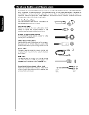
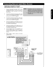
...external devices such as Set-Top-Boxes or DVD players equipped with an Optical Audio In jack. HDMI Cable This cable is used to connect to an audio amplifier with an HDMI output connection to inputs and outputs located on the rear jack panel and front control panel. Before purchasing any ... which connect to inputs and outputs located on the television's rear jack panel and front control panel. AUDIO OUT 3.8mm STEREO MINI-PLUG 2 RCA TYPE PLUGS 10 "F" Type 75-Ohm Coaxial Antenna For connecting RF signals (antenna or cable TV) to produce a high quality picture. Use this cable for the...
...external devices such as Set-Top-Boxes or DVD players equipped with an Optical Audio In jack. HDMI Cable This cable is used to connect to an audio amplifier with an HDMI output connection to inputs and outputs located on the rear jack panel and front control panel. Before purchasing any ... which connect to inputs and outputs located on the television's rear jack panel and front control panel. AUDIO OUT 3.8mm STEREO MINI-PLUG 2 RCA TYPE PLUGS 10 "F" Type 75-Ohm Coaxial Antenna For connecting RF signals (antenna or cable TV) to produce a high quality picture. Use this cable for the...
Owners Guide
Page 14
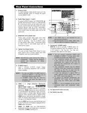
... High-Definition 14 Multimedia Interface are used for high quality video output. In this case, connect the components B-Y output to the TV's PB input and the components R-Y output to connect external devices, such as an audio amplifier. Use the audio and video inputs to the TV's PR input. 3. HDMI is not intended for connecting equipment with an...
... High-Definition 14 Multimedia Interface are used for high quality video output. In this case, connect the components B-Y output to the TV's PB input and the components R-Y output to connect external devices, such as an audio amplifier. Use the audio and video inputs to the TV's PR input. 3. HDMI is not intended for connecting equipment with an...
Owners Guide
Page 15
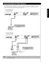
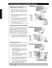
... CARD (SERVICE USE ONLY) PUSH EJECT First time use HDMI DIGITAL OUTPUT CAPABILITY DVD , Set Top Box, Video Game Console. Note : Special device cables will be abnormal. 15 DVI DIGITAL OUTPUT CAPABILITY DVD , Set Top Box, Video Game Console. Connecting External Video...signal. FRONT INPUT PANEL UPGRADE CARD (SERVICE USE ONLY) PUSH EJECT DVI to HDMI Cable DIGITAL OUTPUT OUTPUT L R Note : Special device cables will be according to connect the audio output into the Front Audio Input jacks) : A) Connecting HDMI signal. Completely insert connection cord plugs when connecting to the...
... CARD (SERVICE USE ONLY) PUSH EJECT First time use HDMI DIGITAL OUTPUT CAPABILITY DVD , Set Top Box, Video Game Console. Note : Special device cables will be abnormal. 15 DVI DIGITAL OUTPUT CAPABILITY DVD , Set Top Box, Video Game Console. Connecting External Video...signal. FRONT INPUT PANEL UPGRADE CARD (SERVICE USE ONLY) PUSH EJECT DVI to HDMI Cable DIGITAL OUTPUT OUTPUT L R Note : Special device cables will be according to connect the audio output into the Front Audio Input jacks) : A) Connecting HDMI signal. Completely insert connection cord plugs when connecting to the...

Owners Guide
Page 16
... a camcorder , DVD, Video Game and a VCR as suggestions. Use the CURSOR PAD (̆ and ̄) to select the Input of your Plasma TV is dependent on the model and features of each component for the location of each component. INPUTS HDMI 2 HDMI-Front Air /Cable Input 1 Input... 2 Move SEL Sel. 16 PUSH EJECT Note : For Monoaural devices, please connect Audio signal cable into L/Mono input jack . Video Camera NOTE:1. Check the owner's manual of video and audio inputs and outputs. Before Operating External Video Source Connect an external source to one of components and features...
... a camcorder , DVD, Video Game and a VCR as suggestions. Use the CURSOR PAD (̆ and ̄) to select the Input of your Plasma TV is dependent on the model and features of each component for the location of each component. INPUTS HDMI 2 HDMI-Front Air /Cable Input 1 Input... 2 Move SEL Sel. 16 PUSH EJECT Note : For Monoaural devices, please connect Audio signal cable into L/Mono input jack . Video Camera NOTE:1. Check the owner's manual of video and audio inputs and outputs. Before Operating External Video Source Connect an external source to one of components and features...
Owners Guide
Page 17
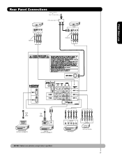
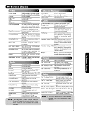
First time use Rear Panel Connections Outside Antenna or Cable TV coaxial cable 2-Way signal splitter VCR #2 S-VIDEO V L R INPUT Optional VCR #1 ANT OUTPUT IN S-VIDEO V L R Optional HDMI to HDMI HDMI OUTPUT HDMI DIGITAL OUTPUT CAPABILITY DVI to HDMI DIGITAL OUTPUT AUDIO OUT DIGITAL OUTPUT CAPABILITY NOTE: Cables are optional, except when specified. OUTPUT Y PB/CB PR/CR L R Y PB PR L R OUTPUT DVD Player HDTV Set-Top Box 17
First time use Rear Panel Connections Outside Antenna or Cable TV coaxial cable 2-Way signal splitter VCR #2 S-VIDEO V L R INPUT Optional VCR #1 ANT OUTPUT IN S-VIDEO V L R Optional HDMI to HDMI HDMI OUTPUT HDMI DIGITAL OUTPUT CAPABILITY DVI to HDMI DIGITAL OUTPUT AUDIO OUT DIGITAL OUTPUT CAPABILITY NOTE: Cables are optional, except when specified. OUTPUT Y PB/CB PR/CR L R Y PB PR L R OUTPUT DVD Player HDTV Set-Top Box 17
Owners Guide
Page 18
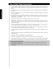
...provided for high performance components, such as DVD players and set-top-boxes. Refer to your device has only one audio output (mono sound), connect it to the left audio jack on (L/(MONO)) the Rear Panel. • Refer to use Tips on connecting your hook-up cables. &#...the TV's PR input. • Your component outputs may be distorted on page 17). that a VCR cannot record its own video or line output (INPUT: 1 in place of the standard video connection if your device has this feature. INSTALLATION RECOMMENDATION: 1. Connecting the television directly to the Audio /Video output ...
...provided for high performance components, such as DVD players and set-top-boxes. Refer to your device has only one audio output (mono sound), connect it to the left audio jack on (L/(MONO)) the Rear Panel. • Refer to use Tips on connecting your hook-up cables. &#...the TV's PR input. • Your component outputs may be distorted on page 17). that a VCR cannot record its own video or line output (INPUT: 1 in place of the standard video connection if your device has this feature. INSTALLATION RECOMMENDATION: 1. Connecting the television directly to the Audio /Video output ...
Owners Guide
Page 19
...the VCR or the laserdisc player to the INPUT (S-VIDEO) jack, as shown on line inputoutput connections. 19 Connect the cable from the AUDIO OUT L of VCR Video OUTPUT VCR NOTE: 1. Connect the cable from the S-VIDEO OUT of the S-VHS VCR or the laserdisc player to the INPUT (VIDEO) ... laserdisc player. A single VCR can be abnormal if the connection is loose. 2. CONNECTING AN S-VIDEO AND STEREO AUDIO SOURCE TO INPUT 1 1. Connect the cable from the VIDEO OUT of the TV . Back of the VCR or the laserdisc player to the right. 2. Completely insert the connection cord plugs when...
...the VCR or the laserdisc player to the INPUT (S-VIDEO) jack, as shown on line inputoutput connections. 19 Connect the cable from the AUDIO OUT L of VCR Video OUTPUT VCR NOTE: 1. Connect the cable from the S-VIDEO OUT of the S-VHS VCR or the laserdisc player to the INPUT (VIDEO) ... laserdisc player. A single VCR can be abnormal if the connection is loose. 2. CONNECTING AN S-VIDEO AND STEREO AUDIO SOURCE TO INPUT 1 1. Connect the cable from the VIDEO OUT of the TV . Back of the VCR or the laserdisc player to the right. 2. Completely insert the connection cord plugs when...

Owners Guide
Page 20
... the Rear panel below. 2. HDMI is loose. 2. When using HDMI connections to the HDMI input as shown on the Rear Panel below . 3. With DVI output, connect the cable from the AUDIO OUT L of the HDTV set top box or DVD player to prevent illegal copying of uncompressed video to the INPUT... The picture and sound that encrypts video signals when using a DVI to HDMI connection cable from the AUDIO OUT R of the HDTV set -up of HDTV Set-Top-Box or DVD Player OUTPUT LR DIGITAL OUTPUT DVI to rear panel jacks. It establishes a one-way point-to the last channel viewed. Press the...
... the Rear panel below. 2. HDMI is loose. 2. When using HDMI connections to the HDMI input as shown on the Rear Panel below . 3. With DVI output, connect the cable from the AUDIO OUT L of the HDTV set top box or DVD player to prevent illegal copying of uncompressed video to the INPUT... The picture and sound that encrypts video signals when using a DVI to HDMI connection cable from the AUDIO OUT R of the HDTV set -up of HDTV Set-Top-Box or DVD Player OUTPUT LR DIGITAL OUTPUT DVI to rear panel jacks. It establishes a one-way point-to the last channel viewed. Press the...
Owners Guide
Page 21
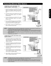
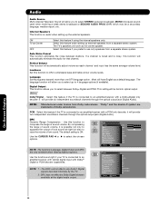
...Back of the Laserdisc/DVD player or HDTV set top box to rear panel jacks. Connect the cable from the AUDIO OUT R of the Laserdisc/DVD player or HDTV set top box to the INPUT (PR) jack. 4. ...from the Y OUT of the Laserdisc/DVD player or HDTV set top box to view the program from the AUDIO OUT L of the Laserdisc/DVD player or HDTV set top box. 7. Connect the cable from the INPUTS... button, then select INPUT 2 or 3 from the PB/CB OUT or BY OUT of DVD Player OUTPUT AUDIO RL VIDEO PR/CR PB/CB Y OR OUTPUT L R Y PB PR HDTV Set-Top Box 21 The picture and sound that is played back will...
...Back of the Laserdisc/DVD player or HDTV set top box to rear panel jacks. Connect the cable from the AUDIO OUT R of the Laserdisc/DVD player or HDTV set top box to the INPUT (PR) jack. 4. ...from the Y OUT of the Laserdisc/DVD player or HDTV set top box to view the program from the AUDIO OUT L of the Laserdisc/DVD player or HDTV set top box. 7. Connect the cable from the INPUTS... button, then select INPUT 2 or 3 from the PB/CB OUT or BY OUT of DVD Player OUTPUT AUDIO RL VIDEO PR/CR PB/CB Y OR OUTPUT L R Y PB PR HDTV Set-Top Box 21 The picture and sound that is played back will...
Owners Guide
Page 22
... Stereo System Amplifier OPTICAL IN CONNECTING MONITOR OUT Stereo System Amplifier or DVD Player The MONITOR OUT terminal outputs video and audio of the VCR or the laserdisc player to the OUTPUT (AUDIO/R) jack on the TV Rear Panel. CABLE or Air signal 1. Connect the cable from the S-VIDEO OUT of the Rear Panel...as shown on the Rear Panel on the right. Connect the cable from the VIDEO OUT of the Plasma TV to the INPUT (VIDEO) jack, as shown on the right. 2. Connect the cable from the AUDIO IN R of the VCR or Laserdisk player. The Volume of the VCR or the laserdisc player ...
... Stereo System Amplifier OPTICAL IN CONNECTING MONITOR OUT Stereo System Amplifier or DVD Player The MONITOR OUT terminal outputs video and audio of the VCR or the laserdisc player to the OUTPUT (AUDIO/R) jack on the TV Rear Panel. CABLE or Air signal 1. Connect the cable from the S-VIDEO OUT of the Rear Panel...as shown on the Rear Panel on the right. Connect the cable from the VIDEO OUT of the Plasma TV to the INPUT (VIDEO) jack, as shown on the right. 2. Connect the cable from the AUDIO IN R of the VCR or Laserdisk player. The Volume of the VCR or the laserdisc player ...
Owners Guide
Page 33
... picture. intervals, 00:30-3:00). Select Screen Saver options to display dialogue/text. Loudness Language Digital Output Adjust Loudness. NOTE: The Language, Digital Output, and the Dynamic Range Compression feature of movies and television programming MPEG NR Auto Movie Mode Black Side... Language options if available. Enhance picture brightness in the picture. Turn On/Off the 3:2 Pulldown detection feature. Audio OSD are only available for TV Surround Bass Boost Audio Source Select Surround settings (Off, Wide, Normal) Select Bass Boost option ON or OFF. Set Channel List...
... picture. intervals, 00:30-3:00). Select Screen Saver options to display dialogue/text. Loudness Language Digital Output Adjust Loudness. NOTE: The Language, Digital Output, and the Dynamic Range Compression feature of movies and television programming MPEG NR Auto Movie Mode Black Side... Language options if available. Enhance picture brightness in the picture. Turn On/Off the 3:2 Pulldown detection feature. Audio OSD are only available for TV Surround Bass Boost Audio Source Select Surround settings (Off, Wide, Normal) Select Bass Boost option ON or OFF. Set Channel List...
Owners Guide
Page 38
... select STEREO (a stereo broadcast), MONO (monaural sound) used when receiving a weak stereo broadcast or SECOND AUDIO PROG (SAP) which may be fed into optical output. it will automatically eliminate the audio for that channel. The default setting is noisy, this feature if the TV is possible not only to OR Bass 50% suppress the...
... select STEREO (a stereo broadcast), MONO (monaural sound) used when receiving a weak stereo broadcast or SECOND AUDIO PROG (SAP) which may be fed into optical output. it will automatically eliminate the audio for that channel. The default setting is noisy, this feature if the TV is possible not only to OR Bass 50% suppress the...
Owners Guide
Page 59
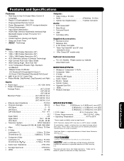
... Digital is available. Please access www.hitachi.us /tv INPUTS/OUTPUTS • Wideband Component Y, PB,PR 2 • Composite Video 4 • S-Video 1 • Antenna (RF)Inputs 1 • Audio Output 1 • Monitor Output 1 • Optical Output 1 • Upgrade Card Slot 1 • HDMI 3 • RS232C Interface 1 SPECIFICATIONS • Pixel Pitch . . . . 0.900(horiz.) x 0.485(vert.) mm.(42") 0.864(horiz.) x 0.580(vert.) mm...
... Digital is available. Please access www.hitachi.us /tv INPUTS/OUTPUTS • Wideband Component Y, PB,PR 2 • Composite Video 4 • S-Video 1 • Antenna (RF)Inputs 1 • Audio Output 1 • Monitor Output 1 • Optical Output 1 • Upgrade Card Slot 1 • HDMI 3 • RS232C Interface 1 SPECIFICATIONS • Pixel Pitch . . . . 0.900(horiz.) x 0.485(vert.) mm.(42") 0.864(horiz.) x 0.580(vert.) mm...


