Instruction Manual
Page 6
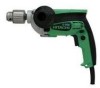
..." wire will make exposed metal parts of the tool "live" and shock the operator. 2. For D10VG, D13VF and D13VG ALWAYS attach the side handle and securely grip the Drill. 6. Handle tool correctly. Do not drop or throw the tool. Keep all guards in the Instruction Manual. 10. ... an operation where the cutting tool may contact hidden wiring or its operation or unauthorized personnel. 11. For D10VF ALWAYS securely grip the Drill. NEVER operate this tool without all screws, bolts, and plates tightly mounted. Check their condition periodically. 12. English SPECIFIC SAFETY RULES ...
..." wire will make exposed metal parts of the tool "live" and shock the operator. 2. For D10VG, D13VF and D13VG ALWAYS attach the side handle and securely grip the Drill. 6. Handle tool correctly. Do not drop or throw the tool. Keep all guards in the Instruction Manual. 10. ... an operation where the cutting tool may contact hidden wiring or its operation or unauthorized personnel. 11. For D10VF ALWAYS securely grip the Drill. NEVER operate this tool without all screws, bolts, and plates tightly mounted. Check their condition periodically. 12. English SPECIFIC SAFETY RULES ...
Instruction Manual
Page 9
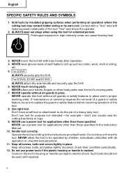
Some illustrations in this manual. NEVER operate, or attempt any maintenance on your own power tool NAME OF PARTS Gear Cover Housing Nameplate Drill Chuck Side Handle Switch Trigger Handle Cover Push Button Stopper Fig. 1 9 English FUNCTIONAL DESCRIPTION NOTE: The information contained in this Instruction Manual is designed to assist you have first read and understood all safety instructions contained in this Instruction Manual may show details or attachments that differ from those on the tool unless you in the safe operation and maintenance of the power tool.
Some illustrations in this manual. NEVER operate, or attempt any maintenance on your own power tool NAME OF PARTS Gear Cover Housing Nameplate Drill Chuck Side Handle Switch Trigger Handle Cover Push Button Stopper Fig. 1 9 English FUNCTIONAL DESCRIPTION NOTE: The information contained in this Instruction Manual is designed to assist you have first read and understood all safety instructions contained in this Instruction Manual may show details or attachments that differ from those on the tool unless you in the safe operation and maintenance of the power tool.
Instruction Manual
Page 10
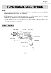
...2-1/4"(57mm) 1-3/4"(44mm) 2-9/16"(65mm) 2-1/8"(54mm) Hole Saw 4-1/2"(114mm) 2-1/2"(64mm) 4-1/2"(114mm) 4"(102mm) 10 English SPECIFICATIONS Model D10VF D10VG D13VF D13VG Motor Single Phase, Series Commutator Motor Power Source Single Phase 120V AC 60 Hz Current 9.0A No-Load Speed 0-3000/min. 0-1200/min.... 0-850/min. 0-600/min. Drill Chuck Capacity 3/8" (10mm) 1/2" (13mm) Electric Brake No No Yes Yes Capacity Steel Twist Bit 3/8"(10mm) 3/8"(10mm) 1/2"(13mm) 1/2"(13mm) ...
...2-1/4"(57mm) 1-3/4"(44mm) 2-9/16"(65mm) 2-1/8"(54mm) Hole Saw 4-1/2"(114mm) 2-1/2"(64mm) 4-1/2"(114mm) 4"(102mm) 10 English SPECIFICATIONS Model D10VF D10VG D13VF D13VG Motor Single Phase, Series Commutator Motor Power Source Single Phase 120V AC 60 Hz Current 9.0A No-Load Speed 0-3000/min. 0-1200/min.... 0-850/min. 0-600/min. Drill Chuck Capacity 3/8" (10mm) 1/2" (13mm) Electric Brake No No Yes Yes Capacity Steel Twist Bit 3/8"(10mm) 3/8"(10mm) 1/2"(13mm) 1/2"(13mm) ...
Instruction Manual
Page 11
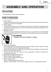
...power source requirements specified on the product nameplate. 2. PRIOR TO OPERATION 1. The extension cord should be replaced or repaired. 4. However, when drilling 1/4" (6.5 mm) or smaller holes, use an extension cord of sufficient thickness and rated capacity. WARNING: Damaged cord must be utilized conforms... to make appropriate repairs. If such a fautly receptacle is far away from the power source, use a metalworking drill bit. 11 Check the receptacle If the receptacle only loosely accepts the plug, the receptacle must be kept as short as practicable...
...power source requirements specified on the product nameplate. 2. PRIOR TO OPERATION 1. The extension cord should be replaced or repaired. 4. However, when drilling 1/4" (6.5 mm) or smaller holes, use an extension cord of sufficient thickness and rated capacity. WARNING: Damaged cord must be utilized conforms... to make appropriate repairs. If such a fautly receptacle is far away from the power source, use a metalworking drill bit. 11 Check the receptacle If the receptacle only loosely accepts the plug, the receptacle must be kept as short as practicable...
Instruction Manual
Page 12
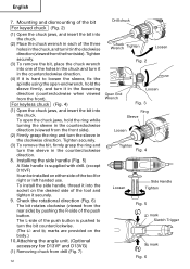
... chuck and turn the sleeve in the counterclockwise direction (viewed from the rear side) by pushing the R-side of the tool for D13VF and D13VG) (1) Removing chuck from the front side). Check the rotational direction (Fig. 6) The bit rotates clockwise (viewed from the front side). (2)...jaws, and insert the bit into one of the three holes in the chuck, and turn the sleeve in the clockwise direction (viewed from drill (Fig. 7) 12 Drill chuck Chuck Wrench Tighten Loosen Fig. 2 Open End Wrench Loosen Fig. 3 Ring Sleeve Loosen Tighten Fig. 4 Loosen Side Handle Tighten Fig....
... chuck and turn the sleeve in the counterclockwise direction (viewed from the rear side) by pushing the R-side of the tool for D13VF and D13VG) (1) Removing chuck from the front side). Check the rotational direction (Fig. 6) The bit rotates clockwise (viewed from the front side). (2)...jaws, and insert the bit into one of the three holes in the chuck, and turn the sleeve in the clockwise direction (viewed from drill (Fig. 7) 12 Drill chuck Chuck Wrench Tighten Loosen Fig. 2 Open End Wrench Loosen Fig. 3 Ring Sleeve Loosen Tighten Fig. 4 Loosen Side Handle Tighten Fig....
Instruction Manual
Page 13
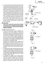
... ⅜ To remove the chuck from the spindle which can be subjected by striking the wrench, don't strike the wrench forcibly and send the drill to a HITACHI AUTHORIZED SERVICE CENTER. (2) Attaching the angle unit. ⅜ After removing the chuck, engage the coupling to the... drill spindle. Turn the chuck until the wrench is decreased to about 70% and the drilling torque increased to about a 30° angle to the bench top and strike the wrench sharply with a ...
... ⅜ To remove the chuck from the spindle which can be subjected by striking the wrench, don't strike the wrench forcibly and send the drill to a HITACHI AUTHORIZED SERVICE CENTER. (2) Attaching the angle unit. ⅜ After removing the chuck, engage the coupling to the... drill spindle. Turn the chuck until the wrench is decreased to about 70% and the drilling torque increased to about a 30° angle to the bench top and strike the wrench sharply with a ...
Instruction Manual
Page 14
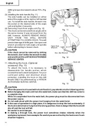
...(3) Installing the side handle (Fig. 11) The side handle can be installed on this drill should ONLY be removed by striking the wrench, don't strike the wrench forcibly and send the drill to a HITACHI AUTHORIZED SERVICE CENTER. 11. Use open end wrench provided to hold angle unit spindle before ... CAUTION: When the power tool is used with the power tool hanging from example. Be careful you are not hurt by a HITACHI AUTHORIZED SERVICE CENTER. English drilling torque decreased to about with a hook fixed to it, pay attention to the following points: ⅷ Before hanging the main unit...
...(3) Installing the side handle (Fig. 11) The side handle can be installed on this drill should ONLY be removed by striking the wrench, don't strike the wrench forcibly and send the drill to a HITACHI AUTHORIZED SERVICE CENTER. 11. Use open end wrench provided to hold angle unit spindle before ... CAUTION: When the power tool is used with the power tool hanging from example. Be careful you are not hurt by a HITACHI AUTHORIZED SERVICE CENTER. English drilling torque decreased to about with a hook fixed to it, pay attention to the following points: ⅷ Before hanging the main unit...
Instruction Manual
Page 15
Be careful not to a HITACHI AUTHORIZED SERVICE CENTRE. 3. Speed is low when the trigger switch is pulled slightly and increases as you drill. ⅜ Always apply pressure in an attempt to the material being drilled. 15 This can be applied for continuous running. To maintain firm control, establish a good ... ease the bit through the last part of the drill can damage the drill. ⅜ The larger the drill bit diameter, the larger the reactive force on your arm. When the trigger is pulled. Electric brake (D13VF and D13VG) When releasing the trigger of this reactive force. Do ...
Be careful not to a HITACHI AUTHORIZED SERVICE CENTRE. 3. Speed is low when the trigger switch is pulled slightly and increases as you drill. ⅜ Always apply pressure in an attempt to the material being drilled. 15 This can be applied for continuous running. To maintain firm control, establish a good ... ease the bit through the last part of the drill can damage the drill. ⅜ The larger the drill bit diameter, the larger the reactive force on your arm. When the trigger is pulled. Electric brake (D13VF and D13VG) When releasing the trigger of this reactive force. Do ...
Instruction Manual
Page 16
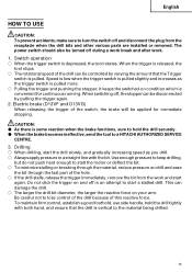
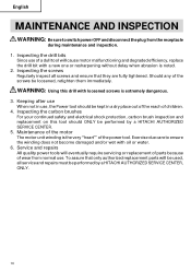
...to switch power OFF and disconnect the plug from normal use , the Power tool should ONLY be performed by a HITACHI AUTHORIZED SERVICE CENTER. 5. Inspecting the drill bits Since use of wear from the receptacle during maintenance and inspection. 1. Inspecting the carbon brushes For your continued ...or resharpening without delay when abrasion is extremely dangerous. 3. Inspecting the screws Regularly inspect all service and repairs must be performed by a HITACHI AUTHORIZED SERVICE CENTER, ONLY. 16 Keeping after use When not in a dry place out of the reach of the power tool. Should...
...to switch power OFF and disconnect the plug from normal use , the Power tool should ONLY be performed by a HITACHI AUTHORIZED SERVICE CENTER. 5. Inspecting the drill bits Since use of wear from the receptacle during maintenance and inspection. 1. Inspecting the carbon brushes For your continued ...or resharpening without delay when abrasion is extremely dangerous. 3. Inspecting the screws Regularly inspect all service and repairs must be performed by a HITACHI AUTHORIZED SERVICE CENTER, ONLY. 16 Keeping after use When not in a dry place out of the reach of the power tool. Should...

Parts List
Page 3
...PLATE 1 HANDLE (B) 1 TAPPING SCREW (W/FLANGE) D4X35 2 TAPPING SCREW (W/FLANGE) D4X20 (BLACK) 1 GRIP COVER 1 SCREW (PLASTIC TIE) D4X25 2 HITACHI LABEL 1 HANDLE (A) 1 BRUSH HOLDER 2 INTERNAL WIRE (BLUE) 86L 1 FOR USA,CAN CHOKE COIL (BLUE) 220V-240V 1 FOR AUS,NZL,EUROPE...* ALTERNATIVE PARTS D 13VG --- 3 --- USED REMARKS SPECIAL SCREW (LEFT HAND) M6X23 1 CHUCK WRENCH 13VLR-J 1 VINYL BAND 1 DRILL CHUCK 13VLR-J 1 INCLUD.2 DRILL CHUCK 13VLRD-N (W/O CHUCK WRENCH) 1 SPINDLE (A) 1 RETAINING RING FOR D32 HOLE 1 BALL BEARING 6002VVCMPS2L 1 RETAINING RING FOR D15 SHAFT...
...PLATE 1 HANDLE (B) 1 TAPPING SCREW (W/FLANGE) D4X35 2 TAPPING SCREW (W/FLANGE) D4X20 (BLACK) 1 GRIP COVER 1 SCREW (PLASTIC TIE) D4X25 2 HITACHI LABEL 1 HANDLE (A) 1 BRUSH HOLDER 2 INTERNAL WIRE (BLUE) 86L 1 FOR USA,CAN CHOKE COIL (BLUE) 220V-240V 1 FOR AUS,NZL,EUROPE...* ALTERNATIVE PARTS D 13VG --- 3 --- USED REMARKS SPECIAL SCREW (LEFT HAND) M6X23 1 CHUCK WRENCH 13VLR-J 1 VINYL BAND 1 DRILL CHUCK 13VLR-J 1 INCLUD.2 DRILL CHUCK 13VLRD-N (W/O CHUCK WRENCH) 1 SPINDLE (A) 1 RETAINING RING FOR D32 HOLE 1 BALL BEARING 6002VVCMPS2L 1 RETAINING RING FOR D15 SHAFT...


