Instruction Manual
Page 6
... their condition periodically. 12. Cracks in place. Prevent potential injuries to roll up such as cotton, wool, cloth or string, etc. 5. ALWAYS securely grip the Drill. 6. Use right tool. don't use a power tool for example- NEVER use power tools if the plastic housing or handle is cracked. Handle tool correctly. NEVER...
... their condition periodically. 12. Cracks in place. Prevent potential injuries to roll up such as cotton, wool, cloth or string, etc. 5. ALWAYS securely grip the Drill. 6. Use right tool. don't use a power tool for example- NEVER use power tools if the plastic housing or handle is cracked. Handle tool correctly. NEVER...

Instruction Manual
Page 9
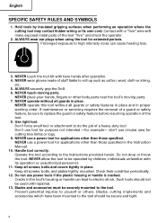
... Speed Control Dial Switch Trigger Handle Cover Push Button Stopper SPECIFICATIONS Motor Power Source Current No-Load Speed Drill Chuck Capacity Capacity Steel Twist Bit Wood Flat Spade Bit Auger Bit Weight (without cord) Fig. 1 Single Phase, Series Commutator Motor Single Phase 120V AC ...
... Speed Control Dial Switch Trigger Handle Cover Push Button Stopper SPECIFICATIONS Motor Power Source Current No-Load Speed Drill Chuck Capacity Capacity Steel Twist Bit Wood Flat Spade Bit Auger Bit Weight (without cord) Fig. 1 Single Phase, Series Commutator Motor Single Phase 120V AC ...
Instruction Manual
Page 10
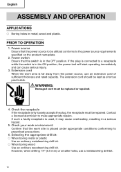
... immediately and can cause serious injury. 3. English ASSEMBLY AND OPERATION APPLICATIONS ⅜ Boring holes in a serious hazard. 5. However, when drilling 1/4" (6.5 mm) or smaller holes, use an extension cord of sufficient thickness and rated capacity. Power source Ensure that the switch is ...must be utilized conforms to make appropriate repairs. Selecting the appropriate drill bit: ⅜ When boring metal or plastic Use an ordinary metalworking drill bit. ⅜ When boring wood Use an ordinary woodworking drill bit. WARNING: Damaged cord must be kept as short as ...
... immediately and can cause serious injury. 3. English ASSEMBLY AND OPERATION APPLICATIONS ⅜ Boring holes in a serious hazard. 5. However, when drilling 1/4" (6.5 mm) or smaller holes, use an extension cord of sufficient thickness and rated capacity. Power source Ensure that the switch is ...must be utilized conforms to make appropriate repairs. Selecting the appropriate drill bit: ⅜ When boring metal or plastic Use an ordinary metalworking drill bit. ⅜ When boring wood Use an ordinary woodworking drill bit. WARNING: Damaged cord must be kept as short as ...
Instruction Manual
Page 11
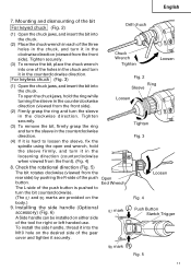
... Fig. 2 Ring Sleeve Loosen Tighten Fig. 3 8. Loosen Fig. 4 Push Button Siwtch Trigger R mark Fig. 5 11 Mounting and dismounting of the bit For keyed chuck (Fig. 2) Drill chuch (1) Open the chuck jaws, and insert the bit into one of the tool for right or left handed use. End Wrench The L-side of...
... Fig. 2 Ring Sleeve Loosen Tighten Fig. 3 8. Loosen Fig. 4 Push Button Siwtch Trigger R mark Fig. 5 11 Mounting and dismounting of the bit For keyed chuck (Fig. 2) Drill chuch (1) Open the chuck jaws, and insert the bit into one of the tool for right or left handed use. End Wrench The L-side of...
Instruction Manual
Page 12
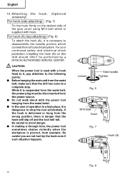
For hook (A) (top-attaching) (Fig. 8) To attach the hook (A), it is danger that the drill has come to a complete stop. Loosen Side handle Tighten Fig. 6 M10 Bolt Hook Fig. 7 Hook (A) Fig. 8 12 If the hook is deformed or hung from ... performed by the hook even if such situation happens. Be careful you are not hurt by a HITACHI AUTHORIZED SERVICE CENTER. Attaching the hook. (Optional accessory) For hook (side-attaching) (Fig. 7) Fix the hook firmly on this drill should ONLY be disconnected from the power source. ⅷ Do not walk about with the...
For hook (A) (top-attaching) (Fig. 8) To attach the hook (A), it is danger that the drill has come to a complete stop. Loosen Side handle Tighten Fig. 6 M10 Bolt Hook Fig. 7 Hook (A) Fig. 8 12 If the hook is deformed or hung from ... performed by the hook even if such situation happens. Be careful you are not hurt by a HITACHI AUTHORIZED SERVICE CENTER. Attaching the hook. (Optional accessory) For hook (side-attaching) (Fig. 7) Fix the hook firmly on this drill should ONLY be disconnected from the power source. ⅷ Do not walk about with the...

Instruction Manual
Page 13
...speed control dial. Speed is low when the trigger switch is pulled slightly and increases as you drill. ⅜ Always apply pressure in an attempt to start a stalled drill. Drilling ⅜ When drilling, start again. The power switch should also be turned off during a work break and after...continuous running. This can be Stopper controlled by pulling the trigger again. 2. When switching off, the stopper can damage the drill. ⅜ The larger the drill bit diameter, the larger the reactive force on condition which is depressed, the tool rotates. Be careful not to lose ...
...speed control dial. Speed is low when the trigger switch is pulled slightly and increases as you drill. ⅜ Always apply pressure in an attempt to start a stalled drill. Drilling ⅜ When drilling, start again. The power switch should also be turned off during a work break and after...continuous running. This can be Stopper controlled by pulling the trigger again. 2. When switching off, the stopper can damage the drill. ⅜ The larger the drill bit diameter, the larger the reactive force on condition which is depressed, the tool rotates. Be careful not to lose ...
Instruction Manual
Page 14
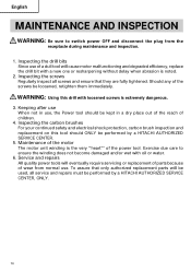
... a dull tool will be used, all screws and ensure that only authorized replacement parts will cause motor malfunctioning and degraded efficiency, replace the drill bit with a new one or resharpening without delay when abrasion is noted. 2. Should any of children. 4. Inspecting the screws Regularly inspect ... immediately. Keeping after use When not in a dry place out of the reach of the screws be performed by a HITACHI AUTHORIZED SERVICE CENTER. 5. Inspecting the carbon brushes For your continued safety and electrical shock protection, carbon brush inspection and replacement on this...
... a dull tool will be used, all screws and ensure that only authorized replacement parts will cause motor malfunctioning and degraded efficiency, replace the drill bit with a new one or resharpening without delay when abrasion is noted. 2. Should any of children. 4. Inspecting the screws Regularly inspect ... immediately. Keeping after use When not in a dry place out of the reach of the screws be performed by a HITACHI AUTHORIZED SERVICE CENTER. 5. Inspecting the carbon brushes For your continued safety and electrical shock protection, carbon brush inspection and replacement on this...
Parts List
Page 1
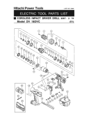
G861 ELECTRIC TOOL PARTS LIST CORDLESS IMPACT DRIVER DRILL 2007 • 3 • 19 Model DV 18DVC (E1) 1 2 8 9 10 11 12 13 14 3 4 5 6 7 27 28 29 30 29 31 15 16 17 18 19 18 20 32 21 22 33 23 24 34 25 26 501 502 503 37 38 40 39 42 41 46 43 44 45 35 36 51 47 48 49 50 49 48 47 Hitachi Power Tools LIST NO.
G861 ELECTRIC TOOL PARTS LIST CORDLESS IMPACT DRIVER DRILL 2007 • 3 • 19 Model DV 18DVC (E1) 1 2 8 9 10 11 12 13 14 3 4 5 6 7 27 28 29 30 29 31 15 16 17 18 19 18 20 32 21 22 33 23 24 34 25 26 501 502 503 37 38 40 39 42 41 46 43 44 45 35 36 51 47 48 49 50 49 48 47 Hitachi Power Tools LIST NO.

Parts List
Page 2
DESCRIPTION NO. SCREW (A) (LEFT HAND) M6X25 1 2 322-625 DRILL CHUCK 13VLRJ-N (W/O CHUCK WRENCH) 1 3 327-131 GEAR BOX ASS'Y 1 INCLUD. 4-33 4 327-149 CLUTCH DIAL 1 5 327-146 CLICK SPRING 1 6 327-142 O-RING 1 7 327-137 SPINDLE 1 8 ... 1 35 NAME PLATE 1 36 313-687 TAPPING SCREW (W/FLANGE) D3X16 (BLACK) 8 37 317-333 MACHINE SCREW (W/SP. WASHER) M4X6 2 38 323-229 FERRITE CORE 1 39 HITACHI LABEL 1 40 327-152 HOUSING (A).(B) SET 1 41 328-057 INTERNAL WIRE (BLACK) 150L 1 42 328-056 INTERNAL WIRE (RED) 150L 1 43 327-151 PUSHING BUTTON...
DESCRIPTION NO. SCREW (A) (LEFT HAND) M6X25 1 2 322-625 DRILL CHUCK 13VLRJ-N (W/O CHUCK WRENCH) 1 3 327-131 GEAR BOX ASS'Y 1 INCLUD. 4-33 4 327-149 CLUTCH DIAL 1 5 327-146 CLICK SPRING 1 6 327-142 O-RING 1 7 327-137 SPINDLE 1 8 ... 1 35 NAME PLATE 1 36 313-687 TAPPING SCREW (W/FLANGE) D3X16 (BLACK) 8 37 317-333 MACHINE SCREW (W/SP. WASHER) M4X6 2 38 323-229 FERRITE CORE 1 39 HITACHI LABEL 1 40 327-152 HOUSING (A).(B) SET 1 41 328-057 INTERNAL WIRE (BLACK) 150L 1 42 328-056 INTERNAL WIRE (RED) 150L 1 43 327-151 PUSHING BUTTON...


